


Belangrijke aspecten van het ontwerp van hoogovens en bijbehorende hulpapparatuur
Belangrijke aspecten van het ontwerp van de hoogoven en bijbehorende hulpapparatuur
Het ontwerp van de eigenlijke hoogoven (BF) en de bijbehorende en aanvullende uitrustingen (Fig 1) onmiddellijk stroomopwaarts en stroomafwaarts van de oven is belangrijk voor de efficiënte werking van de BF. Naast de eigenlijke oven, omvatten de onmiddellijke bijbehorende apparatuur (i) het voorraadhuis, (ii) de laadapparatuur, (iii) de oventop, (iv) het koelsysteem en (v) de apparatuur voor het giethuis.
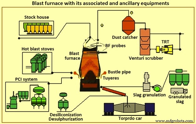
Fig 1 Hoogoven met bijbehorende en aanvullende apparatuur
BF ijzerproductie bestaat uit een systeem dat bestaat uit verschillende componenten die in harmonie functioneren. Een juiste toepassing en werking van deze componenten is noodzakelijk om het ijzerproductieproces te ondersteunen. De selectie van specifieke componenten is afhankelijk van factoren als bestaande omstandigheden, fysieke beperkingen, productievereisten, kosten, planning, betrouwbaarheid en onderhoudbaarheid. De onderlinge afhankelijkheid van componenten is net zo belangrijk voor de succesvolle werking van het systeem als hun individuele mogelijkheden. Er zijn belangrijke eisen en 'normale' praktijken voor elk gebied of onderdeel. Er zijn ook enkele alternatieve technologieën die in de handel verkrijgbaar zijn en die inherente voor- en nadelen hebben.
BF zet ijzerhoudende ertsbelasting om in vloeibaar ijzer (ruwijzer). Bij de BF horen cokesovens, batterijen die steenkool omzetten in cokes, en sinter- en pelletfabrieken, die ijzererts voor de BF bereiden. Het BF zet deze bereide grondstoffen om in een product van hogere waarde. Heet metaal van enkele van de BFs-activiteiten wordt in gieterijen gebruikt voor de productie van ijzergietwerk. Andere bewerkingen produceren een heet metaal met een lager siliciumgehalte dat wordt omgezet in staal in een staalsmelterij. Een deel van het ruwijzer wordt in de varkensgietmachines omgezet in ruwijzer. De bijproducten van BF zijn slakken, BF-topgas, rookgas en filterkoek. Deze bijproducten kunnen zowel een positieve als een negatieve economische impact hebben, afhankelijk van de lokale gebruiksmogelijkheden.
Enkele van de verschillende aspecten die van invloed zijn op elke overweging voor het ontwerp of herontwerp van BF zijn (i) winst, (ii) gezondheid en veiligheid van werknemers, (iii) milieubescherming, (iv) wettelijke voorschriften, (v) behoeften van de markt- en downstreamverwerking, (vi) beschikbare personele, constructie- en onderhoudsmiddelen, (vii) veranderende technologieën en veroudering van apparatuur, (viii) beschikbare grondstoffen, nutsvoorzieningen en andere materialen, en (ix) enzovoort. Elke ernstige beperking in een van deze aspecten kan de levensvatbaarheid van de BF-eenheid (of zelfs een staalfabriek) in gevaar brengen of de bouw van een nieuwe BF uitsluiten of noodzakelijk maken.
BF's worden normaal gegroepeerd op grootte. Mini BF's produceren minder dan 1.500 ton ruwijzer per dag (tHM/dag), kleine BF's produceren in het bereik van ongeveer 2.500 tHM/dag tot 5.000 tHM/dag, middelgrote BF's produceren in het bereik van ongeveer 6.000 tHM/dag tot 8.000 tHM/dag, en grote BF's produceren ongeveer 9.000 tHM/dag tot 12.000 tHM per dag. In een geïntegreerde staalfabriek zijn een aantal en maten BF's nodig om het ruwijzer te leveren dat nodig is voor de productie van staal. Geïntegreerde staalfabrieken met een aantal BF's worden minder getroffen wanneer een BF relining-reparaties ondergaat of wanneer er problemen zijn met de ovenbesturing. Kleine BF's hebben kortere relining-reparaties dan grote BF's en worden als gemakkelijker te bedienen beschouwd. De kosten van ruwijzer van kleine BF's zijn echter hoger. De geïntegreerde staalfabriek is nodig om het minimum aantal kosteneffectieve ovens te laten werken. In sommige gevallen worden upgrades uitgevoerd om het aantal ovens dat in bedrijf is te verminderen.
BF's worden periodiek opnieuw gelijnd na het einde van de campagne (tijd tussen reparatie van relining). In het verleden betrof dit de vervanging van de interne gemetselde bekleding van de hoofdoven. De laatste tijd worden uitgebreide revisie, vervanging en preventief onderhoud van componenten tegelijkertijd uitgevoerd. Met deze praktijk verliest de efficiëntere staalfabriek met minder grote BF's een hoger percentage van zijn productie tijdens de BF-reliningreparatie dan de fabriek met meer kleine ovens. Om zowel de lage bedrijfskosten als de minimale interferentie tijdens de BF-relines te hebben, heeft de industrie gewerkt om de campagne van de BF's te maximaliseren en de duur van de relining-reparatie te verkorten. De huidige duidelijke trend in de geïntegreerde staalfabrieken is om minder grote ovens te gebruiken en technieken en ontwerpen te gebruiken die de BFs-campagne voor onbepaalde tijd verlengen.
Tegelijkertijd is het verminderen van productvariabiliteit belangrijker geworden en daarom wordt geïnvesteerd in automatisering die de monitoring en beheersing van het proces verbetert. BF-operators, onderhoudspersoneel, ontwerpers en onderzoekspersoneel hebben moderne technologie en analytische methoden toegepast op het BF-proces om het proces beter te bewaken en te beheersen. Hierdoor is de standaarddeviatie van de ruwijzerkwaliteit verminderd. Verbeterde systemen voor gegevensverzameling bieden ook meer informatie voor leveranciers en fabrikanten. Dit heeft de materiaalkeuze en het ontwerp van de BF's en bijbehorende apparatuur verbeterd. De lengte van de campagne is toegenomen tot ongeveer 20 jaar eerder, van 5 jaar tot 10 jaar.
BF-ijzerproductie is een technologie van meer dan 430 jaar oud. Toch is het gebruik van BF-ruwijzer nog steeds de meest gebruikte methode in de geïntegreerde staalfabrieken voor de productie van staal. Hedendaagse geïntegreerde staalfabriekprocessen vertrouwen op de BF om op schema voorspelbare hoeveelheden ruwijzer van constante kwaliteit te leveren. Variatie in een van de aspecten van de levering van ruwijzer heeft een ernstige impact op de rest van de staalproductieprocessen. Daarom blijft de BF een belangrijk proces in de moderne geïntegreerde staalfabrieken.
Er wordt wel eens beweerd dat de procestechnologie van BF aan het einde van zijn levensduur is. Dit is niet zo. De studie van bedrijfsgegevens van 23 jaar (1970 tot 1993) van een typisch paar middelgrote BF's heeft aangetoond dat er een gemiddelde productiviteitstoename van 3% per jaar is (Fig. 2a). Tegelijkertijd was de gemiddelde verlaging van het brandstofverbruik 1% per jaar (Fig. 2b). Ook is de productieve tijd tussen de BF-relining (de campagne) verlengd door verbeteringen in apparatuur, materialen en ontwerp. Als gevolg hiervan zijn de totale kosten van de productie van ruwijzer, gecorrigeerd voor inflatie, zelfs meer verbeterd dan de bedrijfsgegevens aangeven. Daarom is de BF-procestechnologie niet dood, hoewel het een technologie van meer dan 430 jaar oud is. Het vordert nog steeds op elk gebied in een aanzienlijk tempo. De BF blijft vandaag een dynamische wetenschap die wordt ondersteund door voortdurend verbeterende technologieën.
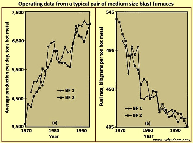
Fig 2 Bedrijfsgegevens van een typisch paar middelgrote hoogovens
Indeling van de BF
De lay-out van een BF is in wezen een oefening van het integreren van de apparatuur die nodig is om de verschillende materialen te verwerken die nodig zijn om ruwijzer te maken en het resulterende product en bijproducten. Het meest efficiënte ontwerp is geschikt voor het hele proces en de effectiviteit ervan wordt beoordeeld vanuit het oogpunt van zowel de initiële kapitaalinvestering als de lopende bedrijfskosten. De indeling van de BF-winkel is afhankelijk van verschillende factoren, zoals (i) terrein van de locatie, (ii) klimatologische omstandigheden, (iii) leveringsmethode van grondstoffen, (iv) verwerkingssystemen en locaties voor grondstoffen in de fabriek, (v) stroomafwaartse verwerkingssystemen en locaties, (vi) hoeveelheid / stroomvereisten voor ruwijzer, (vii) type en grootte van de leveringsvloot voor ruwijzer, en (viii) enzovoort. Fig 3 toont een vereenvoudigde lay-out van een BF-installatie.
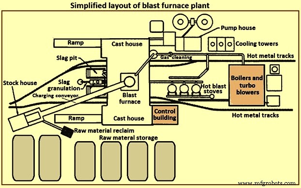
Fig 3 Vereenvoudigde lay-out van een hoogovenfabriek
Een BF-installatie bestaat doorgaans uit meerdere secties. Deze secties zijn (i) opslag, verwerking en terugwinning van grondstoffen, (ii) voorraadhuis, (iii) laadsysteem, (iv) eigenlijke oven, (v) gieterij, (vi) verwerking en behandeling van slakken, (vii) hantering van heet metaal, (viii) hete kachels en hete straalsysteem, (ix) gasreinigingsinstallatie, (x) nutsvoorzieningen, (xi) automatiserings- en controlesysteem, (xii) onderhoudsfaciliteiten en (xiii) personeelsondersteunende faciliteiten.
Opslag en verwerking van grondstoffen
Grondstoffen zoals ijzererts, sinter, pellets, vloeimiddelen, steenkool en cokes enz. worden ofwel van externe bronnen ontvangen ofwel geproduceerd in de geïntegreerde staalfabriek. Deze grondstoffen hebben voldoende gecontroleerde opslag nodig om de BF-operaties te ondersteunen. Opslagcapaciteit is nodig bij voorspelbare leveringsonderbrekingen of onvoorspelbare verstoringen. Bij eventuele wijzigingen in de bron van bepaalde grondstoffen kan extra opslagcapaciteit nodig zijn. Afzonderlijke opslaglocaties zijn nodig vanwege verschillende fysieke of chemische eigenschappen in vergelijkbare materialen. Het mengen van soortgelijke materialen kan procesbeheersing / metallurgische problemen veroorzaken. De opslagpalen moeten worden gescheiden om vermenging van de verschillende materialen te voorkomen. De palen moeten op voorbereide bedden worden geplaatst om de operators van de grondstofterugwinningsapparatuur in staat te stellen onderscheid te maken tussen prime- en tramp-materiaal. Er worden palen aangelegd om materiaaldegradatie tot een minimum te beperken en om het oppikken van fijne deeltjes door de wind te voorkomen. Watersprays en coconing-middelen kunnen worden gebruikt om stofopname / -afvoer door wind te minimaliseren.
Er zijn verschillende technieken beschikbaar voor het neerleggen en ophalen van grondstoffen. Aflegtechnieken zijn onder meer het kantelen van wagons, ertsbruggen, stapeltransportbanden, schrapers enz. Ophaaltechnieken omvatten graafwielreclaimers, buigmachines, frontladers, schrapers, rechtstreeks van bak- of stapelbodems enz. Het is duidelijk dat het neerleggen en ophalen systemen moeten worden gedimensioneerd om de doorvoer te garanderen die nodig is voor de BF-fabriek.
Voorraadhuis
Het voorraadhuis is de opslageenheid van de BF-operator voor directe aanvoer van de last naar de oven. Voor elk van de lastmaterialen voor de BF zijn er opslagbakken voorzien. Er zijn afzonderlijke bakken voorzien voor gelijkaardige materialen (d.w.z. sinter, pellets) met verschillende metallurgische eigenschappen. Het voorraadhuis zorgt voor voldoende capaciteit voor de verschillende laststoffen bij kortstondige bevoorrading vanuit de grondstoffenopslagplaatsen. Typische doorvoercapaciteiten van magazijnbakken, in het geval van verlies van grondstoftoevoer, zijn (i) cokes - 2 uur tot 8 uur, (ii) ijzerhoudende materialen (erts, sinter en pellets) - 4 uur tot 16 uur, en fluxen en andere diverse materialen - 8 uur tot 24 uur. Deze capaciteiten zijn gebaseerd op de nominale ovenproductie en variëren afhankelijk van de betrouwbaarheid en de toegangstijd voor vervanging uit voorraad of van een leverancier.
Lastige materialen hebben de neiging om af te breken als gevolg van klimatologische omstandigheden en herhaalde behandeling. Hoe hoger het aantal keren dat het materiaal wordt gehanteerd (voorraad aanleggen, terugwinnen, storten, transportkokers, ertsbrugemmers, enz.), hoe hoger het percentage boetes in de last. Het BF-proces heeft een gecontroleerde permeabiliteit en dus een gecontroleerde belasting nodig. Het laden van buitensporige boetes, ofwel normaal gedurende de hele lading of geconcentreerd over specifieke korte laadperioden, kan het BF-proces verstoren en schadelijk zijn voor de ovenapparatuur. Het voorraadhuis biedt de laatste redelijke mogelijkheid om boetes te verwijderen voordat ze in de oven worden geladen. Waar mogelijk worden trilzeven geïnstalleerd na de opslagbakken voor cokes, erts, sinter en pellets om het grootste deel van de boetes te verwijderen. De verwijderde boetes worden ingezameld voor recycling. Sommige BF-operators brengen boetes in rekening voor specifieke gebieden in de oven om de lokale permeabiliteit van de oven aan te passen en de warmtebelasting op de ovenwanden te regelen.
Vochtmeters zijn vaak aanwezig in het voorraadhuis om de werkelijke waterhoeveelheden die in de oven worden geladen te controleren. Met deze informatie kunnen de oplaadhoeveelheden worden aangepast om de wisselende omgevingsomstandigheden te compenseren (d.w.z. hoger cokesvocht tijdens de regenperiode).
Aangezien verschillende soorten en variërende hoeveelheden van het belastingsmateriaal nodig zijn om de continue werking van de BF te ondersteunen, moeten de belastingsmaterialen in een specifieke volgorde worden geleverd (die zelf vaak kan worden gewijzigd om de variërende bedrijfsparameters van de oven te ondersteunen). Daarom moet de veestapel worden voorzien van betrouwbare apparatuur voor het extraheren en voeren van nauwkeurige hoeveelheden specifiek lastmateriaal om aan een specifiek schema te voldoen. Afb. 4 toont een vereenvoudigde opstelling van de uitrusting in de veestapel.
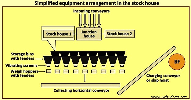
Fig 4 Vereenvoudigde apparatuuropstelling in het magazijn
Vroeger was het meest voorkomende type voorraadhuis het highline-type. Dit type voorraadhuis bevindt zich direct naast de oven. Treinwagons of brugkranen voeden de opslagbak terwijl de opslagbakken rechtstreeks naar een rijdende schaalwagen worden gevoerd. Een machinist van een weegschaal bestuurt handmatig de afvoerpoort van de bak om specifieke hoeveelheden materiaal in de met weegschaal uitgeruste trechter in de weegschaalwagen te voeren. Na het verzamelen van de juiste soorten en hoeveelheden materiaal, verplaatst de machinist de schaalwagen naar een positie boven de 'skip pit' en dumpt de last, via een parachute, in een wachtende skipwagen. De kiepwagen wordt dan naar de bovenkant van de oven gehesen.
Het highline-type voorraadhuis, in combinatie met een schaalwagen, heeft weinig opties opgeleverd voor het leveren van het zeven van ijzerhoudende lading (erts, sinter en pellets). Naarmate de kennis van het BF-proces is toegenomen, zijn er strengere eisen aan de last ontwikkeld. Het concept van 'engineered load' wordt tegenwoordig algemeen erkend in de industrie. Het wordt normaal aanvaard dat er grenzen zijn aan de flexibiliteit en het aanpassingsvermogen van het highline-veebedrijf om aan deze eis te voldoen. Vandaar dat het highline-type van de opslagplaats is vervangen door het geautomatiseerde magazijn met transportband voor het leveren van laadmateriaal aan de BF.
Het geautomatiseerde magazijn bestaat normaal gesproken uit twee verschillende en verschillende typen. Het eerste type is de vervanging van de weegwagen onder de grondstofbakken door een aanvoer- en transportbandsysteem. Voor elk type grondstof (cokes, ijzerhoudende materialen en fluxmaterialen en additieven enz.) zijn afzonderlijke transportbanden voorzien waarover rijen opslagbakken zijn gemonteerd, met trillende feeders om lastmaterialen van opslagbakken naar transportbanden te lossen. Voor de cokes- en ijzerhoudende materialen bevindt zich een trilzeef bij de afvoer van elke transportband om het materiaal te zeven en het gezeefde materiaal in de weeghoppers te voeren. Dit type systeem blijft de weeghoppers voor de kiepwagens voeden.
Het tweede type van het geautomatiseerde magazijn is een grote structuur van opslagbakken die volledig bovengronds en vrij weg van de BF is gebouwd. Dit wordt normaal gesproken gedaan voor de BF's waar een bandtransporteur wordt gebruikt om de lastmaterialen naar de bovenkant van de oven te dragen in plaats van de overslaande auto's. De methode voor het vullen van de opslagbakken is normaal gesproken door middel van een transportbandsysteem. De grondstoffen worden uit de voorraadbakken gehaald door middel van vibrerende feeders en bandtransporteurs in weeghoppers. De weeghoppers lossen het materiaal op hun beurt door middel van een opvangband op de hoofdband. De weeghoppers zijn geprogrammeerd om de grondstoffen in de juiste volgorde op de hoofdtransportband naar de bovenkant van de oven te wegen.
Het voorzien van een geautomatiseerd voorraadhuis kan zorgen voor een efficiëntere toevoer van grondstof naar het voorraadhuis en een efficiëntere selectie, screening, weging en levering van de last aan de oven. Het geautomatiseerde stapelhuis kan direct naast de ovenwagen worden geplaatst, of kan op afstand van de oven worden geplaatst om via een transportband te worden gevuld.
De automatisering van het magazijn heeft de productiecapaciteit aanzienlijk vergroot, de bedrijfsefficiëntie verbeterd en de operationele afwijkingen veroorzaakt door operators en apparatuur geëlimineerd. In de praktijk kan een modern, geautomatiseerd magazijn echter behoorlijk complex zijn. Het voorraadhuis zelf kan worden gevoed door transportbanden, die op hun beurt worden afgevoerd op struikelbanden om materialen naar verschillende bakken te verdelen. De indeling van transportbanden en apparatuur in het magazijn kan op een groot aantal manieren worden geregeld. Plaatsing van het voorraadhuis naast de oven resulteert vaak in opstoppingen in de lay-out en beperkt de flexibiliteit voor toekomstige wijzigingen.
Hijssysteem
De lastmaterialen worden normaal gesproken met behulp van kiepwagens of met een transportband naar de BF-top gehesen.
Auto hijsen overslaan – Het gebruik van de skip-auto voor BF is voortgekomen uit de mijnbouw. BF-containerwagens zijn gedimensioneerd om te passen bij de doorvoer van de oven. Het is duidelijk dat verschillende factoren, zoals de hijscapaciteit, het ontwerp van de laadbrug, enzovoort, hun eigen invloeden of beperkingen hebben op de grootte van de laadbak.
Normaal gesproken werken twee laadkleppen in tegengestelde richting (om het benodigde hijsvermogen te verminderen) op een gemeenschappelijke takel. Skips rijden op rails op een skip-brug, normaal geïnstalleerd met een helling van ongeveer 60 graden tot 80 graden ten opzichte van horizontaal. De volle laadbak versnelt langzaam wanneer deze de laadbak verlaat, versnelt zo snel mogelijk en bereikt en rijdt met maximale snelheid voor het grootste deel van de lift. De takel vertraagt de laadbak naarmate deze de bovenkant van de laadbrug nadert. De wielen van de bak worden geleid door de stort- en hoornrails wanneer de bak wordt gekanteld in de laadapparatuur van de oven. Terwijl de hijscontainer de uiteindelijke stortpositie bereikt en stopt, bereikt de lege container (die met dezelfde snelheden daalt) net de bodem van zijn reis naar de container, in afwachting van vulling. Het laadsysteem voor overslaan is een betrouwbare en effectieve techniek om de last naar de oven te brengen. Het ontbreekt echter aan flexibiliteit voor de machinist, omdat de laadbakken slechts een bepaalde hoeveelheid materiaal kunnen bevatten (overbelasting resulteert in overvulling of buitensporige hijsbelastingen) of inefficiënt wordt als kleine hoeveelheden specifieke last nodig zijn. Fig 5 toont een schematische weergave van het hijsen van een laadbak.
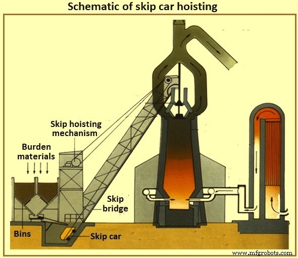
Fig 5 Schematische voorstelling van het hijsen van een laadbak
Oven laadband – Met het transporteren van het voorraadhuis is het transporteren van het hijssysteem gekomen. Het is nu gebruikelijk dat de voorraadhuizen op afstand van de oven zijn geplaatst en één grote transportband draagt de last naar de bovenkant van de oven. Als de bovenkant van de oven ongeveer 60 meter hoog is, dan moet een transportband worden geïnstalleerd met een helling van 8 graden naar horizontale positie, het voorraadhuis moet op minimaal 427 meter van de oven worden geplaatst. Steilere hellingen van de riem worden normaal gesproken vermeden om het terugrollen van materiaal te minimaliseren. Het is normaal om diverse materialen direct over en na het einde van een ijzerhoudende lading op de transportband te laden om de ijzerhoudende materialen op hun plaats te houden totdat ze de bovenkant van de oven bereiken.
Oplaadsysteem aan de bovenkant van de oven
De eigenlijke oven wordt bedreven met positieve hoge topdruk. BF-gas dat gedeeltelijk bestaat uit koolmonoxide, kooldioxide en stikstof wordt gegenereerd door het BF-proces samen met grote hoeveelheden meegesleept stof. De BF-operator moet de topdruk handhaven vanwege de procesvoordelen en de gassen en het stof vasthouden (zowel voor brandstofwaarde als voor milieucontroledoeleinden). De operator moet echter regelmatig lastmateriaal in de bovenkant van de oven plaatsen om het interne proces aan te vullen, zonder de topdruk van de oven te verliezen.
Beltype bovenaan – Sinds enkele jaren is het meest voorkomende type ovenblad het blad met twee klokken (afb. 6). Wanneer de last de bovenkant van de oven bereikt (door een kiepbak of door een transportband), valt deze in een opvangtrechter en in de kleine kloktrechter. De kleine klok (conisch gevormd stalen gietstuk met een diameter van ongeveer 2,6 meter en een hoogte van 1,4 meter voor een BF van 5.000 tHM per dag) zakt en laat de last in de grote kloktrechter vallen. De kleine bel wordt opgetild en sluit af tegen een vaste zitting op de kleine kloktrechter. Afhankelijk van het volume van de grote kloktrechter worden extra lasten door de kleine klok in de grote klokkentrechter gebracht. Gedurende dit proces is de grote klok gesloten gebleven, waardoor de oven werd afgesloten. Wanneer de juiste aantallen last van de last zijn verzameld, zakt de grote klok (kegelvormig gegoten staal met een diameter van ongeveer 5,5 meter en een hoogte van ongeveer 3,5 meter voor een BF van 5.000 tHM per dag) en laat de last langs de klok naar beneden glijden. de bovenkant van de oven zelf. Na het lossen van de last wordt de grote klok geheven en sluit deze af tegen de onderzijde van de grote kloktrechter. Afb. 6 toont beltype BF toplaadsystemen.
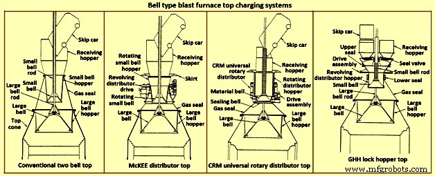
Fig 6 Bell-type hoogoventoplaadsystemen
Het is duidelijk dat de controle van de lastverdeling met de oven voor dit type blad wordt beperkt door hoe gelijkmatig de last op de grote bel wordt geplaatst (skip-dumping resulteert in ongelijkmatige plaatsing van last in dit type blad) en de dalende rondingen van de specifieke lastmaterialen (d.w.z. cokes of ijzerlading) als ze van de grote bel glijden en vallen. Verder is de bovenkant van de twee klokken gevoelig voor verlies van afdichting van de grote en kleine klokken en van de pakking tussen de grote klokstang en de kleine klokbuis. Kloklekkage is het gevolg van de slijtage door het belaste materiaal dat over de klokafdichtingsoppervlakken glijdt. De lekkage van de stangpakking is het gevolg van slijtage door fijne deeltjes, hetzij vanuit de oven, of door het verzamelen op de grote klokstang nadat de last in de opvangtrechter is gestort.
In een poging om slijtage van het afdichtingsoppervlak van de grote klok te minimaliseren, wordt BF-gas dat uit de oven wordt gehaald tussen de klokken ingebracht om de ruimte gelijk te maken (het drukverschil over het afdichtingsoppervlak van de grote klok wordt verminderd). Dit gas wordt afgevoerd naar de atmosfeer voordat de kleine bel wordt geopend om de introductie van meer last mogelijk te maken. Enkele van de beschikbare opties om de beperkingen van het topsysteem met twee bellen te verbeteren, worden hieronder gegeven.
De McKEE-distributeur – De McKEE-verdeler (afb. 6) was gedurende meerdere jaren de belangrijkste verbetering van de lastverdeling die beschikbaar was voor de top met twee klokken. Het wordt echter snel vervangen door andere technologieën. Het ontwerp omvat de mogelijkheid om de kleine bel en de kleine kloktrechter samen te draaien terwijl de kiepwagen aan het lossen is. De last wordt gelijkmatig verdeeld in de kleine kloktrechter, waardoor de belasting gelijkmatig op de grote klok wordt geplaatst. Dit type blad is gevoelig voor slijtage van kleine en grote klokken en daardoor verlies van afdichtingseffect.
CRM universele roterende verdeler boven – CRM (Centre Recherches Metallurgiques – België) universele roterende verdeler (Fig 6) werd ontwikkeld om het verlies van het kleine klokje-afdichtingseffect te elimineren. Twee bellen (een afdichtingsbel en een materiaalbel) zijn geïnstalleerd in plaats van de normale kleine bel. Op de materiaalbel is een draaiende lasttrechter gemonteerd. De afdichtingsklok bevindt zich onder de materiaalklok en sluit af tegen een vaste zitting. Tijdens het lossen van de container worden de laadtrechter en de gesloten materiaalbel gedraaid om de trechter gelijkmatig te vullen. Wanneer het vullen is voltooid, stopt de rotatie van de trechter. Wanneer het tijd is om op de grote klok te storten, worden de draaiende trechter, materiaalklok en afdichtingsklok neergelaten. De afdichtingsklok zakt onder de vaste zitting. Halverwege het daalproces wordt het dalen van de trechter gestopt en blijven de materiaalbel en afdichtingsklok dalen totdat ze hun stoppositie bereiken. Naarmate de opening tussen de materiaalbel en de trechter opengaat, wordt de last gelijkmatig in de grote trechter afgevoerd. Als de last de opening verlaat, komt deze niet in contact met het zittingsoppervlak van de afdichtingsklep, waardoor het topafdichtingsvermogen behouden blijft. Deze topstijl kan een interne druk van 0,2 MPa aan.
De CRM-top verbetert het afdichtingsvermogen en de levensduur van de top met twee klokken. Het zorgt echter niet voor een dramatische verbetering van de verdeling van de ovenbelasting ten opzichte van de McKEE-distributeur en elimineert niet de kwetsbaarheid van het grote belafdichtingsoppervlak.
De GHH lock hopper top – De GHH lock hopper top (Fig 6) is de modificatie van de two-bell top. Het vermindert de afhankelijkheid van de grote bel om een gasafdichting te behouden. De toevoeging van sluistrechters met afzonderlijke afdichtingskleppen voor elke stortplaats voor kiepbakken biedt een extra capaciteit voor het afdichten van de bovenkant. De grote klok kan worden bediend zonder verschildruk over het afdichtingsoppervlak (d.w.z. de topdruk van de oven is gelijk aan de druk van de grote kloktrechter). De werking wordt hieronder gegeven.
Een kiepbak dumpt de last in de sluistrechter via een opvangtrechter en een open afdichtingsklep. De last wordt op de roterende kleine klok gelegd en vult gelijkmatig de roterende verdeeltrechter boven de kleine klok. Een afdichting tussen de sluistrechter en de roterende kleine kloktrechter is open terwijl de rotatie aan de gang is. Wanneer het lossen van de last uit de bak is voltooid, worden de afdichtingsklep en de afdichting tussen de sluistrechter en de kleine kloktrechter gesloten. Egalisatiegas wordt ingebracht en de sluistrechter wordt onder druk gebracht tot de topdruk van de oven. De kleine klok wordt vervolgens neergelaten om de last in de grote kloktrechter te brengen. De kleine bel sluit en de druk van de sluistrechter wordt afgelaten naar de atmosfeer. De afsluitklep aan de andere kant (d.w.z. aan de andere kant van het kiepen) wordt geopend. De afdichting tussen de sluistrechter en de kleine kloktrechter wordt geopend. Rotatie van de kleine bel en hopper begint. De top kan nu de last van de andere skip accepteren.
Dit type top verbetert de afdichting en de levensduur van de twee klokken. De bovenkant van de sluistrechter biedt echter geen dramatische verbetering van de verdeling van de ovenlast ten opzichte van de McKEE- of CRM-top. Hoewel de grote bel niet langer nodig is om een afdichtingsfunctie uit te voeren, is de levensduur van de kleine stolp nog steeds van cruciaal belang.
Beweegbaar pantser – De belangrijkste stap die is gezet om de lastverdeling van de top van het beltype te verbeteren, was de ontwikkeling van beweegbare bepantsering (Fig. 7). In het keelgebied van de oven zijn verstelbare deflectors geïnstalleerd om de last af te buigen nadat deze van de grote bel is geschoven. Het beweegbare pantser wordt aangepast afhankelijk van het specifieke lastmateriaal dat wordt afgevoerd en waar de operator de last in de oven wil plaatsen.
Verschillende fabrikanten bieden verschillende soorten beweegbare bepantsering. Individuele pantsersegmenten kunnen gelijkmatig (gelijktijdig en gelijkmatig) in de oven worden bewogen om de last in een ringvormig patroon te plaatsen. Er zijn andere soorten beweegbare bepantsering beschikbaar om individuele controle over de pantserplaten te bieden om een niet-cirkelvormig distributiepatroon te bereiken.
Enkele nadelen verbonden aan beweegbare bepantsering zijn (i) het merendeel van de mechanische en slijtagecomponenten ligt in de ruwe omgeving van de topconus van de oven, (ii) enig verlies van intern werkvolume is nodig om ruimte te creëren tussen de beweegbare bepantsering en de ontwerp-stockline niveau (hoewel dit gebied van de oven niet kan worden geclassificeerd als een ruwe productiviteitszone voor het in aanmerking nemen van het werkvolume van de oven, en (iii) beperkt vermogen om de last naar het midden van de oven af te leiden, vooral wanneer het voorraadniveau al hoog is. kenmerk van pellets doet vaak de beperkte verplaatsing van het beweegbare pantser teniet.
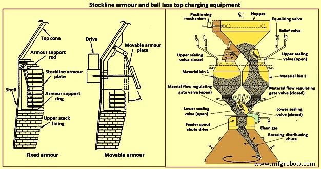
Fig 7 Stockline pantser en belloze toplaadapparatuur
Blokloos laadsysteem aan de bovenkant – In het begin van de jaren 70 ontwikkelde Paul Wurth S.A. uit Luxemburg het oplaadsysteem zonder bel (BLT) (Fig 7). Dit type oventop is een radicale afwijking van de top van het beltype. Last kan in de oven worden geplaatst in elk patroon dat de ovenoperator nodig heeft. De plaatsing van ringvormige ringen, spiralen, segmenten en punten is een veelvoorkomend patroon dat kan worden bereikt door gesynchroniseerd of onafhankelijk kantelen en roteren van een stortkoker die zich bij de bovenste kegel van de oven bevindt.
De afdichting van de bovenzijde van de oven wordt gehandhaafd gedurende de hele campagne van de oven. Onderhoudswerkzaamheden zijn eenvoudig en van korte duur. Normaal gesproken bestaat de BLT uit een stortkoker of trechter (ontvangende last van de kiepbakken of van een transportband), een sluistrechter met bovenste en onderste afdichtingskleppen, een materiaalstroomcontrolepoort, een hoofdchute-aandrijfversnellingsbak (een water- of -gekoelde unit gebruikt voor het draaien en kantelen van de stortkoker) en de lastverdeelkoker. Er zijn drie hoofdtypen BLT, namelijk (i) parallelle hopper, (ii) centrale invoer en (iii) compact type.
Typisch omvat het parallelle type twee sluistrechters (de trechters zijn op sommige ovens geïnstalleerd voor doorvoer- en back-updoeleinden; er is één 'excentrisch' trechtertype geïnstalleerd voor een toepassing met beperkte speling). Sinds het begin van de jaren tachtig hebben verschillende BF's het type 'centrale invoer' met een enkele sluis gekozen vanwege de verbeteringen in de scheiding van de lasten en de beheersing van de lastverdeling, resulterend in een verbeterde werking van de oven.
Er is een 'compact' type BLT-top ontwikkeld voor kleine tot middelgrote ovens om de introductie van de BLT (en de voordelen ervan) in ovens mogelijk te maken waar de andere grotere typen BLT's vanwege de kosten of fysieke beperkingen niet kunnen worden gebruikt. De stappen in BLT-bedrijf voor een centraal voertype zijn (i) de last wordt afgevoerd van een kiepbak of transportband via een stortkoker of trechter langs een open afdichtingsklep in de sluistrechter, (ii) nadat de last is ontvangen in de sluis trechter, wordt de bovenste afdichtingsklep gesloten en wordt egalisatiegas ingevoerd om de sluistrechter onder druk te zetten tot ovendruk, (iii) de onderste afdichtingsklep gaat open, (iv) de last wordt afgevoerd uit de sluistrechter wanneer de materiaalpoort is ingesteld op de voorgeselecteerde opening die past bij het specifieke te lossen lastmateriaal, (v) de last valt verticaal door de invoertuit met de hoofdtransmissie en valt op de lastverdeelgoot, (vi) de lastverdeelgoot richt de last naar de vereiste point(s) within the furnace, (vii) when the lock hopper is fully discharged (monitored by load cells and / or acoustic monitoring), the lower seal valve is closed, (viii) a relief valve is opened to exhaust the lock hopper to atmosphe re (or through an energy recovery unit), and (ix) the upper seal valve opens and the sequence is repeated.
The advantages of BLT over other top charging systems include higher top pressure capability (i.e. 0.25 MPa), fuel savings, increased production, more stable operation, reduced maintenance in terms of cost and time, increased furnace campaign life, and improved furnace operational control when employing high coal injection rates at the tuyeres.
Gimbal system of charging – The purpose of the Gimbal system of charging is to facilitate controlled distribution of charge material into the BF via a Gimbal type oscillating chute through a holding hopper and variable material gate opening such that the pressurized charging system above can operate independently of the distribution system. It utilizes a conical distribution chute, supported by rings in a Gimbal arrangement, producing independent and combined tilting of the chute axis. The Gimbal distributor, as part of the overall BF top charging system, offers a fully integrated charging solution, generating considerable improvement in BF operation and maintenance cost. The Gimbal system utilizes a conical distribution chute, supported by rings in a Gimbal arrangement, producing independent, and combined tilting of the chute axis.
The Gimbal top incorporates a full complimentary range of furnace top distribution equipment including distribution rockers, upper seal valves, hoppers, lower seal valves, material flow gates and goggle valve assemblies, all discharging through hydraulically driven distribution chutes. The tilting chute is driven by two hydraulic cylinders, mounted 90 degree apart. This type of suspension and drive arrangement results not in a rotation of the tilting chute, but in a circular path by superposition of both tilting motions. Independent or combined operation of the cylinders allows the chute axis to be directed to any angle, or even along any path. Motion is supplied by two hydraulic cylinders, each operating through a shaft, connecting rod, and universal joint in order to drive the Gimbal rings. Through the movement of the hydraulic cylinders, the distribution chute allows precise material distribution with potential for an infinite number of charging patterns at varying speeds. These include ring, spiral, centre, spot, segment or sector charging, providing complete control of material charging into the furnace.
The whole distributor assembly is enclosed in a gas tight housing, which is mounted directly onto the top flange of the BF top cone. The housing contains a fixed inlet chute and a tilting distribution chute supported by rings in a Gimbal arrangement allowing independent and combined tilting of the chute axis. The assembly is made from a combination of stainless and carbon steel material with the fixed inlet chute and tilting chute body lined with ceramic material to give superior wear protection. A closed-circuit water cooling system supplies cooling water through the main shafts, Gimbal bearings, and universal joint bearings in order to cool the moving elements of the Gimbal distribution system.
The key features of the Gimbal design are (i) simple, rugged design, using levers driven by the hydraulic cylinders, (ii) drive cylinders are mounted outside pressure envelope, hence not subject to hot and dusty service conditions, (iii) Gimbal ring arrangement gives simple tilting motion in two planes, which when superimposed gives 360 degrees distribution, and (iv) wear on the tilting chute is equalized around its circumference giving a long extended operational life.
The BF Gimbal top is an automated, computer-controlled pressurized charging system designed to (i) receive charges of ore, coke, and miscellaneous materials in the holding hopper, independently of the distribution system below, (ii) release those discharges, as needed, to a dynamic distribution chute located below the holding hopper, and (iii) distribute material in prescribed patterns to the furnace stock-line in accordance with a predetermined charging matrix. Control of the Gimbal distribution chute is fully integrated into the overall furnace charging software. The system provides a high level of accuracy and control for the Gimbal movements and hence the positioning of the distribution chute. Gimbal material distributor is shown in Fig 8.
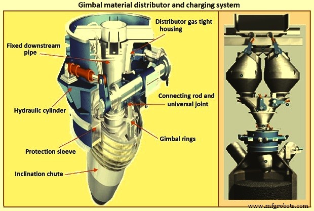
Fig 8 Gimbal material distributor and charging system
Furnace proper
The furnace proper is the main reactor vessel of the BF ironmaking process. Its internal lines are designed to support the internal process. Its external lines are designed to provide the necessary systems to contain, maintain, monitor, support, and adjust the internal process.
The BF process is a counter flow process. The process comprises of (i) burden at ambient conditions is placed in the furnace top onto the column of burden within the furnace, (ii) as the burden descends with the burden column, it is heated, chemically modified, and finally melted, (iii) further chemical modifications occur with the molten material, (iv) the molten products are extracted near the bottom, (v) melting of the burden material and extraction result in the descent of the burden column and the need for replenishment of the burden at the top, (vi) hot blast air is introduced through tuyeres near the bottom, (vii) BF gases are generated in front of the tuyeres and ascend through the burden and chemically modify the descending burden as well as themselves get chemically modified and cooled, (viii) BF gas (and dust) is extracted near the top of the furnace, and (ix) heat is extracted from the vessel in all directions (primarily through the lining cooling system) and along with the BF gas, liquid iron and liquid slag. Fig 9 shows cross section and types of BF.
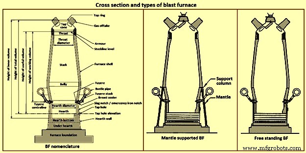
Fig 9 Cross section and types of blast furnace
Furnace type – Furnaces are constructed to be mantle supported or free standing. Mantle supported BFs characteristically have a ring girder (mantle) located at the bottom of the lower stack of the furnace. The mantle is supported in turn by columns which are on the main furnace foundation. The hearth, tuyere breast, and bosh are also supported by the foundation. Furnaces with mantle support column tend to have restricted access and reduced flexibility for improvements in the mantle, bosh, and tuyere breast areas.
Since thermal expansion is a major consideration in furnace shell design, the mantle style of furnace provides an interesting design consideration. The mantle support columns are relatively cool. The mantle tends to maintain a constant height, throughout the furnace campaign with respect to the furnace foundation. Thermal expansion of the stack due to process heat is considered to be based at the ‘fixed’ mantle (i.e. the top of the furnace raises with respect to the mantle). The effective height of the bosh, tuyere breast, and hearth wall shells (supported on the furnace foundation) increases due to the thermal expansion of the shell caused by the process heat. The lower portion of the furnace lifts upwards towards the fixed mantle. Hence, the provision of an expansion joint of some type is needed at the bosh / mantle connection or somewhere appropriately located in the lower portion of the furnace.
Free standing furnaces have been developed to eliminate the column and permit the installation of major equipment and furnace cooling improvements. This furnace type has a thicker shell for structural support. Installation and maintenance of a reliable cooling and lining system is necessary in order to sustain the structural longevity of the shell.
Two variations of the free standing furnace have been used. One type provides for a separate structural support tower to carry the furnace off-gas system and charging / hoisting system load. The other type (while it does employ a separate support tower for shell replacement purposes during relines) uses the furnace proper to support the off-gas system and charging / hoisting system loads. Special consideration to the furnace shell design is to be made regardless of the furnace type. The furnace vessel is subjected to internal pressures from the blast and gas, burden, liquid iron and slag. Dead and live load during all operating, maintenance, and reline stages are to be considered as well.
Furnace zones – The major zones of the furnace proper are (i) top cone, (ii) throat, (iii) stack, (iv) mantle / belly, (v) bosh, (vi) tuyere breast, (vii) hearth walls, (viii) hearth bottom, (ix) foundation.
Top cone – The top cone or dome is the uppermost part of the furnace proper. It supports the furnace top charging equipment, and the BF top gas collection system. Stock rods (stockline recorders or gauges) are normally placed here to monitor the upper level of the burden in the furnace. These devices are the units which provide the permissive or indication signals to charge the next scheduled burden input to the furnace. Typically, they are weights lowered by special winches, or microwave units. Some furnaces incorporate radio-active isotope emitters and detectors mounted in the furnace throat to monitor the burden level. Infrared camera can be installed in the top cone to monitor the BF top gas temperature distribution as it escapes the furnace burden stockline.
The top cone is the coolest zone of the furnace proper but can be exposed to extremely high temperatures if burden ‘slips’ (rapid, uncontrolled burden descent after a period of unusual lack of descent). The newly charged burden falls through this zone and the BF top gas is carried away from this section.
Throat – Steel wear plates or armour are installed in this zone. Here, abrasion of the furnace lining from the charged burden is the prime cause of deterioration. Furnace operators work to maintain the upper level of the burden (the stockline) in this region. Movable armour can be installed in this area in order to deflect the burden falling from a large bell. With the installation of the BLT, wear of the stockline area can be greatly reduced. Some BF users select to eliminate the armour plates and use an abrasion resistant refractory lining instead.
Stack – The stack (sometimes called shaft or the ‘in-wall’) is the zone between the mantle or belly on a free standing furnace and the stockline area. Smooth, uniform lines (the process ‘working surface’) of the stack are essential for uniform and predictable burden descent, BF gas ascent, and stable process control throughout the furnace campaign. Process considerations dictate a larger diameter at the base of the stack than at the top. Typical stack angles are in the range of around 85 degrees from the horizontal.
Mantle / belly – The mantle or belly area provides the transition between the expanded stack and bosh sections. Maintenance of the effectiveness of the cooling / lining system is particularly important for the mantle type furnace in order to protect the mantle structure. Thermal protection is important for the free standing furnace type as well. However, the free standing design is less complicated and more accessible in this area.
Bosh – The bosh area lies between the tuyere breast and the mantle / belly of the furnace. The bosh diameter increases from bottom to top. The inclination of the bosh permits the efficient ascent of the process gases and has been found to be necessary in order to provide the needed zone service life (the process gases are extremely hot and internal chemical attack conditions are severe). Typical bosh angles are in the range of around 80 degrees from the horizontal. Boshes are of two basic types, namely (i) banded and (ii) sealed. They can be cooled by different techniques.
Banded boshes are found in older mantle supported furnaces (they cannot be applied to free standing furnaces). A number of steel bands are placed in incrementally increasing diameters (smallest at the bottom of the bosh and largest at the top) and are tied together with connecting strips. Gap between the bands permits the introduction of copper cooling plates. Ceramic brick lining is to be used as air infiltration results in oxidation of carbon based linings. Gas leakage through the banded bosh can be high. This type is not suitable for BFs with high blast pressure / high top pressure. Banded boshes provide adequate flexibility to eliminate the requirement for a shell expansion joint in the lower portion of the furnace.
Sealed boshes, using continuous steel shell plate instead of separate bands, are employed to permit the use of improved cooling / lining systems, higher furnace operating pressures, and the free standing furnace type. Sealed boshes retain valuable gases with the furnace, hence improving the metallurgical process. As well, the seal bosh, since it precludes air entry into the lining, supports the use of carbon based refractories.
Tuyere breast – Hot blast air is introduced to the furnace through tuyeres (water-cooled copper units) located within the tuyere breast. The number of tuyeres needed depends upon the size (production capacity) of the furnace. The tuyere breast diameter, tuyere spacing, and number of tuyeres are influenced by the expected raceway zone size in front of each tuyere.
Tuyere stocks (Fig 10) convey the hot blast air from the bustle pipe to the tuyeres. The tuyeres are supported by tuyere coolers (water-cooled copper units) which are in turn supported by steel tuyere cooler holders (either welded or bolted to the furnace shell). Special consideration are to be made in the tuyere breast shell and lining design in order to maintain effective sealing of the different components in order to prevent escape and loss of the furnace gases.
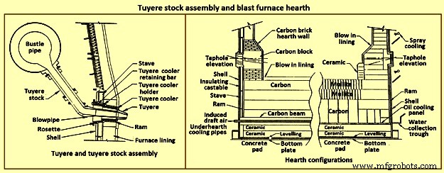
Fig 10 Tuyere stock assembly and blast furnace hearth
Hearth – The hearth (Fig 10) is the crucible of the furnace. Here, hot metal and liquid slag are collected and held until the furnace is tapped. The hearth wall is penetrated by tap holes (frequently called iron notches) for the removal of the collected hot metal and liquid slag. The number of tap holes is dependent upon the size of the furnace, hot metal, and liquid slag handling requirements, physical and capital constraints etc.
Several furnaces are equipped with a slag or cinder notch (normally one per furnace, although some furnaces can have two). The slag notch opening elevation is normally sufficiently higher than the iron notch elevation. In earlier days, when slag volumes were high, the slag was flushed from the slag notch periodically. This simplified the iron / slag separation process in the cast house. More commonly now, however, the slag notch is retained solely for initial furnace set-up procedures or for emergency use in case of iron notch or other furnace operating problems.
Hearth bottom – The hearth bottom supports the hearth walls and is flooded by the iron within the furnace. As the campaign progresses, the hearth bottom lining wears away to a fixed equilibrium point. The remaining refractory contains the process and with sufficient cooling or inherent insulation value protects the furnace pad and foundation.
Cooling system
The application of specific cooling techniques to individual furnace zones is dependent upon several factors such as campaign life expectancy, furnace operational philosophy, burden types, refractories, cost constraints, physical constraints, available cooling media, and preferences etc. Different cooling techniques can be provided for different zones to assist the lining to resist the specific zone deterioration factors. Normally, the provision of adequate cooling capacity is necessary in each of the applicable furnace zones if the lining system located there is to survive. Where the thermal, chemical, and to some extent the abrasive conditions of the process are extreme, sufficient cooling is to be provided to maintain the necessary uniform interior lines of the furnace and to protect the furnace shell.
Typically, the top cone and throat areas of the furnace are not cooled. The hearth bottom can be ‘actively’ cooled by under hearth cooling (air, water, or oil media) or ‘passively’ cooled by heat conduction though the hearth bottom lining to the hearth wall. The basic cooling options for the balance of the furnace are (i) no cooling (typically the upper portion of the stack is not cooled in several furnaces, (ii) shower or spray cooling, (iii) jacket or channel cooling, (iv) plate cooling, and (v) stave cooling.
Shower or spray cooling – Water is directed by sprays or by overflow troughs and descends in a film over the shell plate. Effective spray nozzle design, numbers and positioning are important for proper coverage and to minimize rebound. Proper deflector plate design is necessary to ensure efficient cooling water distribution and to minimize splashing. Shower cooling is frequently employed in the bosh and hearth wall areas. Spray cooling is normally applied for emergency or back-up cooling, primarily in the stack area. Exterior shell plate corrosion and organic fouling are common problems which can disrupt water flow or insulate the shell from the cooling effect of the surface applied cooling. Water treatment is an important consideration to retain effective cooling.
Jacket or channel cooling – Fabricated cooling chambers or indeed structural steel channels or angles are welded directly to the outside of the shell plate. Water flows at low velocity though the cooling elements in order to cool the shell and the lining. Jacket or channel cooling is frequently applied to the hearth walls, tuyere breast, and bosh areas. Scale build-up on the furnace shell and debris collection in the bottoms of the external cooling elements can compromise the cooling effectiveness. Hence periodic cleaning of the cooling elements is necessary.
The critical area of concern in the cooling schemes mentioned so far is the necessity for the shell plate to act as a cooling element. If extreme heat loads are acting upon the inside face of the shell, then there exist an extremely high thermal gradient across the shell. This effect results in high thermally induced shell stresses and eventual cracking. The cracks start from the inside of the furnace and propagate to the outside. The cracks remain invisible (other than a ‘hot spot’) until they fully penetrate the shell plate. Through cracking of the shell plate results in the leak of the BF gas, exposed shell carburization, and disruption of the cooling effect (particularly spray or shower cooling). Shell cracking into a sealed cooling jacket or channel is difficult to locate and can result in long furnace outage time for repair. Entry of water into the furnace (frequently when the furnace is off-line and internal furnace gas pressure cannot prevent entry of cooling water though shell cracks) can have detrimental effect upon the furnace lining. Water in the furnace can be potentially dangerous due to explosion risk (steam or hydrogen). Since shower and jacket cooling rely on the shell plate to conduct the process heat to the cooling media, the plate and stave cooling are configured to isolate the shell from process.
Plate and cigar cooling – Installation of cooling elements though the shell of the furnace (Fig 11) has been a major furnace design improvement resulting in effective cooling of the furnace lining and protection of the shell plate. Cooling is provided along the length of the cooling element penetration into the lining. The inserted elements provide positive mechanical support for the refractory lining. Typical cooling plate manufacture is cast high conductivity copper. Single or multiple passes of cooling water can be incorporated. Cooling boxes with larger vertical section have been produced from cast steel, iron, or copper.
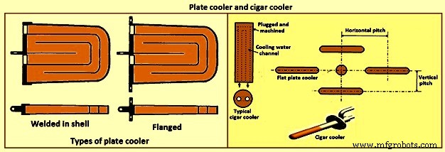
Fig 11 Plate cooler and cigar cooler
Cigar type (cylindrical) coolers (Fig 11) of steel and /or copper have also been successfully used. The philosophy of dense plate cooling (i.e. vertical pitch of 350 mm to 400 mm centre-to- centre, and horizontal pitch of 600 mm (centre-to-centre) has improved the cooling effect and increased lining life.
Copper cooling plates have traditionally been anchored in the shell plate with retainer bars or bolted connections to permit ready replacement if plate leakage occurs. More recently, plates have been designed with steel sections at the rear of the plate for welding directly to the steel shell. While sometimes taking longer to replace, this type provides a positive seal against BF gas leakage. Plate coolers are typically installed in areas above where the liquid iron collects in the furnace. Hence the mid-point of the tuyere breast, right up to the underside of the throat armour is the range of application.
Stave cooling – Cast iron cooling elements (Shannon plates or staves) have been used for several years in the bosh and hearth wall areas. These castings have cored cooling passages of large cross-section. While their service life have been not remarkable in the bosh, multiple campaigns have been normal for the hearth wall. These staves frequently suffered from low flow rates of marginal quality cooling water (scaling and debris deposition / build-up) and sometimes casting porosity. Water leaks into the hearth wall can be a considerable problem.
In the 1950s, the then USSR developed a new type of stave cooler (Fig 12) and ‘natural evaporative stave cooling’. For this design, castings were of gray cast iron containing steel pipes for water passes. The pipes were coated prior to casting to prevent carburization of the cooling pipe and metallurgical contact with the stave body material. The staves were installed in horizontal rows with the furnace and the cooling pipes projected through the shell. Vertical column of staves were formed by the inter-connection of the projecting pipes from one stave up to the corresponding stave in the next row. Staves can be applied to all the walls in the zones below the armour. Staves in the hearth wall and tuyere breast are supplied with smooth faces. Staves in the bosh, mantle / belly and stack normally have rib recesses for the installation of refractory.
Evolution of the stave cooler design has been dramatic. Staves in the higher heat load areas are now typically cast from ductile iron for improved thermal conductivity and crack resistance. While early stave design used castable refractory (installed after stave installation within the furnace), ribs now normally incorporate refractory bricks, either cast in place (with the stave body at the foundry) or slid and mortared in place prior to installation in the furnace. Fig 12 shows stave cooler and generations of stave development.
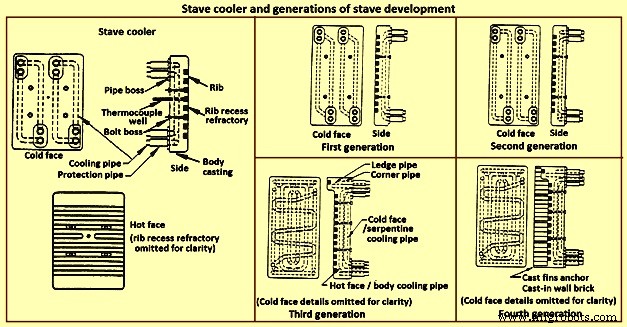
Fig 12 Stave cooler and generations of stave development
Staves are normally expected to retain a refractory lining in front for some time. After loss (expected) of the lining the staves are designed to resist the abrasive effects of descending burden and ascending dirty gas. As well, they are to absorb the expected process heat load and resist thermal load cycling and shock. Four generations of staves (Fig 12) are normally recognized in the industry.
First generation staves are no longer normally used. These staves have four cooling body circuits (with long radius bends which do not effectively cool the stave comers. These staves are made of gray iron castings with castable rib refractory. Second generation staves have four cooling body circuits with short radius bends for improved comer cooling. These staves are made of ductile iron castings with cast-in or glued-in rib bricks. Third generation staves have two-layer body cooling incorporating four or six cooling body circuits (stave hot face) and one or two serpentine cold face circuits (stave cold face) for additional or back-up cooling in the event of hot face circuit loss. These staves have additional edge cooling (top and bottom). The more frequent use of these staves is as cooled ledges to support a refractory lining. These staves have cast-in or mortared-in rib bricks. Fourth generation staves have two-layer cooling (similar to third generation). These staves have cooled ledges and cast-in wall brick lining eliminating the need for a manually placed interior brick lining.
Staves incorporating hot face ledges are more effective in retaining a brick lining than the smoother rib faced bricks. However, once the brick lining disappears, the ledges are very exposed within the furnace. The ledges disrupt burden descent and gas ascent. Exposed ledges tend to fail quickly. They are frequently serviced by cooling water separate from the main stave cooling circuit(s). In this way leaking ledge circuits can be more easily located or isolated. Some stave manufacturers are now providing separate ledge castings so that ledge cracking and loss does not damage the parent staves. As well, there is some present change in philosophy to abandon the application of ledges entirely.
Variations of the basic stave generation types are common. For example, staves of fourth generation type utilizing a refractory castable for the wall ling have been employed successfully. Alternatively, brick linings have been anchored to the stave bodies. Such approaches can be used to substitute for brick support ledges.
A ‘fifth’ generation of staves design has been the developed. It is the copper stave (Fig 13). The development of copper staves was carried out both in Japan and Germany for use in the region of bosh, belly, and lower stack to cope with high heat loads and large fluctuations of temperatures. While Japan has gone for cast copper staves, German copper staves are rolled copper plates having close outer tolerarnces and with drilling done for cooling passages. Drilled and plugged copper staves are typically designed for four water pipes in a straight line at the top and four water pipes in a stright line at the bottom. Materials for internal pipe coils include monel, copper, or steel. Unlike cast iron staves, copper staves are intended to be bonded to the cooling pipe.
The development of the cast-in copper stave has considered the following aspects. As per the first aspect, for the prevention of deformation, appropriate design of the stave length and bolt constrained points is important. The first aspect is that the use of the cast-in steel pipe copper stave with its own design is beneficial for effectively reducing the risk of deformation. Fig 13 shows the constrained points of a rolled copper stave and the cast-in steel pipe copper stave. A rolled copper stave is constrained to the shell by mounting bolts and pins. To prevent the weld at the base of a rising pipe from being damaged by stresses, rising piping is connected to the shell by an expansion joint. Due to this structure, the upper and lower ends of the staves are freely displaced, causing the staves to be easily deformed. The large thermal load which is repeatedly applied to the copper stave in the course of the fluctuation in the BF operations etc., causes plastic strain to be gradually accumulated, and results in large deformation. There are cases in which the deformation at the upper end has reached 50 mm or more and a weld has been broken, under the condition of an overly long stave, an in-appropriate bolt position, or high heat load exceeding the design condition.
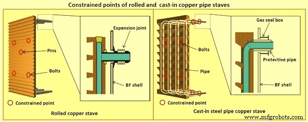
Fig 13 Constrained points of rolled and the cast-in pipe copper stave
Presently, the most popular type of copper stave is the rolled copper stave, the manufacturing process of which involves drilling holes on a copper plate. The water channel ends of these staves are plug-welded. The cast-in steel pipe copper stave, which has been developed, is made by casting bent steel pipes into the copper, a completely different manufacturing process from that of the conventional rolled copper stave. This unique manufacturing method has enabled achieving high energy efficiency and long life of BFs, which cannot be achieved using the rolled copper stave.
Natural evaporative stave cooling (NEVC) is a technique where boiler quality water is introduced into the bottom row of staves and flows by natural mean up the vertical cooling circuits. As the process heat conducts through the stave and cooling pipe into the water, the water in turn heats up. As the water warms, it expands. Since cooler water is being introduced below, the warm water tends to move upwards. At some point in the vertical cooling circuit, the water is at the boiling point. As the water changes its phase to steam, due to the latent heat of vapourization, additional heat is absorbed (driving the phase change). After boiling begins, two-phase flow (water and steam mixture) ascends the cooling pipes to the top of the furnace. Normally located on the furnace top platform are steam separator drums used to extract and vent the steam to atmosphere. Make-up water is introduced to the drum (to replace the discharged steam). The water is piped back by gravity to the furnace bottom and is fed once more to the staves. This cooling technique is very efficient and has low operating costs. There is no pumping equipment. The improvements in this system has been to boost the flow of the cooling water with recirculating pumps (forced evaporative cooling, FEVC) in order to ensure uniform cooling water flow and to cool the recirculating water (forced cold water cooling – FCWC). Both of these approaches have resulted in improved stave and lining life.
Staves provide an excellent protection for the shell plate throughout their service life (which is extended while the interior brick lining remains in place). Stave application has been implemented in all areas of the furnace from hearth wall up to and including the upper stack.
One drawback for conversion of an existing plate cooled furnace to stave cooling can be the cost of a new shell. However, if the existing shell is already in distress and is to be replaced in any event, the conversion cost is not a major factor.
Cast house
The cast house (Fig 14) is the area or areas at the BF where equipment is placed to safely extract the hot metal and liquid slag from the furnace, separate them, and direct them to the appropriate handling equipment or facilities. The hot metal and liquid slag are removed from the furnace through the tap hole. Only infrequently today slag is flushed from the slag notch. The equipment for tap hole is to be reliable and need minimum maintenance. Furnaces typically tap eight times to eleven times per day.
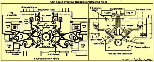
Fig 14 Cast house with four tap holes and two tap holes
Mud gun – The mud gun is used to close the tap hole after tapping is complete. A quantity of the tap hole mass is pushed by the mud gun to fill the worn hole and to maintain a quantity of the tap hole mass (the mushroom) within the hearth. The mud gun is normally held in place on the tap hole until the tap hole mass cures and the tap hole is securely plugged. A hydraulic mud gun uses hydraulic power to swing, hold, and push the tap hole mass. Typical injection pressure of tap hole mass is of the order of 20 MPa to 25 MPa, permitting it to push viscous mass into the furnace operating at high pressures. The hydraulic gun is held against the furnace with the equivalent of 15 tons to 35 tons of force. This type of mud gun can be swung into place in one motion.
An electro-mechanical gun has three separate electric drives for unit swing, barrel positioning, and ramming. Hence several separate motions are needed for accurate positioning of the mud gun at the tap hole. Tap hole mass injection pressure is in the range of only 5 MPa to 8 MPa. The electro-mechanical mud gun is latched to the furnace to keep it in place during plugging.
Tap hole drill – Tap hole drill is used to bore a hole though the tap hole clay into the hearth of the furnace. A drill unit is swung into place hydraulically and held hydraulically in the working position. A pneumatic motor feeds the hammer drill unit (with an attached drill rod and bit) into the hole. Compressed air is fed down the centre of the drill rod and the drill bit to cool the bit and blowout the removed tap hole mass. When the tap hole drill rod has penetrated into the hearth, the drill rod is retracted and the drill swings clear of the hot metal stream.
Soaking bar technique – The application of the soaking bar practice has improved the tapping process. When the tap hole mass is still pliable after plugging, a steel bar is driven into the tap hole by the tap hole drill. While the bar sits in place during the time between casts, it heats up by conduction from the hearth hot metal. This permits curing of the tap hole mass along its entire length (as opposed to curing with the furnace and setting at the outside near the furnace cooling elements). The cured tap hole mass is more resistant to erosion during tapping, hence improving tap flow rate control. Less tap hole mass is needed to replug the hole. When the tap hole is to be opened, a clamping device and a back hammering device on the tap hole drill extract the rod. The timing for tap hole opening can be more easily controlled (predicted) than by conventional drilling. This feature is important for smooth furnace operation and for scheduling of hot metal delivery to downstream facilities.
Same side tap hole equipment – Mud gun and drills have normally been installed on opposite sides of the tap hole. Design development has permitted installation of these equipments on one side of the tap hole. The drill swings over the mud gun or vice versa. This type of installation facilitates improved access for tap hole and trough maintenance and the improved application of trough and tap hole area flue collection.
With the advent of tuyere access platforms to facilitate tuyere and tuyere stock inspection and replacement, the headroom available for the tap hole equipment has diminished. However, same side tap hole equipment installations can be achieved with low headroom (for example 2.2 metres).
Trough and runner system – Typical hot metal and slag tapping rates are in the range of 4 to 6 tons per minute and 3 to 5 tons per minute, respectively. The trough and runner systems are to be designed to properly separate the iron and slag and to convey them away from the furnace for flow rates within the normal flow rate range and for unusual peak flow rates.
The hot metal trough (Fig 15) is a refractory lined tundish located in the cast house floor and designed to collect iron and slag after discharge from the furnace. The hot metal flows down the trough, under a skimmer and over a dam into the hot metal runner system. The hot metal level in the trough is dictated by the dam. Proper dam design submerges the lowest portion of the skimmer in the hot metal pool. The slag, being lighter than the hot metal, floats down the trough on top of the hot metal pool. Since it cannot sink into the hot metal and through the skimmer opening, it pools on top of the hot metal until sufficient volume collects to overflow a slag dam and run down the slag runner. At the end of the tapping, the slag runner dam height is lowered to drain off most of the slag. The residual hot metal is retained in the trough to prevent oxidation and thermal shock of the trough refractory lining.
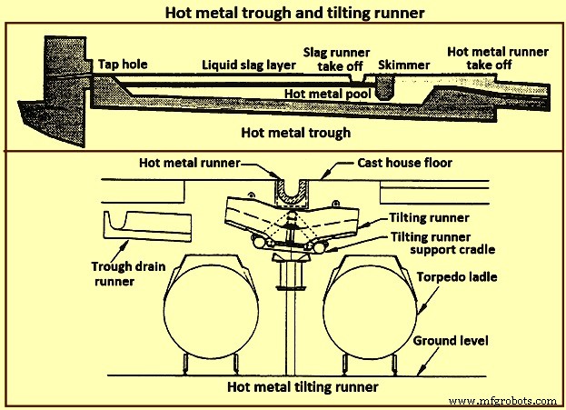
Fig 15 Hot metal trough and tilting runner
When maintenance of the trough lining is needed, the hot metal pool can be dumped by removing the hot metal dam, or by opening a trough drain gate, or by drilling into the side of the trough (at its lowest point) with a drain drill. The trough bottom is normally designed with a 2 % (minimum) slope for effective draining. Trough cross-section and length design are important for effective iron and slag flow pattern, retention, and separation. A good trough design results in hot metal yield improvements. Effective trough lining and cooling techniques are important for lining life, hot metal temperature, and cast house structural steel and concrete heat protection considerations. Troughs traditionally were contained in steel boxes ‘buried in sand’ in the cast house floor system. Improved trough design incorporates forced or natural air convection or water-cooling.
Cast house practice needs the runners to be as short as possible. This minimizes temperature loss of hot metal and reduces runner maintenance and flue generation. Shorter runners can also result in reduced capital expenditure for cast house building installation or modification. Since the runners are to slope away from the furnace, the cast house floor normally follows the same slope as the runners.
Slag runners are normally designed with a 7 % (minimum) slope. Slag can be directed to (i) slag pots for railway or mobile equipment haulage to a remote site for dumping, (ii) slag pits adjacent to the furnace for air cooling and water quenching prior to excavation by mobile equipment, and (iii) granulation facilities adjacent to the furnace for conversion of the liquid slag to granulated slag. Granulation units are provided with systems to eliminate flue emissions associated with environmental issues.
Hot metal runners are normally designed with a 3 % (minimum) slope. Hot metal is normally directed to hot metal transfer ladles (torpedo cars / open top ladles) for movement to the steel melting shop or pig casting machines. While normal practice used is to have one iron runner system with diverter gates directing the hot metal to different pouring positions, each with a ladle. Application of the tilting runner practice has been beneficial. A tilting runner is normally with an electrical motor-driven actuator (with a manual hand wheel back-up), and is tilted at around 5 degrees to divert the hot metal. A pool of hot metal is held in the tilting runner to minimize splashing and refractory wear. When one hot metal ladle has been filled, the runner is tilted to the opposite side to fill the other ladle. If needed, a locomotive removes the filled ladle and spots an empty ladle in its place. This operation can be done without plugging the furnace. When the tapping is finished, the tilting runner is tilted an additional 5 degrees to dump its pool of hot metal into the ladle.
Modern cast house design includes flat floors, where the runner is fully covered and is fitted flush with the floor. This allows safer and easier use of mobile vehicles in the cast house area. The use of radio controlled equipment and other devices have helped to reform cast house work, and these, along with effective emission control systems, have improved working conditions. As the BF hearth diameter is increased, there is a resulting need to increase the size of the cast-house. Large BF are normally designed with four tap holes (Fig 14). With a four top-hole configuration, the cast-house arrangement needs to provide sufficient space for movement around the floor itself. There is no design issues associated with this requirement as long as there is the necessary space provided in the site plan. Increasing the size of the cast-house in terms of floor plan does not represent a radical change in design philosophy which can pose a challenge the furnace designer. An efficient and strictly controlled tapping is necessary for ensuring a stable operation and high productivity of the BF.
Emission control
Fume collection requirements and applications appear to vary considerably around the globe. BFs presently have full, partial, or even no cast house fume collection system. Exhaust fan and bag house capacity of the order of 9,000 cubic meter per minute (cum/min) to 11,500 cum/min (depending upon operation and design practices) is typical for full flue capture of a two tap hole cast house installation (for trough runners and tilting runners).
Proper design and application of flue collection runner covers can facilitate cast house access (i.e. flat floor configuration using steel slabs or plates) for personnel and mobile equipment crossover. Runner covers can also reduce hot metal temperature loss and improve runner refractory longevity.
Some furnaces use flame suppression which eliminates the oxygen in the air directly over the trough and iron runners. Products of combustion prevent oxidation of the hot metal surface reducing visible particulate and flues.
Other aspects of BF design
It is necessary that complete study of every element in the process chain, from raw materials delivery to hot metal consumption is made to ensure that there are no ‘bottle necks’ in the system which can prevent the furnace from meeting the goals of its installation. While designing the BF, thought process is to be used to develop the furnace design and some alternatives are to be considered before freezing the design. During the designing of the furnace, those furnace equipments are to be selected which best meet the needs of the furnace operation.
The furnace design is to ensure (i) the furnace is capable of meeting the operational goals of production, productivity (tons per day per cubic metre of working volume), specific consumptions (kilograms per ton of hot metal), and product quality in cost effective manner, (ii) the furnace has the flexibility to accept and absorb the changes in the quality of the raw materials, and (iii) the furnace is capable of achieving the desired campaign life both with respect to time and the total production.
Financial justification is the over-riding consideration for the design. For this purpose, the economic study is to be very extensive. Further, the furnace design is to include latest technological developments so that the furnace does not become technologically outdated during its entire campaign.
The working volume of the furnace is the internal volume of the furnace calculated between the tuyeres and the stock line. Hearth productivity of the furnace is rated in tons per day per cubic metre of active hearth volume. Active hearth volume is the internal volume of the furnace calculated between the tuyeres and the tap hole. Active hearth volume is a measure of the holding capacity of the furnace for the liquids produced in the working volume (above the tuyeres). Hence, the tons per day per cubic metre of active hearth volume is a measure of the specific capacity (through-put per unit volume) of the hearth of the BF.
The design of the hearth is very important since it has a strong effect on the furnace operation. The furnace operation gets affected since the hearth liquid levels change rapidly which cause variations in gas flow pattern, gas utilization, and blast pressure. Also, because of these rapid changes in liquid level, there can be jamming / burning of the tuyeres which affect the blowing of the furnace.
The furnace hearth volume also determines the controls the operator is to exercise during furnace operation. For a very good hearth liquid level control, the high through-put furnace need around 90 % time spent in tapping. To make this time of tapping possible, cast floor is to be designed properly.
The furnace lining and cooling system needs special attention so that it does not pose any problem during the entire campaign of the BF. The selection of refractories, cooling elements, and internal furnace geometry is very important in this respect. Copper staves in this respect are expensive but they are very economical in comparison to the alternatives. Carbon lining of the hearth is very important for the long life of the hearth. The refractory lining thickness of the stack has implication on the furnace working volume.
The production needed normally determines the size of the BF. However, for the sizing of the BF, the raw materials, the product chemistry, and even operating philosophy are important. While the furnace size has implication on the capital cost, the productivity improvement has implication on the operating cost. The specific productivity of the furnace is to be determined for the determination of the size of the BF needed to produce the required quantity of hot metal. From the wide range of possible operating rates, the working volume of the furnace is to be calculated. Productivity and hence the furnace size is also to be based on the fuel rate. The fuel rate is dependent on the quality of raw materials, hot blast parameters, hot metal quality, and the operating philosophy.
The size is the most important factor for the determination of the BF productivity. However, there are other factors which also influence the BF productivity. The most important of these factors include (i) hot blast temperature and pressure, (ii) high top pressure, (iii) oxygen enrichment of the air blast, (iv) injection of auxiliary fuel at the tuyere, (v) prepared burden (sinter, pellets etc.), (vi) Fe content of the ferrous burden, (vii) ash in coke, (viii) quality of the coke, (ix) moisture content of the burden, (x) direct charging of fluxes (lime stone, dolomite etc.) in the BF, (xi) content of fines in the burden, (xii) quality of hot metal to be produced, (xiii) burden distribution control in the furnace, and (xiv) level of automation and control in the furnace.
The availability of furnace equipment, provision of stand-by equipment, and the maintenance philosophy are important factors which have high influence on the annual production from the BF. Further, incorporation of safe and healthy working practices during the operation of BF in the design of the BF is important which has a high influence on the furnace productions. In this regards, safety interlocks are to be provided at all the places where there exist a chance of unsafe operating practices to take place.
Productieproces
- Hoogovenslak en zijn rol in de werking van de oven
- Belangrijke aspecten van het ontwerp van hoogovens en bijbehorende hulpapparatuur
- Hoogovenprocesautomatisering, meet- en controlesysteem
- Opwekking en gebruik van hoogovengas
- Hoogovenproductiviteit en de beïnvloedende parameters
- Werking van hoogaluminiumoxideslakken en hoogovens
- Hoogoven koelsysteem
- Hoogoven Cast House en zijn werking
- Hoogoven en zijn ontwerp
- Operatiepraktijken en campagneleven van een hoogoven
- IJzerproductie door hoogoven en kooldioxide-emissies