


Opnames in continu gegoten staal en hun detectie
Inclusies in continu gegoten staal en hun detectie
Het continu gieten van staal is een belangrijk proces voor de productie van staal wereldwijd, vanwege de inherente voordelen van energiebesparing, hoog rendement, flexibiliteit in de werking en concurrerende kwaliteit van het gegoten product. Met de vestiging van continugieten als de belangrijkste route van staalproductie, komt de nadruk steeds meer te liggen op de kwaliteitsverbetering en kostenbesparende aspecten van de staalproductie door middel van continugiettechnologie. Een van de strengste kwaliteitseisen van vandaag is de reinheid van het staal. De hoge staalreinheid vereist strikte controle van niet-metalen insluitsels of gewoon insluitsels tijdens het continugietproces. Insluitingen die in het eindproduct achterblijven, kunnen de staaleigenschappen beschadigen en de kwaliteit aantasten.
Het verwijderen van insluitsels in de vorm van continugieten is moeilijk omdat het vloeibare staal vast wordt en insluitsels minder kans hebben om naar buiten te drijven. Het verwijderen van insluitsels en de uiteindelijke verdeling van insluitsels in het staalproduct zijn sterk afhankelijk van de eigenschappen van insluitsels, transport van insluitsels in het vloeibare staal en de interactie tussen insluitsels en stollende schil. Daarom is het begrip van de insluiting van insluitsels en hun uiteindelijke verdeling in het eindproduct belangrijk voor de controle van de reinheid en de kwaliteit van het staalproduct.
Het oppervlaktekwaliteitsprobleem van warm en/of koudgewalst staal is altijd een van de belangrijkste aandachtspunten, aangezien het rechtstreeks verband houdt met de staalkwaliteit en prijs. De oppervlaktekwaliteit van gewalst staal wordt ook beïnvloed door de werking van het continue giet- en opwarmproces, aangezien de insluitsels een van de belangrijkste oorzaken zijn van het ontstaan van oppervlaktescheuren in het gewalste staal. Er zijn pogingen gedaan om de kwaliteit van het staaloppervlak te verbeteren door de samenstelling en morfologie van de insluiting te wijzigen op basis van thermodynamische berekening. Maar deze pogingen lijken nog steeds niet voldoende te zijn om het probleem van de oppervlaktekwaliteit volledig op te lossen.
De evaluatie van insluitsels in staal is van groot belang en omvat (i) het onderzoeken van de totale hoeveelheid, morfologie, grootteverdeling en ruimtelijke verdeling van insluitsels, en (ii) het identificeren van hun chemische samenstelling.
De steeds toenemende vraag naar hoogwaardige staalproducten heeft het personeel van de staalproductie steeds meer bewust gemaakt van de eis van reinheid van het staal. Insluitingen zijn een belangrijk probleem in gietstaal, wat kan leiden tot overmatige reparatie of afkeuring ervan. Verschillende defecten in het gewalste staalproduct kunnen verband houden met de insluitsels. Het mechanische gedrag van het staal wordt voor een groot deel bepaald door de volumefractie, grootte, verdeling, samenstelling en morfologie van insluitsels en precipitaten die fungeren als stressverhogers. De verdeling van de insluitingsgrootte is bijzonder belangrijk, aangezien grote macro-insluitingen het schadelijkst zijn voor de mechanische eigenschappen. Soms wordt een catastrofaal defect veroorzaakt door slechts een enkele grote opname in een complete staalwarmte. Hoewel de grote insluitsels ver in de minderheid zijn door de kleine insluitsels, kan hun totale volumefractie groot zijn.
De ductiliteit wordt aanzienlijk verminderd door toenemende hoeveelheden oxide- of sulfide-insluitingen. Ook neemt de breuktaaiheid af wanneer insluitsels aanwezig zijn in gelegeerde staalsoorten met een hoge sterkte en een lagere ductiliteit. Vergelijkbare degradatie van eigenschappen door insluitingen wordt waargenomen in tests die langzame, snelle of cyclische vervormingssnelheden weerspiegelen, zoals kruip-, impact- en vermoeidheidstests. Verder veroorzaken insluitsels holtes, die scheuren kunnen veroorzaken. Grote exogene insluitsels kunnen problemen veroorzaken in de vorm van een inferieur oppervlak, slechte polijstbaarheid, verminderde weerstand tegen corrosie en in uitzonderlijke gevallen slaklijnen en lamineringen.
Inclusies verlagen ook de weerstand tegen 'hydrogen geïnduceerde scheuren' (HIC). De bron van de meeste vermoeiingsproblemen in staal zijn harde en brosse oxiden, vooral grote aluminiumoxide (Al2O3) deeltjes met een grootte van meer dan 30 micrometer. Hoewel de stollingsmorfologie van insluitsels belangrijk is in gietstaal, wordt de morfologie van insluitsels in gesmeed staalproducten grotendeels bepaald door hun mechanisch gedrag tijdens staalverwerking, d.w.z. of ze 'hard' of 'zacht' zijn ten opzichte van de staalmatrix. Het gedrag van verschillende soorten insluitsels met hun vervorming tijdens het rollen is schematisch weergegeven in figuur 1.
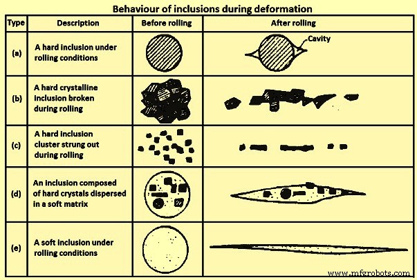
Fig 1 Gedrag van insluitsels tijdens vervorming
'Stringer'-vorming, type (b) en (c) in Fig 1, verhoogt de gerichtheid van mechanische eigenschappen, waardoor met name de taaiheid en ductiliteit nadelig worden beïnvloed. De slechtste insluitsels voor taaiheid en taaiheid, met name in de eigenschappen van platgewalste producten in de dikterichting, zijn die welke vervormen met de matrix, zoals (d) in figuur 1. Om deze problemen te vermijden, moeten de grootte en frequentie van schadelijke insluitsels worden aangepast. zorgvuldig gecontroleerd. Er mogen vooral geen insluitsels in het gietstaal aanwezig zijn boven een kritische maat.
Het karakteriseren van de insluitsels is een van de belangrijkste aspecten voor het verzekeren van schoon staal. Insluitsels zijn een type defect dat aanwezig is in staal en dat de eigenschappen zoals polijstbaarheid, ductiliteit en vermoeiingssterkte van het staal ernstig aantast. Daarom moeten insluitsels worden gecontroleerd voor de productie van hoogwaardig staal. Primaire insluitsels worden gevormd tijdens staalbehandelingen in de pollepel. De meeste hiervan worden afgevoerd naar de pollepelslak of op de voering. De rest van de insluitsels moet echter nog worden verwijderd via de opeenvolgende procesfasen en bovendien worden er nieuwe insluitsels gevormd tijdens het gieten en stollen.
Vanwege het afnemende aantal insluitsels bij toenemende grootte, leveren de verschillende grootte-intervallen verschillende problemen op. Met betrekking tot de polijstbaarheid is het grote aantal kleine insluitsels schadelijker dan de grote maar tegelijkertijd zeldzamere insluitsels, simpelweg omdat ze vaker voorkomen. Aan de andere kant, bij lage spanningsniveaus, zullen kritische scheuren, die kunnen leiden tot falen binnen de levensduur van een staalproduct, hoogstwaarschijnlijk groeien bij de zeer grote insluitsels. Deze insluitsels zijn zeldzaam en het is moeilijk om de dichtheid ervan correct in te schatten. Bij gemiddelde vermoeiingsspanningsniveaus concurreren insluitsels van gemiddelde grootte met oppervlaktedefecten als de scheurinitiatiepunten.
Insluitingen in staal kunnen endogeen (inheems) of exogeen ontstaan. Endogene insluitsels zijn het resultaat van legeringselementen in het staal die reageren met opgelost gas (zoals zuurstof) om vaste insluitsels in het gietstaal te vormen. De insluiting kan worden gevormd tijdens deoxidatie, heroxidatie of stolling door verminderde oplosbaarheid van gassoorten in de vaste toestand. Exogene insluitsels zijn afkomstig van bronnen buiten het vloeibare staal, zoals het meesleuren van slakken of vuurvaste schade.
Endogene inclusies
Endogene insluitsels zijn deoxidatieproducten of neergeslagen insluitsels tijdens het afkoelen en stollen van het staal.
Deoxidatieproducten – Alumina-insluitingen in staal met een laag koolstofgehalte met aluminium (LCAK) en silica (SiO2)-insluitingen in met silicium gedood staal, die worden gegenereerd door de reactie tussen de opgeloste zuurstof en de toegevoegde aluminium- en siliciumdeoxidanten, zijn typische deoxidatie-insluitingen. Aluminiumoxide-insluitingen zijn dendritisch wanneer ze worden gevormd in een omgeving met veel zuurstof. Cluster-type aluminiumoxide-insluitingen van deoxidatie of heroxidatie, zijn typisch voor met aluminium gedode staalsoorten. Alumina-insluitingen vormen gemakkelijk driedimensionale clusters door botsing en aggregatie vanwege hun hoge grensvlak-energie. Individuele insluitsels in het cluster kunnen een diameter hebben van 1 micrometer tot 5 micrometer. Vóór botsing, uiteenvallen of aggregatie met andere deeltjes kunnen ze de vorm hebben van een bloemplaat of (geaggregeerde) veelvlakkige insluitsels. Als alternatief wordt aangenomen dat koraalachtige aluminiumoxide-insluitingen het gevolg zijn van 'Ostwald-rijping' van oorspronkelijk dendritische of geclusterde aluminiumoxide-insluitingen. Silica-insluitingen zijn normaal bolvormig omdat ze in een vloeibare of glasachtige toestand in het vloeibare staal zijn. Silica kan ook agglomereren tot clusters.
Neergeslagen insluitsels – Deze insluitsels vormen zich tijdens het afkoelen en stollen van het staal. Tijdens het afkoelen wordt de concentratie opgeloste zuurstof/stikstof/zwavel in de vloeistof hoger terwijl de oplosbaarheid van die elementen afneemt. Zo slaan insluitsels zoals aluminiumoxide, silica, aluminiumnitride (AlN) en sulfide neer. Sulfiden vormen interdendritisch tijdens het stollen en kiemen vaak op oxiden die al in het vloeibare staal aanwezig zijn. Deze insluitsels zijn normaal gesproken klein (minder dan 10 micrometer groot).
Exogene insluitsels
Exogene insluitsels ontstaan voornamelijk door de incidentele chemische (reoxidatie) en mechanische interactie van vloeibaar staal met zijn omgeving (slakmeevoering en erosie van vuurvaste bekleding). Tijdens het machinaal bewerken produceren ze geratel, wat putjes en groeven veroorzaakt op het oppervlak van bewerkte secties, frequente breuken en overmatige gereedschapsslijtage.
Exogene insluitsels zijn altijd praktijkgerelateerd en hun grootte en chemische samenstelling leiden vaak tot de identificatie van hun bronnen, en hun bronnen zijn voornamelijk reoxidatie, meesleuren van slakken, voeringerosie en chemische reacties. Deze insluitsels hebben de volgende kenmerken.
Groot formaat – Exogene insluitsels van vuurvaste erosie zijn normaal gesproken groter dan die van meesleuren van slakken.
Samengestelde samenstelling / meerfasige aard – Exogene insluitsels worden veroorzaakt door de verschijnselen namelijk (i) als gevolg van de reactie tussen vloeibaar staal en silica, kunnen FeO en MnO in de slak en vuurvaste voering met de gegenereerde aluminiumoxide-insluitingen op hun oppervlak blijven, (ii) als exogene insluitsels bewegen vanwege hun grote omvang kunnen ze deoxidatie-insluitsels zoals aluminiumoxide op hun oppervlak vangen, (iii) exogene insluitsels fungeren als heterogene kernplaatsen voor precipitatie van nieuwe insluitsels tijdens hun beweging in vloeibaar staal, en (iv) slak- of reoxidatie-insluitsels kunnen reageren met de vuurvaste materialen van de voering of ander materiaal in het vloeibare staal losmaken.
Vorm – Exogene insluitsels hebben normaal gesproken een onregelmatige vorm, zo niet bolvormig door het meesleuren van slakken of het deoxidatieproduct silica. De bolvormige exogene insluitsels zijn normaal gesproken groot (groter dan 50 micrometer) en meestal meerfasig, maar de bolvormige deoxidatie-insluitsels zijn normaal gesproken klein en enkelfasig.
Aantal – Exogene insluitsels zijn klein in aantal vergeleken met kleine insluitsels.
Distributie – Exogene insluitsels hebben een sporadische verspreiding in het staal en zijn niet goed verspreid als kleine insluitsels. Omdat ze normaal gesproken vastzitten in staal tijdens het wemelen en stollen, is hun incidentie toevallig en sporadisch. Aan de andere kant drijven ze gemakkelijk naar buiten, dus concentreren ze zich alleen in gebieden van het staalprofiel die het snelst stollen of in zones waaruit hun ontsnapping door flotatie op de een of andere manier wordt belemmerd. Daarom worden deze insluitsels vaak aan de oppervlakte gevonden.
Effect op staaleigenschappen – Exogene insluitsels zijn schadelijker voor de staaleigenschappen dan kleine insluitsels vanwege hun grote omvang.
Een probleem dat de bron van de exogene insluitsels opheft, is de reden waarom zulke grote insluitsels niet snel naar buiten drijven als ze zich eenmaal in het staal bevinden. Mogelijke redenen kunnen zijn (i) late vorming tijdens staalproductie, overdracht of erosie in de metallurgische vaten, waardoor er onvoldoende tijd is om ze te rijzen voordat ze de gietvorm van de gietmachine binnengaan, (ii) onvoldoende oververhitting, (iii) vloeistofstroom tijdens stolling veroorzaakt insluiting van schimmelslakken, of (iv) opnieuw meevoeren van drijvende insluitsels voordat ze volledig in de slak terechtkomen.
Exogene insluitsels door reoxidatie – De meest voorkomende vorm van grote macro-insluitingen door reoxidatie in het staal is het aluminiumoxidecluster. Lucht is de meest voorkomende bron van heroxidatie, die kan optreden (i) vloeibaar staal in de verdeelbak vermengt zich met lucht van het bovenoppervlak aan het begin van het gieten vanwege de sterke turbulentie en de oxidefilms op het oppervlak van de stromende vloeistof worden gevouwen in de vloeistof, waarbij zwakke vlakken van oxidedeeltjes worden gevormd, (ii) lucht wordt in het vloeibare staal gezogen bij de verbindingen tussen de gietpan en de verdeelbak, en tussen de verdeelbak en de mal, en (iii) lucht dringt in het staal vanuit de bovenoppervlak van het staal in de pollepel, verdeelbak en mal tijdens het gieten.
Tijdens dit soort heroxidatie worden deoxiderende elementen, zoals aluminium, calcium en silicium enz. bij voorkeur geoxideerd en hun producten ontwikkelen zich tot de insluitsels, normaal gesproken één tot twee magnitudes groter dan deoxidatie-insluitsels. De oplossing om dit soort reoxidatie te voorkomen is om de blootstelling van lucht aan het gietproces te beperken. Dit kan worden gedaan (i) door een gordijn van inert gas te omhullen met behulp van een stalen ringverdeelstuk of een poreuze vuurvaste ring rond de verbindingen tussen de pollepel en de verdeelbak, en tussen de verdeelbak en de mal, (ii) door wat argongas in de trechter vóór het gieten, en in het oppervlak van de trechter tijdens het gieten, en (iii) door de argongasinjectie in de pollepel te regelen om oogvorming te voorkomen.
Een andere bron van heroxidatie bevindt zich in de slakken en vuurvaste bekledingen. Door dit reoxidatiemechanisme groeien insluitsels in het staal naarmate ze in de buurt van het slak- of voeringgrensvlak komen door de reactie SiO2 / FeO / MnO + [Al] =[Si] / [Fe] / [Mn] + Al2O3. Dit leidt tot grotere aluminiumoxide-insluitingen met variabele samenstelling. Dit fenomeen beïnvloedt exogene insluitsels verder op verschillende manieren, namelijk (i) deze reactie kan het oppervlak van de voering eroderen en ongelijkmatig maken, wat het vloeistofstroompatroon nabij de voeringwanden verandert en kan leiden tot een verder versneld uiteenvallen van de voering, en (ii) een grote exogene insluiting van gebroken voering of meegesleepte slak kan kleine insluitingen insluiten, zoals deoxidatieproducten, en ook fungeren als een heterogene kern voor nieuwe precipitaten, wat de samenstelling van exogene insluitsels bemoeilijkt.
Om heroxidatie van slakken en vuurvaste bekleding te voorkomen, is het erg belangrijk om een laag SiO2-, FeO- en MnO-gehalte te behouden. Er is gemeld dat bakstenen met een hoog alumina- of zirkonia-gehalte met een laag gehalte aan vrij silica geschikter zijn voor gebruik.
Exogene insluitsels door het meesleuren van slakken – Elke staalproductie of overdracht van vloeibaar staal omvat turbulente vermenging van slak en metaal, vooral tijdens overdracht tussen vaten. Hierdoor ontstaan slakdeeltjes die in het staal zweven. Slakinsluitingen, met een grootte van 10 micrometer tot 300 micrometer, bevatten grote hoeveelheden CaO (kalk) of MgO (magnesia), en zijn normaal gesproken vloeibaar bij de temperatuur van vloeibaar staal en zijn daarom bolvormig. Het gebruik van een 'H'-vormige verdeelbak en het gieten ervan door twee pollepels vermindert het meesleuren van slak tijdens de periode van het wisselen van de pollepel. De oorzaken die van invloed zijn op het meesleuren van slakken in het vloeibare staal tijdens het continugietproces omvatten (i) tijdens de overdrachtshandelingen van gietlepel naar verdeelbak en van verdeelbak naar gietvorm, speciaal voor open gieten, vortexen aan het bovenoppervlak van vloeibaar staal dat op het lage niveau van het vloeibare staal kan op verschillende manieren worden vermeden, zoals het afsluiten van het gieten voordat het vortexen begint, (ii) emulgering en meeslepen van slak aan het bovenoppervlak, vooral onder roeren van gas boven een kritische gasstroomsnelheid, (iii) turbulentie bij de meniscus in de mal, en (iv) slakeigenschappen zoals grensvlakspanning en slakviscositeit.
Als voorbeeld kan vormpoeder worden ingesloten in het vloeibare staal als gevolg van (i) turbulentie bij de meniscus (Fig 2A), (ii) vortexen (Fig 2C), (iii) emulgering veroorzaakt door bellen die van het staal naar de slak bewegen [Fig 2B en 2D), (iv) aanzuigen langs de mondstukwand als gevolg van drukverschil (2E), (v) stroming met hoge snelheid die slak van het oppervlak afschuift (2A), en (vi) niveauschommelingen (Fig 2B) .
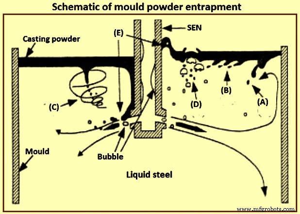
Fig 2 Schematische insluiting van schimmelpoeder
De grensvlakspanning tussen het staal en het vloeibare gietpoeder bepaalt de hoogte van de stalen meniscus en het gemak waarmee de flux kan worden meegevoerd. Specifiek levert een grensvlakspanning van 1,4 newton per meter (N/m) voor een kalk-silica-aluminiumoxideslak in contact met zuiver ijzer een meniscushoogte van ongeveer 8 mm op. De grensvlakspanning wordt tot een lage waarde verlaagd door oppervlakte-actieve stoffen zoals zwavel of door een grensvlakuitwisselingsreactie zoals de oxidatie van aluminium in staal door ijzeroxide in de slak. De zeer lage grensvlakspanning die gepaard gaat met een chemische reactie kan zorgen voor spontane turbulentie aan het grensvlak, via het Marangoni-effect. Dergelijke turbulentie kan een emulsie creëren op het grensvlak, waardoor ongewenste slakparels in het staal ontstaan.
Exogene insluitsels door erosie/corrosie van vuurvaste bekleding – Erosie van vuurvaste materialen, waaronder zand uit de put, los vuil, gebroken vuurvast metselwerk en keramische bekledingsdeeltjes, is een veel voorkomende bron van grote exogene insluitsels die typisch vast zijn en verband houden met de materialen van de pollepel en de verdeelbak zelf. Dit zijn normaal gesproken grote en onregelmatig gevormde materialen. Exogene insluitsels kunnen fungeren als plaatsen voor heterogene nucleatie van aluminiumoxide, of aggregaat met andere inheemse insluitsels. Het optreden van vuurvaste erosieproducten of mechanisch ingebrachte insluitsels kan de kwaliteit van anders zeer schoon staal volledig aantasten.
In sommige onderzoeken om het erosieproces te onderzoeken, is gemeld dat 'geglazuurde vuurvaste materialen' en de 'reactielagen aan het oppervlak van bakstenen' worden gevormd met vloeibaar staal bij 1.550 ° C tot 1600 ° C. De klompen met grote insluiting op de het oppervlak van de voering kan ook in het vloeibare staal worden losgelaten.
Voeringerosie treedt normaal gesproken op in gebieden met turbulente stroming, vooral in combinatie met reoxidatie, hoge giettemperaturen en chemische reacties. De parameters die de voeringerosie sterk beïnvloeden, worden hieronder beschreven.
Sommige staalsoorten zijn behoorlijk corrosief (zoals veel mangaan en soorten die nauwelijks worden gedood en een hoog gehalte aan oplosbare zuurstof hebben) en tasten voeringstenen aan.
Reoxidatiereacties, zoals die waarbij het opgeloste aluminium in het vloeibare staal silica in de vuurvaste bekleding vermindert, waardoor insluitsels op basis van ijzeroxide worden gegenereerd die zeer reactief zijn en de bekledingsmaterialen nat maken, wat leidt tot erosie van de vuurvaste bekleding in gebieden met hoge vloeistofturbulentie.
Baksteensamenstelling en -kwaliteit heeft een aanzienlijk effect op de staalkwaliteit. In een van de fabrieken zijn drie soorten materialen (hoog aluminiumoxide, Al2O3-SiC-C en MgO-C met een slijtagesnelheid van respectievelijk 1 mm / warmte, 0,34 mm / warmte, 0,16 mm / warmte) toegepast bij de slakkenlijn, waar het vuurvaste materiaal de neiging heeft te worden beschadigd door erosieve verdeelbakflux en slakken, en de MgO-C-steen vertoont de hoogste duurzaamheid van de drie. Mangaanoxide tast bij voorkeur de silicabevattende delen van het vuurvaste materiaal aan. Zeer zuivere aluminiumoxide- en zirkoniakorrels zijn bestand tegen aantasting door mangaanoxide.
Snelle vuurvaste erosie van staal met een hoog mangaangehalte kan worden beperkt door (i) het gebruik van vuurvaste materialen van aluminiumoxide of zirkonia met een zeer hoge zuiverheid, (ii) het minimaliseren van zuurstof door het staal volledig te doden met een sterk deoxidant zoals aluminium of calcium, en het voorkomen van luchtabsorptie. Op silica gebaseerde trechterbekledingen zijn slechter dan op magnesiumoxide gebaseerde gespoten bekledingen. Er wordt gesuggereerd dat vuurvaste materialen met een hoog aluminiumoxidegehalte de meest veelbelovende zijn. Het opnemen van calciumoxide in het vuurvaste mondstuk kan helpen door aluminiumoxide-insluitingen aan de wand vloeibaar te maken, zolang CaO-diffusie naar het grensvlak maar snel genoeg is en mondstukerosie geen probleem is. De erosie van de spuitmond kan worden tegengegaan door de vuurvaste samenstelling van de spuitmond te beheersen (bijvoorbeeld door natrium-, kalium- en siliciumverontreinigingen te vermijden), of door de spuitmondwanden te coaten met zuiver aluminiumoxide, boornitride of ander resistent materiaal. Het vuurvaste materiaal aan het oppervlak van de mantelwanden moet worden gekozen om reacties met het staal, die insluitsels en verstoppingen veroorzaken, tot een minimum te beperken.
Een te hoge snelheid van vloeibaar staal beïnvloedt de erosie van de bekleding langs de wanden in de verdeelbak, zoals de inlaatzone. Een pad kan worden gebruikt om erosie van de bodem van de verdeelbak te voorkomen en om het stromingspatroon te regelen. Er is gesuggereerd dat snelheden van vloeibaar staal van meer dan 1 meter per seconde gevaarlijk zijn met betrekking tot erosie.
Overmatige contact- of vultijd en hoge temperatuur verslechteren erosieproblemen. Tijdens een lange verblijfsperiode in de pollepel kunnen de grotere insluitsels in de pollepelslak drijven. Hoe langer het staal echter in contact is met de bekleding van de gietpan, hoe meer de neiging bestaat voor de producten van gieterosie. Oplossingen zijn gebaseerd op het ontwikkelen van zeer stabiele vuurvaste materialen voor een bepaalde staalsoort, het ontwikkelen van dichte slijtvaste vuurvaste inzetstukken voor gebieden met veel stroming en het voorkomen van heroxidatie.
Exogene insluitsels van chemische reacties - Chemische reacties produceren oxiden door inclusiemodificatie wanneer de calciumbehandeling niet correct wordt uitgevoerd. Het identificeren van de bron van deze insluitsels is niet altijd eenvoudig, omdat insluitsels die calciumoxide bevatten bijvoorbeeld ook afkomstig kunnen zijn van meegevoerde slakken.
Inclusie agglomeratie en verstopping – De agglomeratie van vaste insluitsels kan op elk oppervlak voorkomen, geholpen door oppervlaktespanningseffecten, ook op vuurvaste en bellenvormige oppervlakken. De hoge contacthoek van aluminiumoxide in vloeibaar staal (134 graden tot 146 graden) stimuleert een opname om zichzelf te hechten aan vuurvast materiaal om contact met staal te minimaliseren. Hoge temperaturen van 1.530 deg C maken sinteren van aluminiumoxide mogelijk. Grote contacthoek en grotere insluitingsgrootte bevorderen de agglomeratie van insluitsels. Door botsing en agglomeratie hebben insluitsels in staal de neiging om met toenemende tijd en temperatuur te groeien. Inclusiegroei door botsing, agglomeratie en coagulatie in ingots is het onderwerp geweest van verschillende onderzoeken, waarin de numerieke simulatie van inclusienucleatie, beginnend met toevoeging van deoxidant en groei door botsing en diffusie van nanogrootte tot microgrootte, wordt gerapporteerd. P>
De fundamenten van het sinteren van aluminiumoxide in clusters moeten verder worden onderzocht, hoewel sommige studies fractaltheorie hebben gebruikt om de clustermorfologie (functies) te beschrijven. Het meest voor de hand liggende voorbeeld van insluitingsagglomeratie op het oppervlak van vuurvaste bekledingen is verstopping van de spuitmonden tijdens het continu gieten van vloeibaar staal.
Effect van vloeistofstroom en stolling op insluitsels – Opnameverdeling bij continugieten van staal wordt beïnvloed door de vloeistofstroom, warmteoverdracht en stolling van het vloeibare staal. Een populaire index voor insluiting van insluiting is de kritische voortschrijdende snelheid van het stollingsfront, die wordt beïnvloed door verschillende parameters zoals insluitvorm, dichtheid, oppervlakte-energie, thermische geleidbaarheid, afkoelsnelheid (stollingssnelheid) en uitstekende omstandigheden van het stollingsfront. Er is gemeld dat beknelling wordt gecontroleerd door weerstand en grensvlakkrachten (Van der Waals-kracht). Er is gesuggereerd dat hoe sneller de stollingssnelheid is, hoe groter de kans op beknelling is. De kans op beknelling neemt af met toenemende stollingstijd, minder segregatie, kleinere uitsteeksels aan het stollingsfront. De dendrietarmafstanden hebben een groot effect op het insluiten van insluitsels en zijn gerelateerd aan de verschijnselen van duwen, verzwelgen; of beknelling.
Continue gietbewerkingen, insluitsels en schoon staal
Door continu gieten wordt de reinheid van het staal gecontroleerd. Een systematische studie van het verwijderen van insluitsels heeft uitgewezen dat behandeling met een pollepel de insluitsels met ongeveer 65% tot 75% verlaagt, de verdeelbak de insluitsels verwijdert met ongeveer 20% tot 25%, hoewel soms reoxidatie heeft plaatsgevonden, en de schimmel verwijdert insluitsels met ongeveer 5% tot 10%. Tundish-bewerking heeft een groot effect op de reinheid van het staal. De belangrijke factoren bij trechterbewerkingen die van invloed zijn op de reinheid van staal, zijn trechterdiepte en -capaciteit, gietovergangen, trechterbekleding vuurvast materiaal, trechterstroom, argongas roeren en trechterstroomregeling.
Topslakken – De bovenste slakken in de pollepel en verdeelbak hebben verschillende functies, zoals (i) isolatie van het vloeibare staal, zowel thermisch (om overmatig warmteverlies te voorkomen) als chemisch (om luchtinsluiting en heroxidatie te voorkomen), en (ii) absorptie van de insluitsels om extra staalraffinage te bieden. Een veel voorkomende trechterstroom is verbrande rijstschil, die goedkoop is, een goede isolator en een goede dekking biedt zonder korstvorming. Rijstkaf bevat echter veel silica (ongeveer 80% SiO2), dat kan worden gereduceerd om een bron van insluitsels te vormen. Ze zijn ook erg stoffig en kunnen met hun hoge koolstofgehalte (ongeveer 10 % C) verontreiniging van ultralaag koolstofstaal veroorzaken.
Basische fluxen (op basis van CaO-Al2O3-SiO2 en silica minder dan 10%) zijn theoretisch veel beter dan rijstschil tijdens het raffineren van LCAK-staal, en zijn gecorreleerd met minder zuurstof in de verdeelbak. In een onderzoek is de totale zuurstof bijvoorbeeld afgenomen van 25 ppm (parts per million) en 50 ppm tot 19 ppm en 35 ppm, waarbij de basiciteit van de flux toenam van 0,83 tot 11. In een van de de staalfabriek, het gebruik van basische fluxen, het totale zuurstofgehalte in de mal is naar verluidt lager en het defect aan het staalproduct is afgenomen. Het is echter waarschijnlijker dat de basisflux niet effectief is, omdat deze gemakkelijk een korst vormt aan het oppervlak, vanwege de snellere smeltsnelheid en de hoge kristallisatietemperatuur. Deze korst resulteert in de ontwikkeling van een open, slakvrij oog rond de mantel van de pollepel tijdens het vollopen, wat niet alleen een buitensporig gebied biedt voor reoxidatie, maar ook een aanzienlijk warmteverlies door straling en ongemak veroorzaakt voor de operators op het werkplatform. Ook hebben basische fluxen normaal gesproken een lagere viscositeit. Daarom worden ze gemakkelijker meegesleept. Om deze problemen te voorkomen, heeft één staalfabriek een tweelaags vloeimiddel gebruikt, met een basisvloeimiddel met laag smeltpunt op de bodem om de insluitsels te absorberen, en een bovenlaag van vloeimiddel op basis van rijstkaf om isolatie te bieden. Hierdoor is het totale zuurstofgehalte verlaagd van 22,5 ppm naar 16,5 ppm.
Tundish-apparatuur voor diepte, capaciteit en stroomregeling – Het trechterstroompatroon moet worden ontworpen om de verblijftijd van vloeibaar staal te verlengen, 'kortsluiting' te voorkomen en de verwijdering van insluitingen te bevorderen. De trechterstroom wordt geregeld door de geometrie, het niveau, het ontwerp van de inlaat (omhulsel) en stroomregelingsapparatuur zoals impactpads, stuwen, dammen, schotten en filters. Diepe verdeelbak met een grote capaciteit verhoogt de verblijftijd van vloeibaar staal en deeltjes en bevordert zo de verwijdering van insluitingen. Diepe verdeelbak ontmoedigt ook de vorming van wervelingen, waardoor er meer tijd is voor het overschakelen van de gietlepel voordat het meesleuren van slakken een probleem wordt. De afmetingen van de verdeelbak voor LCAK-staal zijn de afgelopen 20 jaar wereldwijd geleidelijk toegenomen, en bereikten doorgaans 60 tot 80 ton met een diepte van ongeveer 1,8 meter inch in het geval van een continugietmachine voor plakken.
Indien goed uitgelijnd, en misschien samen met stuw(en) en dam(men), kan een gietkussen de reinheid van het staal verbeteren, vooral tijdens het verwisselen van pollepels. Als voorbeeld, het toevoegen van het gietkussen bij een van de staalfabrieken heeft het aluminiumoxide tijdens de gietlepelovergangen verlaagd van 48 ppm naar 15 ppm. In een andere staalfabriek is de totale hoeveelheid zuurstof gedaald van 26 ppm (met een bolvormige pad) naar 22 ppm (met een wieldoppad). Bij weer een andere staalfabriek is de staalreinheid verbeterd door 77 gaten in hun dam te maken, waardoor deze als een gedeeltelijk filter fungeert. Bij een andere staalfabriek heeft een vergelijkbare techniek, bestaande uit keerschotten gecombineerd met een aanvankelijke verdeelbakafdekking, de gemiddelde totale zuurstof in de verdeelbak tijdens stationair gieten verlaagd van 39 +/- 8 ppm tot 24 +/- 5 ppm.
Keramische filters en CaO-filter zijn zeer effectief in het verwijderen van insluitsels. Hun kosten en effectieve bedrijfstijd vóór verstopping maken het gebruik ervan normaal gesproken echter onbetaalbaar. Het injecteren van inert gas in de verdeelbak vanaf de bodem verbetert de menging van het vloeibare staal en bevordert de botsing en verwijdering van insluitsels. Bij een van de staalfabrieken is door toepassing van deze technologie het totale zuurstofgehalte in de verdeelbak met succes verlaagd tot 16 ppm. Het gevaar van deze technologie is echter dat alle met insluitsels beladen bellen die uit de verdeelbak ontsnappen en vast komen te zitten in de streng, ernstige defecten veroorzaken. Er is gemeld dat de oxide-oppervlaktefractie (0,001%) van staal in verdeelbak met 25% afneemt door deze techniek in vergelijking met die zonder deze techniek.
Overgangen casten – Gietovergangen vinden plaats aan het begin van een gietvolgorde, tijdens het verwisselen van pollepels en mondstukwisselingen en aan het einde van het gieten. Deze overgangen zijn verantwoordelijk voor het merendeel van de reinheidsgebreken. Insluitingen worden vaak gegenereerd tijdens overgangen en kunnen lang aanhouden, waardoor veel staal wordt verontreinigd. De splinterdefectindex aan het begin van de eerste heat bleek 5 keer hoger te zijn dan die in het midden van de eerste heat en meer dan 15 keer die van opeenvolgende heats. Tijdens deze onstabiele gietperiodes is de kans groter dat slak wordt meegevoerd en lucht wordt geabsorbeerd, wat reoxidatieproblemen veroorzaakt. Een ‘zelfopenende’ pollepel gaat vanzelf open zonder de spuitmond te hoeven doorboren. Bij het prikken moet de lijkwade worden verwijderd en hierdoor kan reoxidatie plaatsvinden, vooral tijdens de eerste 650 mm tot 1.200 mm van het gieten. Door lans geopende heats hebben totale zuurstofniveaus die ongeveer 10 ppm hoger zijn dan de zelf-geopende heats. Zorgvuldige verpakking van het zand van de pollepelopening helpt bij het zelfopenen van de pollepel. Pollepelzand is ook een bron van heroxidatie vanwege het hoge silicagehalte.
Een verbetering tijdens het overstappen op de pollepel is om de vloeistofstroom in de mal te stoppen totdat de verdeelbak gevuld is en om gas door de stop te laten borrelen om de flotatie van de insluiting te bevorderen. Een andere verbetering is het openen van nieuwe pollepels met ondergedompelde omhulling. With this measure, total oxygen has decreased at one of the steel plant from 41 +/- 14 ppm to 31 +/- 16 ppm with more consistent quality throughout the sequence.
As an example, at one of the steel plant, total oxygen in tundish during transitions is 50 ppm to 70 ppm, compared with only 25 ppm to 50 ppm at steady state. At other steel plants, the difference is only 3 ppm. One of the steel plants has reported transitions to have total oxygen only 19.2 ppm relative to 16 ppm at steady state while another steel plant has reported total oxygen of 27 +/- 5 ppm during transitions and 24 +/- 5 ppm during steady casting. At one other steel plant, the nitrogen pickup in tundish is 5 ppm to 12 ppm during the start period of the teeming which decreases to 0 ppm to 2 ppm after around 12 minute of teeming (steady casting state).
Near the end of the teeming of a ladle, ladle slag can enter the tundish, due to the vortex formed in the liquid steel near the ladle exit. This phenomenon needs some steel to be kept in the ladle upon closing (e.g. a four ton of ‘heel’). In addition, the tundish depth drops after ladle close, which disrupts normal tundish flow and can produce slag vortexing, slag entrainment, and increased total oxygen in the mould.
Shrouding, argon protection, and sealing – Steel shrouding from ladle to the mould includes ladle slide gate shrouding, ladle collector nozzle, ladle shroud connection, tundish well block, and top plate of the tundish slide gate. Shroud design variations are of great importance in the operations of the tundish-to-mould transfer of liquid steel. Use of an optimized shrouding system greatly lowers reoxidation during transfer operations. For example, use of a ladle shroud has lowered nitrogen pickup from 24 ppm to 3 ppm relative to open pouring at one of the steel plant. In another steel plant, replacing the tundish pour box with a ladle shroud and dams has lowered nitrogen pickup (ladle to tundish) from 7.5 ppm to 4 ppm, and also has lowered slag entrainment during transitions. At one other steel plant, improving the shroud system from ladle to tundish has lowered the nitrogen pickup from 14 ppm to 3 ppm.
Shrouding the ladle to tundish stream at one of the steel plants has lowered the dissolved aluminum loss from 130 ppm to 70 ppm and has lowered the total oxygen increase by 12 ppm. When pouring without shrouds, which is common in billet casting, the turbulence of the casting stream is very important. A smooth stream entrains much less oxygen than a turbulent or ‘ropy’ stream. For the production of a smooth stream between the tundish and the mould in these operations, the metering nozzle edges are to be maintained and high speed flow in the tundish across the nozzles is to be avoided. A protective tundish cover with carefully sealed edges also helps in lowering total oxygen from 41.5 ppm to 38 ppm.
A variety of inert gas shrouding systems is now available. Total oxygen in the cast product (LCAK steel) can be lowered from 48.5 ppm to 28.5 ppm by shrouding between the ladle and the tundish, and to 23 ppm by this shrouding plus argon sealing. It is very important to carefully seal the joints in the shrouds, both to improve cleanliness and to prevent clogging. Improving the bayonet system between the ladle nozzle and ladle shroud, lowers the nitrogen pickup there from 8 ppm to less than 1 ppm. Stiffening the submerged entry nozzle (SEN) holder and increasing its maintenance has lowered the initial nitrogen pickup from 1.8 ppm to 0.3 ppm in one of the steel plants.
Inert gas can protect the steel from air reoxidation in several ways. To combat air entrainment at the beginning of a cast, the tundish can be purged with inert gas (to displace the air) prior to ladle opening, which lowers both the total oxygen and the nitrogen pickup during startup. Argon injection to pressurize the shrouds can help to prevent the liquid steel from air reoxidation through any joints or leaks. Guidelines for minimum argon gas flow to ensure positive pressure inside the nozzle are to be made. In addition, flooding the joints with argon gas ensures that any leaks aspirate inert gas and not air.
Injecting argon into the tundish stopper rod and improved sealing at one steel plant has decreased nitrogen pickup from tundish to cast product from 5 ppm to 1.8 ppm, has lowered total oxygen in the cast product from 31 ppm to 22 ppm, has decreased the size of alumina clusters in the cast product, and has decreased clogging. Elsewhere, argon injection through the stopper rod lowered the number of inclusions detected by the Mannesmann inclusion detection by analysis surfboards (MIDAS) method by 25 % to 80 %. Injection of argon gas purge through upper plate of the sliding gate has lowered the quantity of 50 micrometers to 100 micrometers sized inclusions from 3 per square centimeter to 0.6 per square centimeter, and lowered 100 micrometers to 200 micrometers macro-inclusions from 1.4 per square centimeter to 0.4 per square centimeter.
Clogging and new techniques at SEN – The nozzle is one of the few control parameters which is relatively inexpensive to change, yet has a profound influence on the flow pattern and hence on the quality of the cast product. Nozzle parameters include bore size, port angle and opening size, nozzle wall thickness, port shape (round, square, or oval), number of ports (bifurcated or multiport), nozzle bottom design (well, flat , or sloped), and submergence depth. Both too large and too small submergence depth increases problems with longitudinal cracks and transverse depressions.
One of the studies has found the occurrence of corundum (Al2O3) covering the bore surface of nozzles used to pour aluminum killed steel ingot early in 1949. Another study has found that nozzle blockage occurred with high levels aluminum (0.0036 %) and that nozzle sectioning revealed dendritic growth of alumina from the nozzle wall onto the bore. Yet another study has observed clogs of aluminum, zircon, titanium, and the rare earths.
Nozzle clogs are caused by reoxidation, or by the accumulation of solid oxides or sulphides, such as alumina and calcium sulphide (CaS) in the steel. In addition to interfering with the production process, tundish nozzle / SEN clogging is detrimental to steel cleanliness for several reasons such as (i) dislodged clogs either become trapped in the steel, or they change the flux composition, leading to defects in either case, (ii) clogs change the nozzle flow pattern and jet characteristics leaving the nozzle, which disrupt flow in the mould, leading to slag entrainment and surface defects, and (iii) clogging interferes with mould level control, as the flow control device (stopper rod or slide gate) tries to compensate for the clog.
The cure for the nozzle clog problem includes improving steel cleanliness by improving ladle practices, implementing smooth and non-reacting refractories, and controlling fluid flow though the nozzle for ensuring a smooth flow pattern. Changing from a three-plate slide gate system to a stopper rod system has reduced clogging at one of the steel plant. Several practices can be used to minimize clogging. In addition to taking general measures to minimize inclusions, clogging through refractory erosion can be countered by controlling nozzle refractory composition, (e.g. avoiding sodium, potassium, and silicon impurities), or coating the nozzle walls with pure alumina, boron nitride, or other resistant material. There are several new techniques at SEN which have reported to improve the fluid flow pattern and inclusion removal, such as (i) swirl-nozzle technique, (ii) step nozzle technique, (iii) multi-ports nozzle, and (iv) oval offset bore throttle plate.
Swirl-nozzle technique – A fixed blade placed at the upstream end of the SEN induces a swirl flow in nozzle. Centrifugal force generated by the swirling flow in the nozzle can distribute the liquid steel equally to its two spouts. Since liquid steel stream with centrifugal force has the maximum velocity in the vicinity of the wall inside the nozzle, it tends to flow out of the upper part of the spout. Hence, the velocity distribution which tends to have higher values toward the lower part of the spout with a conventional nozzle can become uniform. It has been reported that by using this swirl nozzle for the continuous casting, the defect ratio of finish products (coils) has decreases to 25 % of the conventional nozzles, and casting speed has riseby 30 %. Its cost is higher only by 20 % than the cost of the conventional and hence it is cheaper than using an ‘electro-magnetic brake’. This swirl flow pattern can also be generated by the ‘electro-magnetic stirring’ at the nozzle, which can also improve the solidification structure of the cast steel as well.
Step nozzle – The flow pattern at out-ports of conventional SEN is uneven or biased because of the sliding gate of SEN. This biased flow pattern (swirl flow at out-ports of SEN) increases the impingement of the jet, and hence worsens inclusion removal to top surface. By using inner annular steps, the biased flow in mould can be weakened. The calculation suggests that the removal fraction of 50 micrometers inclusions to the top surface of the mould is 2 % with the conventional SEN, but increases to 7 % with the use of the stepped SEN.
Oval offset bore throttle plate – In the conventional system, gate throttling results in a highly skewed and biased flow in the tundish-to-mould flow channel both upstream and downstream of the gate. These effects have considerably diminished the offset bore system. The offset gate design extracts the fluid more centrally from the tundish well nozzle. Hence, the system is less sensitive to any build-up on the walls of the well nozzle, which extends the useful life of the tundish well nozzle and hence, allowing longer tundish sequences. In practice, it has also been found that clogging within the plates of the offset bore gate is considerably reduced as compared to the conventional gate.
Multiple out-ports – It is well known that the surface velocity of the mould has a big effect on slag entrainment and top surface fluctuation. Several defects are related to the surface velocity of the mould. Thus decreasing the surface velocity is very important to improve the steel cleanliness. This task can be targeted by using multiple out-ports at SEN. Addition of a bottom hole at SEN lowers the momentum of the side jets so it is possible to get a good steel flow and meniscus condition even under high throughput which is better stabilized.
Mould and operation of continuous casting machine
The continuous casting mould region is the last refining step where inclusions either are safely removed into the top slag layer or they become entrapped into the solidifying shell to form permanent defects in the steel product. Mcpherson has used the words ‘mould metallurgy’ in 1985 to emphasize the importance of the mould to improve steel cleanliness. The mould flow pattern is very important for avoiding defects since it affects particle transport and removal to the top slag or entrapment by the solidifying shell.
Top surface control – Directing too much flow towards the top surface generates surface defects, due to transients, turbulence at the meniscus, and inclusion problems from slag entrainment. However, decreasing surface flows too much can also generate problems. These include surface defects due to the meniscus region becoming too stagnant, and a higher fraction of incoming inclusion particles being sent deep before they can be removed into the slag. Hence, a balance is to be found in order to optimize the flow parameters to avoid defects.
The most obvious source of surface defects is the capture of foreign particles into the solidifying shell at the meniscus. If the steel jet is directed too deep or has too little superheat, then the liquid surface has very little motion and becomes too cold. This can lead to freezing of the steel meniscus, which aggravates the formation of meniscus hooks. This allows inclusions and bubbles to be captured, the latter forming pinholes just beneath the surface of the cast product. As an example, decreasing surface velocity below 0.4 metre/second (m/s) has been measured to increase surface pinhole defects. For avoiding these problems, the flow pattern is to be designed to exceed a critical minimum velocity across the top surface, which is estimated to be around 0.1 m/s to 0.2 m/s.
Slag entrainment is less likely with deeper nozzle submergence and slower casting speed. For avoiding shearing slag in this manner, the surface velocity is to be kept below a critical value. This critical velocity has been measured in water – oil models as a function of viscosity and other parameters. Entrainment is more difficult for shallower slag layers, higher slag viscosity, and higher slag surface tension.
A maximum limit of the argon gas injection flow rate into the nozzle has been reported as a function of the casting speed, beyond which mould slag entrainment takes place. Increasing casting speed tends to increase transient turbulent fluctuations, and worsens the extent of flow pattern asymmetries. This in turn worsens detrimental surface turbulence and level fluctuations. Improving internal cleanliness frequently needs limiting the maximum casting speed, to avoid pencil pipe defects. Lower casting speed and avoiding variations in casting speed both reduce the rate of slivers. More precisely, it is important to lower the liquid mass flow rate in order to control the jet velocity leaving the nozzle.
Fluid flow pattern – The mould flow pattern is controlled by adjustable parameters such as nozzle geometry nozzle submergence depth, argon gas injection rate, and the application of electro-magnetic forces. It also depends on parameters which normally cannot be adjusted to accommodate the flow pattern, such as the position of the flow control device (slide gate or stopper rod), nozzle clogging, casting speed, strand width, and strand thickness. All of these parameters together form a system which is to be designed to produce an optimal flow pattern for a given operation.
Bubbles, which are injected into the nozzle and the mould, have five effects related to the control of tge steel quality. These effects are (i) helping to reduce nozzle clogging, (ii) helping influence and control the flow pattern in the mould, (iii) generating serious top surface fluctuation even emulsification if gas flow rate is too large, (iv) capturing inclusions as they flow in the liquid steel, and (v) bubbles entrapped solid oxide particles captured by solidified shell eventually lead to surface slivers or internal defects.
Normally, low gas flow tends to double-roll flow pattern, while a high argon flow rate induces single-roll flow. This phenomenon has been studied as early as in 1983. For maintaining a stable double roll flow pattern, which is frequently optimal, the argon is to be kept safely below a critical level. Excessive argon injection can generate transient variation of the jets entering the mould, introduce asymmetry in the mould cavity, and increase surface turbulence. Argon gas bubbles can also be trapped in the solidifying steel shell to form blister defects, such as pencil pipe in the finish product.
It has been observed that inclusion entrapment varies from side to side, which suggests a link with the variations in the transient flow structure of the lower recirculation zone, and the asymmetrical flow pattern (Fig 3), which can be induced by nozzle clogging, by turbulence, and by excessive argon gas injection. It is especially important to keep nearly constant the liquid steel level in the mould, powder feeding rate, casting speed, gas injection rate, slide gate opening, and nozzle position (alignment and submergence).
Electro-magnetic forces can be applied to the liquid steel in a number of ways to alter considerably the flow pattern in the strand. It has been reported that electro-magnetic stirring of outer strands can improve the steel cleanliness, lowering total oxygen in the cast product from 30 ppm to 20 ppm. Another example is the electro-magnetic brake (EMBR), which bends the jet and shortens its impingement depth, to lessen the likelihood of capture by the solidified shell deep in the strand.
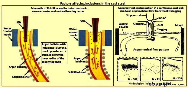
Fig 3 Factors affecting inclusions in cast steel
Casting machine curvature – Continuous casting machines with curved mould are known to entrap more particles than straight (vertical) mould casting machines (Fig 3), since the particles gradually move upwards towards the inside radius while they spiral with the liquid in the lower recirculation zone. Majority of the particles are captured 1 m to 3 m below the meniscus, independent of casting speed, which corresponds to a specific distance through the strand thickness. Frequently, inclusions concentrate at surface and one-eighth to one-fourth of the thickness from the top of the inside radius surface. The vertical bending casting machine has fewer inclusions and pinholes, which are distributed deeper, relative to the curved casting machine. Particle entrapment defects such as pencil pipe can be lessened if at least the top 2.5 m section of the casting machine is straight (vertical).
Inclusions detection methods
The quantity, size distribution, shape and composition of inclusions are required to be measured at all stages of the production of steel. Measurement techniques range from direct methods, which are accurate but costly, to indirect methods, which are fast and inexpensive, but are only reliable as relative indicators. The inclusion detection methods are sometimes divided into two categories namely (i) off-line methods, and (ii) online methods.
Direct methods
There are several direct methods to evaluate steel cleanliness. These methods are described below.
Inclusion evaluation of solid steel sections
Several traditional methods directly evaluate inclusions in a two dimensional section through solidified product samples. The last five of the methods described below add the ability to measure the composition of the inclusions.
Metallographic microscope observation (MMO) – MMO method can only reveal the two-dimensional section of an inclusion though the inclusions are three-dimensional in nature.
Image analysis (IA) – This enhancement to MMO improves on eye evaluation by using high speed computer evaluation of video-scanned microscope images to distinguish dark and light regions based on a grey scale cutoff.
Sulphur print – It is a popular and inexpensive macro-graphic method which distinguishes macro-inclusions and cracks by etching sulphur rich areas. It has the same issues as the other two-dimensional methods.
Scanning electron microscopy (SEM) – This method clearly reveals the three-dimensional morphology and the composition of each inclusion. Composition can also be measured with ‘electron probe micro analyzer’ (EPMA).However, extensive sample preparation is needed to find and expose the inclusion(s).
Optical emission spectrometry with pulse discrimination analysis (OES-PDA) – The optical emission spectrometry (OES) method analyzes elements dissolved in liquid steel. Inclusions cause high intensity spark peaks (relative to the background signal from the dissolved elements), which are counted to give the PDA (pulse discrimination analysis) index.
Laser micro-probe mass spectrometry (LAMMS) – In this method, individual particles are irradiated by a pulsed laser beam, and the lowest laser intensity above a threshold value of ionization is selected for its characteristic spectrum patterns due to their chemical states. Peaks in LAMMS spectra are associated with elements, based on comparison with reference sample results.
X-ray photoelectron spectroscopy (XPS) – This method use x-rays to map the chemical state of individual inclusions which greater than 10 micrometers in size.
Auger electron spectroscopy (AES) – This method use electron beams to map the composition of small areas near the surface of flat samples.
Cathodoluminescence microscope – Under microscope, the steel or lining sample section is stimulated by a cathode-ray (energetic electron-beam), to induce cathodoluminescence (CL). The colour of CL depends on the metal ions type, electric field, and stress, allowing inclusions to be detected.
Inclusion evaluation three-dimensional steel matrix
Several methods directly measure inclusions in the three-dimensional steel matrix. The first four of these scan through the sample with ultrasound or x-rays. The last four of these volumetric methods first separate the inclusions from the steel.
Conventional ultrasonic scanning (CUS ) – In this method, the transducer (typically a piezoelectric) emits a sound pressure wave which is transferred into the sample with the aid of a coupling gel. The sound waves propagate through the sample, reflect off at the back wall and return to the transducer. The magnitude of the initial input pulse and the reflected signals are compared on an oscilloscope to indicate the internal quality of the sample. Obstructing objects in the path of the sound scatters the wave energy. This non-destructive method detects and counts inclusions larger than 20 micrometers in the solidified steel samples.
Mannesmann inclusion detection by analysis surfboards (MIDAS) – In MIDAS method the steel samples are first rolled to remove the porosity and then ultrasonically scanned to detect both the solid inclusions and compound solid inclusions / gas pores. This method has been now renamed as the ‘liquid sampling hot processing’ (LSHP) method.
Scanning acoustic Microscope (SAM) – In this method, a cone-shaped volume of continuous cast product is scanned with a spiraling detector, such as a solid ultrasonic system, which automatically detects inclusions at every location in the area of the sample surface, including from surface to centre-line of the product.
X-ray detection – By this method, inclusions images are detected by their causing variation in the attenuation of x-rays transmitted through the solid steel. An inclusion distribution can be constructed by dividing a sample into several wafers and subjecting each to conventional x-rays to print penetrameter radiograghs for image analysis.
Chemical dissolution (CD) – In the CD method, acid is used to dissolve the steel and partially extract the inclusions. The inclusion morphology and composition can be detected by another method like SEM, or be fully extracted by dissolving the complete steel sample. The three dimensional nature of inclusions can be revealed by this method. The disadvantage is that the acid dissolves away FeO, MnO, CaO, and MgO in the inclusions. Hence, this method is good to detect only alumina and silica inclusions.
Slime (electrolysis) technique – This method is also called ‘potentiostatic dissolution technique’. A relatively large (200 grams to 2 kilograms) steel sample is dissolved by applying electric current through the steel sample immersed in a ferrous chloride or ferrous sulphate solution. This method is used to reveal the individual, intact inclusions. One disadvantage of this method is the cluster inclusions possibly break into separate particles after extraction from steel.
Electron beam (EB) melting – In this method, a sample of aluminum killed steel is melted by an electron beam under vacuum. Inclusions float to the upper surface and form a raft on top of the liquid sample. The normal EB index is the specific area of the inclusion raft. An enhanced method (EB-EV – ‘extreme value’) has been developed to estimate the inclusion size distribution.
Cold crucible (CC) melting – Inclusions are first concentrated at the surface of the melted sample as in the EB melting. After cooling, the sample surface is then dissolved, and the inclusions are filtered out of the solute. This method improves on EB melting by melting a larger sample and being able to detect silica.
Fractional thermal decomposition (FTD) – When temperature of a steel sample exceeds its melting point, inclusions can be revealed on the surface of the liquid and decomposed. Inclusions of different oxides are selectively reduced at different temperatures, such as alumina based oxides at 1,400 deg C or 1,600 deg C, or refractory inclusions at 1,900 deg C. The total oxygen content is the sum of the oxygen contents measured at each heating step.
Magnetic particle inspection (MPI) – This method also called magnetic leakage field inspection can locate inclusions larger than 30 micro-meters in steel sheet products. The test procedure consists of generating a homogeneous field within the steel sheet which is parallel to the sheet surface. If an inhomogeneity (such as an inclusion or a pore) is present, the difference in magnetic susceptibility forces the magnetic flux field to bend and extend beyond the surface of the sheet. The main disadvantage of this method is poor resolution of inclusions which are close together.
Inclusion size distribution after inclusion extraction
Several methods can find three-dimensional inclusion size distributions after the inclusions are extracted from the steel using a suitable method described earlier.
Coulter counter analysis – in this method, particles which flow into the sensor through its tiny hole are detected because they change the electric conductivity across a gap. The method measures the size distribution of inclusions extracted by slime and suspended in water.
Photo scattering method – Photo-scattering signals of inclusions (which have been extracted from a steel sample using another method such as slime, are analyzed to evaluate the size distribution.
Laser diffraction particle size analyzer (LDPSA) – This laser technique can evaluate the size distribution of inclusions which have been extracted from a steel sample using another method such as slime.
Inclusion evaluation of liquid steel
There are several approaches which can be used to detect the inclusion quantity and the size distribution in the liquid steel.
Ultrasonic techniques for liquid system – This method captures the reflections from ultrasound pulses to detect on-line inclusions in the liquid steel.
Liquid metal cleanliness analyzer (LIMCA) – This on-line sensor uses the principle of the ‘Coulter counter’ to detect inclusions directly in the liquid steel. This method is normally used for aluminum and other metals, and it is still under development for steel.
Confocal scanning laser microscope – This new in-situ method can observe the behaviour of individual inclusions moving on the surface of the liquid steel, including their nucleation, collision, agglomeration, and pushing by interfaces. The detected alumina inclusion clustering process on a liquid surface by this method is shown in Fig 4.
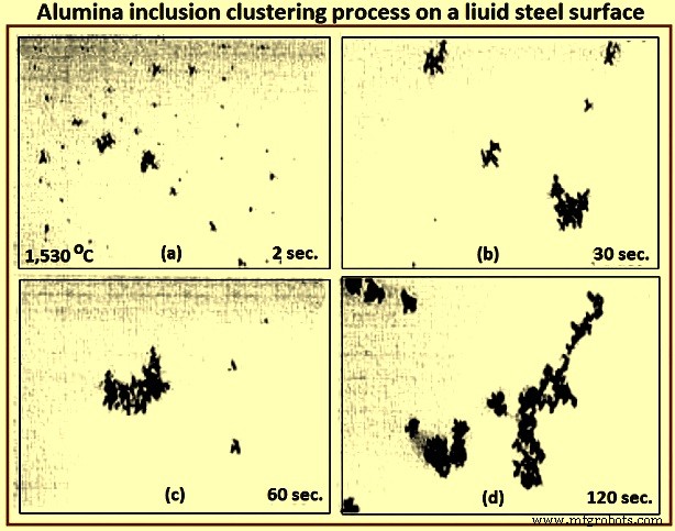
Fig 4 Alumina inclusion clustering process on a liquid steel surface
Electromagnetic visualization (EV) – This Lorentz-force-based detection system is used to accelerate inclusions to the top free surface of the sample of liquid metals and highly conductive opaque fluids. The technique has better resolution than other on-line methods.
Indirect methods
Owing to the cost, time requirements, and sampling difficulties of direct inclusion measurements, steel cleanliness is normally measured in the steel plants using total oxygen, nitrogen pickup, and other indirect methods.
Total oxygen measurement – The total oxygen in the steel is the sum of the free oxygen (dissolved oxygen) and the oxygen combined as inclusions. Free oxygen or ‘active’ oxygen can be measured relatively easily using oxygen sensors. It is controlled mainly by equilibrium thermodynamics with deoxidation elements, such as aluminum. Since the free oxygen does not vary much for example, 3 ppm to 5 ppm at 1,600 deg C for aluminum killed steel. The total oxygen is a reasonable indirect measure of the total amount of oxide inclusions in the steel since there is small population of large inclusions in the steel sample. Hence, the total oxygen content really represents the level of small oxide inclusions only. The total oxygen measured from liquid samples roughly correlates with the incidence of slivers in the product. In particular, tundish samples are normally taken to indicate cleanliness for the cast steel dispositioning.
One of the steel plants needs the total oxygen in the tundish samples less than 30 ppm to ensure shipment of cold-rolled sheet without special inspection. The general conclusions drawn from the data of the total oxygen levels in LCAK steel at each processing step at several steel plants are (i) total oxygen in LCAK steel has steadily decreased with passing years, as new technology is implemented, (ii) plants with RH (Rurhstahl Heraeus) degassing unit achieve lower total oxygen (10 ppm to 30 ppm) than plants with ladle gas stirring (35 ppm to 45 ppm), and (iii) the total oxygen normally drops after every processing step such as 40 ppm in the ladle, 25 ppm in the tundish, 20 ppm in the mould, and 15 ppm in the cast product. Fig 5 shows relationship between total oxygen in tundish and sliver defect index.
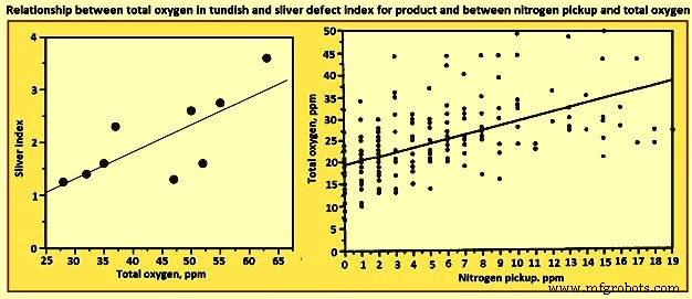
Fig 5 Relationship between total oxygen in tundish and sliver defect index for product and between nitrogen pickup and total oxygen
Nitrogen pickup – The difference in nitrogen content between steelmaking vessels is an indicator of the air entrained during transfer operations. Hence, nitrogen pickup serves as a crude indirect measure of total oxygen, steel cleanliness, and quality problems from reoxidation inclusions. For example, a steel plant restricts nitrogen pickup from ladle to tundish to less than 10 ppm for critical clean steel applications. The oxygen pickup is always many times higher than the measured nitrogen pickup, because of its faster absorption kinetics at the air steel interface. Fig 3 shows relationship between nitrogen pickup and total oxygen. In addition, nitrogen pickup is faster when the oxygen and sulphur contents are low. Hence, for the reduction of the nitrogen pickup, deoxidation is best carried out after tapping. Plant measurements confirm this, as nitrogen pickup reduced from 10 ppm to 20 ppm for deoxidation during tapping to 5 ppm after tapping.
The general conclusion drawn from the data of minimum nitrogen pickup and nitrogen contents measured in LCAK steel at every processing step (except tundish and mould) for several steel plants is that the nitrogen in LCAK steel cast products is around 30 ppm to 40 ppm at the majority of the steel plants. It is controlled mainly by the steelmaking converter or electric furnace operation, but is also affected by secondary steelmaking and shrouding operations. However, the nitrogen pickup is decreasing with passing years, because of new technologies and improved operations. Nitrogen pickup can be normally controlled at 1 ppm to 3 ppm from ladle to the mould. With optimal transfer operations to lessen air entrainment, this pickup can be lowered during steady state casting to less than 1 ppm.
Concentration measurement – For LCAK steels, the dissolved aluminum loss also indicates that reoxidation has occurred. However, this indicator is a less accurate measure than nitrogen pickup since aluminum can also be reoxidized by the slag. The silicon pickup, manganese pickup can be also used to evaluate the reoxidation process.
Lining refractory observation – Analysis of the lining refractory composition evolution before and after operations can be used to estimate inclusion absorption to the lining and the lining erosion. Also, the origin of a complex oxide inclusion can be traced to lining refractory erosion by matching the mineral and element fractions in the slag with the inclusion composition.
Slag composition measurement – Analysis of the slag composition evolution before and after operations can be interpreted to estimate inclusion absorption to the slag. Also, the origin of a complex oxide inclusion can be traced to slag entrpment by matching the mineral and element fractions in the slag with the inclusion composition. However, these methods are not easy because of the sampling difficulties and since changes in the thermodynamic equilibrium are to be taken into account.
Tracer studies for determining exogenous inclusions from slag and lining erosion – Tracer oxides can be added into slags and linings in ladle, tundish, mould, or ingot trumpet, and top compound. Typical inclusions in the steel are then analyzed by SEM and other methods. If the tracer oxides are found in these inclusions, then the source of these inclusions can be decided.
Submerged entry nozzle (SEN) clogging – Short SEN life due to clogging is sometimes an indicator of poor steel cleanliness. The composition of a typical clog during LCAK steel continuous casting consists of Al2O3- 51.7 %, Fe – 44 %, MnO – 2.3 %, SiO2 – 1.4 %, and CaO – 0.6 % , which shows that nozzle clogs are frequently caused by a simultaneous build-up of small alumina inclusions and frozen steel. Hence, SEN clogging frequency is another crude method to evaluate steel cleanliness.
Final product tests
The ultimate measure of cleanliness is to use destructive mechanical tests to measure formability, deep-drawing, and / or bending properties of the final sheet product, or fatigue life of test samples or product samples. Other steel sheet tests include the HIC test and magnetoscopy. Another example is the inclusion inspection method in ultra-sonic fatigue test. These tests are needed to reveal facts such as the potential benefit of very small inclusions (less than 1 micrometer), which are not to be counted against cleanliness.
It can be seen from the above that there is no single ideal method to evaluate steel cleanliness. Some methods are better for quality monitoring while others are better for problem investigation. Hence, it is necessary to combine several methods together to give a more accurate evaluation of steel cleanliness in a given operation.
Since exogenous inclusions can originate from a combination of several sources, methods for their prevention are not likely to be simple. It is only through the correct combination of all these sources and removal mechanisms that the incidence of large inclusions in the steels can be reduced. For the detection of the exogenous inclusions in steel, the methods which are suitable are ultrasonic scanning, microscopic observation, sulphur print, slime (electrolysis), X-ray, SEM, slag composition analysis, and refractory observation.
Productieproces
- Effect van insluitsels op de eigenschappen van staal
- Opnames in staal en secundaire staalproductie
- Inclusions, Inclusion Engineering en Clean Steels
- Automatisering, instrumentatie en modellering van continu gieten van staal
- Opwarmovens en hun typen
- Continu gietvorm poeders
- AMPCO® 25 Continu gegoten
- AMPCO® 18 Continu gegoten
- AMPCO® 22 Continu gegoten
- AMPCO® 21 Continu gegoten
- AMPCO® 18.23 Continu gegoten