Nano- en batterijanode:een recensie
Abstract
Het verbeteren van de anode-eigenschappen, inclusief het vergroten van de capaciteit, is een van de basisbehoeften om de batterijprestaties te verbeteren. In dit artikel worden anoden met hoge capaciteit en legeringsprestaties geïntroduceerd, vervolgens wordt het probleem van fragmentatie van deze anoden en het effect ervan tijdens de cyclische levensduur uiteengezet. Vervolgens wordt het effect van het verkleinen tot nanoschaal besproken bij het oplossen van het probleem van fragmentatie en het verbeteren van de eigenschappen, en ten slotte worden de verschillende vormen van nanomaterialen onderzocht. In dit artikel wordt elektrodereductie in de anode, een fenomeen op nanoschaal, beschreven. De negatieve effecten van dit fenomeen op legeringsanoden worden uitgedrukt en er zal worden besproken hoe deze negatieve effecten kunnen worden geëlimineerd door geschikte nanostructuren te maken. Ook worden de anodes van de titaniumoxidefamilie geïntroduceerd en worden de effecten van Nano op de prestatieverbetering van deze anodes uitgedrukt, en ten slotte wordt het quasi-capacitieve gedrag, dat specifiek is voor Nano, geïntroduceerd. Ten slotte wordt het derde type anodes, uitwisselingsanoden, geïntroduceerd en wordt hun functie uitgedrukt. Het effect van Nano op de omkeerbaarheid van deze anodes wordt genoemd. De voordelen van nanotechnologie voor deze elektroden worden beschreven. In dit artikel wordt gevonden dat nanotechnologie, naast de gebruikelijke effecten zoals het verkleinen van de penetratieafstand en het moduleren van de spanning, ook andere interessante effecten creëert in dit type anode, zoals capacitieve quasi-capaciteit, veranderend opslagmechanisme en lagere volumeverandering.
Inleiding
Grafiet is een koolstofmateriaal met een gelaagde structuur waarbij de afstand tussen de lagen ongeveer 35,3 is, waarbij er een geschikte ruimte tussen de lagen is voor de plaatsing van lithiumatomen [1,2,3,4]. Tijdens het opladen worden lithiumionen in de anode gereduceerd en omgezet in lithiumatomen, die tussen de grafietlagen worden geplaatst. Na de komst van lithium bereikt de afstand tussen de platen 3,5 Å [5,6,7,8,9,10]. Tijdens de ontlading worden de lithiumatomen geoxideerd tot lithiumionen en door de elektrolyt naar de kathode getransporteerd. Vanwege het inbrengen van lithiumatomen in grafiet (op het moment van opladen), worden deze materialen intercalatieanoden genoemd [6,7,8,9,10,11,12,13,14]. Volgens figuur 1 kan in grafiet maximaal één lithiumatoom worden opgeslagen per 6 koolstofatomen [5]. Omdat de capaciteit direct gerelateerd is aan de hoeveelheid opgeslagen lithium, heeft grafiet een lagere capaciteit dan lithiummetaalanoden, maar zoals eerder vermeld, wordt het gebruikt als commerciële anode omdat het geen dendritische groeiproblemen heeft. Merk op dat in dit artikel en toekomstige artikelen de anode en kathode de werkzame stof in de anode en kathode betekenen [6,7,8]. Vanwege de lage capaciteit van grafiet zijn anodes met een hoge capaciteit vereist [15,16,17,18]. Een groep anoden die grote hoeveelheden lithiumatomen kunnen opslaan, zijn anodes van het legeringstype gemaakt van metaal of halfgeleiders. De functie van deze anodes is om een legering te vormen met een metaal of halfgeleider, waarbij het lithiumatoom wordt opgeslagen [19,20,21]. In dit type materiaal kunnen, in vergelijking met grafiet, waar slechts één lithiumatoom wordt opgeslagen voor elke 6 koolstofatomen, meerdere lithiumatomen worden opgeslagen voor elk metaalatoom [9,10,11]. De belangrijkste van deze anoden zijn silicium en antimoon. Voor silicium is de capaciteit ongeveer 4000 mAh/g en voor tin is de genoemde capaciteit 900 mAh/g vergeleken met grafiet met een capaciteit van ongeveer 350 mAh/g. Volgens figuur 2 heeft silicium van de legeringsanodes het hoogste volume en het grootste gewicht, wordt het in overvloed in de natuur aangetroffen en is de hele elektronica-industrie gebaseerd op silicium; Dus, zoals figuur 2 laat zien, is silicium de belangrijkste van de legeringsanoden [12,13,14,15]. Daarom gaat het meeste materiaal in dit artikel over silicium, maar de genoemde principes kunnen worden veralgemeend naar andere legeringsanoden. Actief anodemateriaal, theoretische capaciteit, voordelen en studieresultaten worden weergegeven in tabel 1.
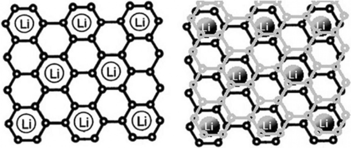
Laat zien hoe lithium wordt opgeslagen in grafiet. Voor elke 6 koolstofatomen wordt 1 lithiumatoom opgeslagen [12]
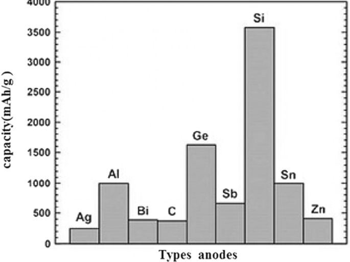
Soorten anodes met capaciteit [13,14,15]
Problemen met legeringsanodes
In deze anoden gaat de opslag en afgifte van lithium gepaard met een grote volumeverandering die kan oplopen tot 400% van het oorspronkelijke volume, zoals weergegeven in Fig. 3. Tijdens de werkcyclus, als gevolg van de spanningen veroorzaakt door volumeverandering, het fenomeen van verpulvering van werkzame stoffen treedt op [7, 10, 39, 40]. Fragmentatie zorgt ervoor dat de verbinding tussen het actieve materiaal zelf, tussen het actieve geleidend-additief materiaal en tussen de actief-verzamelende actieve stof wordt verbroken [18,19,20]. Wanneer dit fenomeen optreedt, wordt de werkzame stof elektrisch geïsoleerd; daarom vindt er geen elektronenoverdracht plaats om de oxidatiereactie uit te voeren. Daarom blijft een groot volume aan actieve ingrediënten ongebruikt en nemen ze niet deel aan de capaciteit, wat uiteindelijk leidt tot een sterke daling van de capaciteit tijdens de werkcyclus [21, 41, 42]. Afbeelding 3 toont het verpletterende fenomeen. Helaas toont figuur 3 niet de volledige structuur van de anode-elektrode. In feite worden in een conventionele elektrode microndeeltjes van actieve materialen gebruikt samen met bindmiddelen en koolstofgeleidende materialen, enz. [43,44,45,46]. Die wordt verbroken als de hierboven genoemde elektronische verbindingen worden verbroken. Figuur 4 toont de laad- en ontlaadcurves voor siliciumdeeltjes van 10 micron. Het is te zien dat de capaciteit zelfs bij de eerste ontlading slechts 800 mAh/g is (vergeleken met de aanvankelijke 4000 opgeladen). In grafiet daarentegen neemt de capaciteit met slechts 0,03 per arbeidscyclus af. Deze anodes hebben een hogere spanning dan grafiet (volgens de eerder genoemde formule geldt:hoe hoger de anodespanning, hoe lager de accuspanning) [10, 21, 39]. Silicium heeft bijvoorbeeld een spanning van 0,3 tot 0,4 hoger dan lithium, terwijl in grafiet de spanning ongeveer 0,05 V hoger is dan lithium, maar anodes van silicium en andere legeringen hebben zo'n hoge capaciteit dat de spanning geen significant effect heeft, en de energie is aanzienlijk hoger dan grafiet.
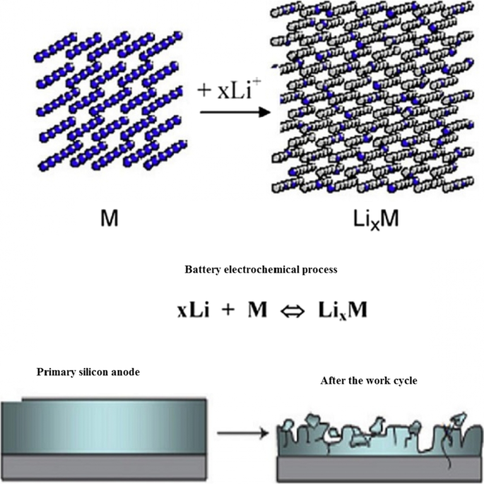
Verpulvering en ontkoppeling van de elektrische verbinding [10]
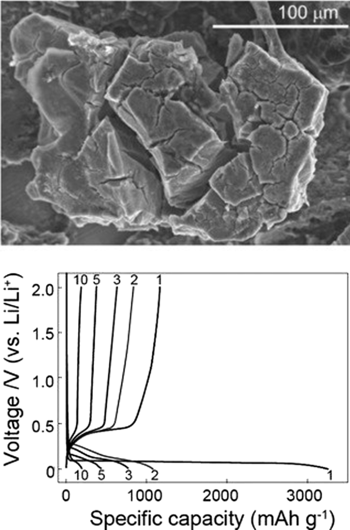
Oplaad- en ontlaadschema voor 10 micron siliciumdeeltjes [17]
Nanotechnologie-oplossing
De prestaties van de batterij kunnen worden verbeterd als het fenomeen van versnippering op de een of andere manier kan worden voorkomen. Onderzoek heeft aangetoond dat wanneer de afmetingen van silicium het nanometerbereik bereiken (minder dan 150 nm), het verpletterende fenomeen niet langer optreedt [47,48,49,50]. Figuur 5 toont het TEM-beeld van silicium nanodeeltjes tijdens lithiumionisatie. Deze twee deeltjes veranderen van volume door het binnendringen van lithium, maar breken niet onder stress [7, 18, 40]. Dit toont aan dat om de buitengewone capaciteit van silicium te gebruiken, we onvermijdelijk naar de nanoschaal moeten gaan [51,52,53]. Als nanodeeltjes worden gebruikt, is het probleem van fragmentatie opgelost, maar ze zijn normaal gesproken niet aangesloten op de elektronentoevoer. Daarom gebruikten de onderzoekers voor het eerst silicium nanodraden die verticaal op een stroomcollector waren gegroeid, zoals weergegeven in Fig. 6 (SEM-afbeelding). Op deze manier kan het probleem van verplettering worden opgelost, omdat er voldoende ruimte tussen de nanodraden is om het volume van elke nanodraad tijdens de duty cycle te veranderen zonder uitgebreide stress te genereren, de diameter van elke nanodraad is ook kleiner dan de kritische dimensie [19] ,20,21,22, 30, 54,55,56]. Zoals bekend, nam de breedte van de nanodraden na legering (invoer van lithium) toe en kregen de zijwanden een textuur, en hoewel er een grote volumeverandering was, trad er geen fragmentatie op [57]. Bij nanodraden vindt elektronenoverdracht (communicatie tussen de stroomafnemer en de werkzame stof) plaats door de lengte van de nanodraden. Omdat de elektronenoverdracht goed is, kan de volledige capaciteit van het actieve siliciummateriaal worden benut [31, 32, 35,36,37]. Nanodraden hebben een hoger elektrolytbindingsseizoen dan bulkmateriaal [41,42,43]. Vanwege het feit dat de oxidatiereactie plaatsvindt via het elektrode-elektrolyt-interface, neemt ook de snelheid van de reacties toe. aan de andere kant, omdat nanodraden kleine afmetingen hebben in vergelijking met het bulkmateriaal dat ionen langere afstanden moeten afleggen, is ionenoverdracht door laterale afmetingen eenvoudig. Snellere ionenoverdrachten en oxidatiereacties verhogen het vermogen en zelfs de energie, omdat ionenoverdracht (soms naast elektronenoverdracht) een potentieel verlies is (concentratiepolarisatie) van zowel de anode- als kathode-elektroden van een lithiumbatterij, deze polarisatie neemt af naarmate de penetratieafstand neemt af en de energiedichtheid verbetert [44,45,46]. Ten slotte, omdat silicium een halfgeleider is, heeft het minder elektronengeleiding dan grafiet, dat een metalloïde is [33, 38, 58].
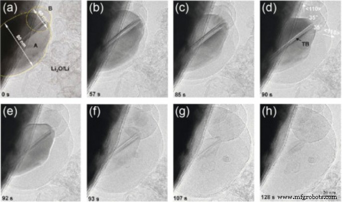
TEM-beeld van silicium nanodeeltjes tijdens lithiumionisatie vorderde van a tot u het lithiumionisatie, respectievelijk [19]
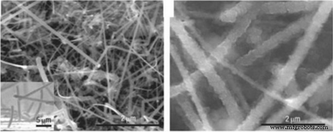
SEM-beeld van silicium nanodeeltjes tijdens lithium [20]
Verschillende nano-morfologieën
Het is aangetoond dat het gebruik van silicium nanobuisjes in plaats van nanodraden effectiever is. In nanobuisjes is aan beide zijden van de binnen- en buitenwand de nodige ruimte voorzien voor volumeverandering [34, 59,60,61]. Bovendien zijn nanobuisjes meestal dunner dan nanodraden, dus zenders zijn beter, omdat silicium een halfgeleider is en ook amorf is tijdens de duty cycle als gevolg van spanningen, geleidt het elektronisch niet goed tijdens de duty cycle [47, 48, 54]. Hierdoor stromen elektronen niet goed door in alle delen van het silicium. Hybride nanostructuren kunnen worden gebruikt om dit probleem op te lossen, bijvoorbeeld een silicium nanobuis waarvan de kern geleidende materialen bevat of omgekeerd een geleidende coating heeft [62,63,64,65,66]. Een vergelijking tussen de twee categorieën van niet-gecoate en met koolstof gecoate siliciumnanodraden heeft aangetoond dat met koolstof beklede nanodraden een aanzienlijke capaciteit behouden. Een andere oplossing is het gebruik van nanocomposietanoden [49,50,51]. Een van de meest gebruikte materialen in nanocomposieten in de rol van stressmodulator (buffer) is koolstof. Koolstof nanocomposiet op het gebied van koolstof is bijvoorbeeld een van de oplossingen voor het stressprobleem. Afbeelding 7 toont een tin-koolstof nanocomposiet. Tin fungeert als een actief ingrediënt als een legeringsanode. Koolstof in deze nanocomposiet fungeert als zowel een buffer als een geleider, en naast hun verschillende koolstofstructuren, kunnen ze ook wat lithium opslaan. Zoals te zien is in Fig. 7, is de tincapaciteit minder dan de theoretische capaciteit (900 mAh/g) vanwege de aanwezigheid van koolstof, maar heeft een goede levensduur. Handhaaft goed tot 1000 werkcycli [52, 67,68,69,70].

TEM-beeld en levenscycluscurve van tin-nanocomposiet in koolstof, donkere tin-nanodeeltjes zijn gemarkeerd [54]
De vraag kan bij de lezer opkomen waarom andere legeringsanoden worden onderzocht, aangezien silicium een veel hogere capaciteit heeft dan andere legeringsanoden [71,72,73]. Het antwoord dat wordt gegeven en kan worden gegeneraliseerd naar de hele verzameling nanotechnologie- en batterijartikelen, is dat nanomaterialen op verschillende manieren en met verschillende morfologieën (vormen) op verschillende manieren worden gesynthetiseerd [74,75,76,77,78]. Elke synthesemethode is anders dan de discussie over prijs, kwaliteit, veiligheid, schaalbaarheid, milieueffecten, enz.; metalen kunnen bijvoorbeeld niet worden bereid met de sol-gel-methode, wat een eenvoudige methode is [79,80,81]. Zelfs voor een specifiek materiaal zoals silicium kunnen eendimensionale nanomaterialen, zoals nanovezels, worden geproduceerd door middel van elektrospinnen, wat een massaproductiemethode is, in de vorm van nanodraden door de dure chemische dampafzettingsmethode, een andere methode voor laboratoriumtests [22, 52,53,54]. Nanodraden kunnen worden vervaardigd door middel van etsen op silicium. Bij de laatste methode kunnen de kristallijne richting en dotering gemakkelijk worden gecontroleerd en kan het effect van verschillende doteringen en kristallijne richtingen op lithiumopslag worden bepaald [23, 82,83,84,85,86,87,88]. Zelfs een nanomateriaal met een specifieke vorm en samenstelling kan op verschillende manieren en zelfs in een specifieke methode worden gebruikt, verschillende reactanten kunnen worden gebruikt met verschillende temperatuuromstandigheden, enz., die elk verschillende resultaten kunnen hebben in termen van prijs, veiligheid en aangezien de sleutel tot commercialisering, behalve investeren, is het vinden van de juiste productiemethode door rekening te houden met de hierboven genoemde factoren, dus er is een onlosmakelijk verband tussen productie en prestaties in batterijen en zeer goede en geschikte artikelen Beschikbaar in verband met de synthesemethode [30, 31 , 56, 57, 89,90,91,92]. Naast eendimensionale nanostructuren (nanodraden en nanobuisjes) is er gestreefd naar het gebruik van nuldimensionale nanostructuren (nanodeeltjes) (aangezien een goed nanodeeltje gemakkelijker te synthetiseren is dan nanodraden). Het probleem met nanodeeltjes is dat het enerzijds niet eenvoudig is om een verband te leggen tussen de nanodeeltjes zelf en anderzijds tussen de nanodeeltjes en het geleidende en verzamelende materiaal [32, 35, 36]. Fig. 8a laat bijvoorbeeld zien dat de primaire nanodeeltjes (links van de afbeelding) in volume toenemen na het absorberen van lithium tijdens het opladen, en na een paar cycli de elektronenverbinding loskoppelen wanneer deze terugkeert naar zijn oorspronkelijke staat zonder lithium [3, 24, 93,94,95]. Bij de gebruikelijke methode voor het bereiden van de anode (ook de kathode), wordt het poeder van de actieve stof (hier silicium) gebruikt samen met de geleidende koolstof (ter verbetering van de geleidbaarheid) en het PDVF-bindmiddel (voor de binding van de deeltjes) weergegeven in afb. 8b. Volgens figuur b, omdat de silicium nanodeeltjes van volume veranderen, na terugkeer naar een andere begintoestand, gaat de elektrische verbinding tussen de nanodeeltjes, het koolstofgeleidende materiaal verloren, de capaciteit wordt verminderd. Om het bovenstaande probleem op te lossen in de methode weergegeven in figuur c, wordt amorf silicium, dat ook een stressmodulerende rol heeft, gebruikt als lijm om silicium nanodeeltjes te binden zodat de elektrische verbinding niet langer wordt onderbroken en de capaciteit behouden blijft [25 , 37, 38, 96, 97]. Bij een andere methode zijn nanodeeltjes op het gebied van polyaniline geleidend polymeer, die zowel een modulerende als elektronengeleidende rol hebben, geprepareerd en waargenomen met een goede levensduur van 1000 met behoud van een capaciteit van 1600 mAh/g. Ter vergelijking:de PVDF-bindmiddelmethode verliest meer dan 50% van zijn capaciteit in 100 werkcycli. Een andere manier om het probleem op te lossen zijn holle nanostructuren. Bij deze methode wordt de nodige lege ruimte voorzien tijdens het in- en uitgaan van lithium door een hol volume [26, 27, 33, 58, 59]. De eindige-elementenmethode laat zien dat de holle structuur in hetzelfde volume minder spanning ondergaat tijdens de werkcyclus, zodat ze beter bestand zijn tegen het verbrijzelingsverschijnsel (Fig. 9).
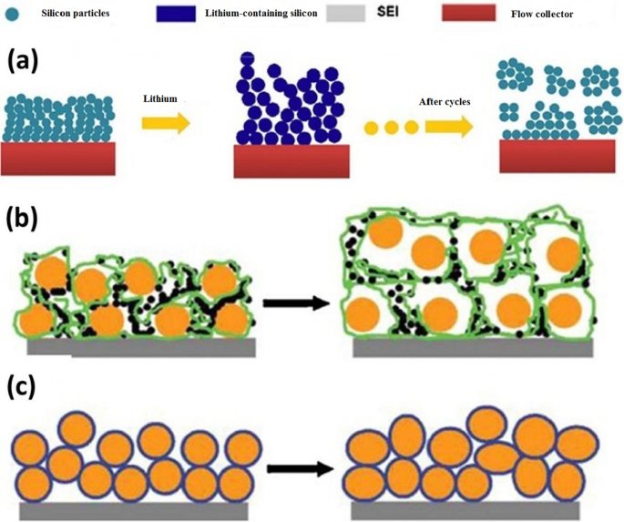
een Laat zien hoe de elektrische relatie van nanodeeltjes met de stroomcollector wordt verbroken, b toont een ander type ontkoppeling, silicium nanodeeltjes in oranje en koolstof in zwart en PDVF-polymeerketens worden in groen weergegeven. c Gebruik amorfe siliconenlijm om nanodeeltjes te hechten, zelfs na vervorming [47].
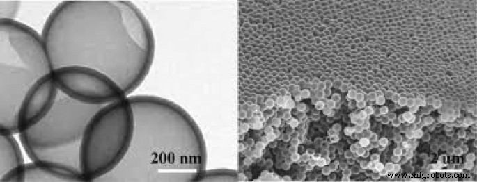
Holle nanodeeltjes om het volumeveranderingsprobleem op te lossen [48]
Elektrolytafbraak in de anode
Zoals we weten, is elke stof stabiel in een potentieel bereik en ondergaat het een reductie- of oxidatieproces dat min of meer binnen dit bereik ligt [28, 98, 99]. Daarom kunnen we water ontleden (elektrolyseren) om waterstof en zuurstof te produceren. Deze cellen zijn het tegenovergestelde van galvanische cellen (batterijen), elektrolytcellen genoemd. In deze cellen geven we, in tegenstelling tot de batterij, energie om een reactie te forceren die thermodynamisch niet wenselijk is [60].
Bij het opladen van de batterij geven we, net als bij het ontbinden van water, energie aan de batterij via de lader om de reactie die in de batterij plaatsvond om te keren en de batterij terug te brengen naar de voor-ontladen toestand [100,101,102,103,104]. De organische elektrolyt die wordt gebruikt in lithium-ionbatterijen (zoals waterelektrolyse) verandert als gevolg van de energie van de lader. Zoals vermeld, vindt in een lithium-ionbatterij, aan de negatieve pool (grafietanode), lithium-ionreductie plaats tijdens het opladen. Vanwege het feit dat de neiging tot elektrolytreductie thermodynamisch hoger is dan bij lithiumionen, wordt elektrolytreductie uitgevoerd in plaats van lithiumionreductie. Hierdoor vormt zich een vaste laag op het grafietoppervlak. Deze vaste laag wordt SEI (solid electrolyte interface) genoemd. De samenstelling van deze laag is complex en een mengsel van verschillende chemicaliën. Afbeelding 10 toont een schematische weergave van deze laag. Zoals te zien is in de figuur, bevat de samenstelling van deze stof lithiumionen en koolstof; daarom gaat de vorming van deze laag gepaard met een afname van lithium, wat de capaciteit in de eerste lading vermindert [34, 61]. Deze laagdikte ligt in het nanometerbereik zoals weergegeven in figuur 10. De vorming van de SEI-laag zelf beperkt de voortzetting van de elektrolytreductiereactie, omdat het voorkomt dat de elektrolytmoleculen het oppervlak van de grafietanode bereiken als een fysieke barrière. In feite werkt het als een kinetische remmer (zoals de passieve laag van aluminiumoxide, die voorkomt dat zuurstof het lagere aluminium bereikt en voorkomt dat de rest van het aluminium oxideert). Aan de andere kant, omdat het een elektronenisolator is, voorkomt het ook dat het elektron de elektrolyt bereikt [62,63,64,65]. Daarom kan noch het elektron het elektrolytmolecuul bereiken, noch kan het elektrolytmolecuul naar het elektron in de anode toe bewegen, die beide ervoor zorgen dat het elektrolyt regenereert en een zelfbeperkende reactie heeft. Gelukkig is deze laag doorlaatbaar voor lithiumionen, en lithiumionen kunnen er doorheen gaan naar het anode-oppervlak, elektronen vangen en regenereren [105,106,107,108]. Deze laag vermindert het batterijvermogen omdat het de penetratieafstand van de lithiumionen om de anode te bereiken [109,110,111] vergroot.
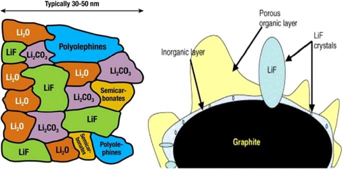
Schema van SEI-vorming en samenstelling van deze laag [66]
Afbeelding 11 toont het bereik van elektrolytstabiliteit ten opzichte van de potentiaal van anodes en kathoden. Als de kathode een potentiaal heeft die hoger is dan het elektrolytstabiliteitsbereik, wordt het elektrolyt geoxideerd aan de kathode en tijdens het opladen, en ook als de anode een lagere potentiaal heeft dan het stabiliteitsbereik, wordt het geregenereerd aan de anode en tijdens het opladen van het elektrolyt. Gelukkig hebben conventionele kathoden, zoals weergegeven in figuur 11, niet het probleem van elektrolyt-instabiliteit, maar in grafiet- en siliciumanoden is er instabiliteit en wordt SEI gevormd [66,67,68].
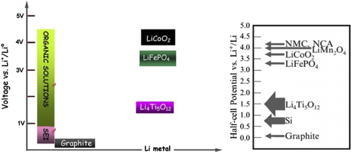
Toont de spanning van gemeenschappelijke anoden en kathoden en het bereik van elektrolytstabiliteitspotentieel en het potentiële bereik van SEI-vorming [67]
SEI-probleem in silicium
In het algemeen is voor anoden van minder dan één volt ten opzichte van lithiummetaal de elektrolyt onstabiel en wordt SEI gevormd. Daarom wordt SEI gevormd in de siliciumanode, die een potentiaal van 0,3 tot 0,4 hoger heeft dan lithium [112.113.114.115]. Helaas, omdat silicium van volume verandert en afbreekt, worden nieuwe niveaus van silicium blootgesteld aan de elektrolyt, zodat het elektron de elektrolyt bereikt en een nieuwe SEI wordt gevormd op deze nieuwe oppervlakken. Als gevolg hiervan wordt de capaciteit tijdens werkcycli voortdurend verminderd. Het is nodig om dit te zeggen, omdat er vaak tests worden uitgevoerd op lithiummetaal, worden in alle batterijartikelen spanningen ten opzichte van lithium gemeten [69]. In silicium nanomaterialen is het vanwege de hogere chemische activiteit nog gevoeliger voor de vorming van SEI. In het geval van nanomaterialen is het waar dat ze niet afbreken, maar wel van volume veranderen. Volgens figuur 12 zorgt deze volumeverandering ervoor dat SEI continu groeit en zien we de nadelen van SEI-groei, zoals verminderde capaciteit en vermogen, enzovoort. Afbeelding 13 van sectie a illustreert beter de reden voor SEI-groei in nanomaterialen. Als we de doorsnede hebben van een nanodraad (of nanodeeltjes, enz.) in de begintoestand zonder lithium, weergegeven aan de linkerkant van de figuur, tijdens het opladen, omdat het silicium lithium bevat, neemt het volume toe en door elektrolyt instabiliteit tegelijkertijd wordt er een SEI-laag gevormd op de nanodraad [116,117,118,119]. Nu komt tijdens het ontladen het lithium naar buiten en het deeltje krimpt terwijl de SEI niet krimpt. Dit zorgt ervoor dat de SEI afbrokkelt onder stress (of zelfs in de tweede fase van siliciumvergroting onder lithiumionisatie, op welk punt spanning optreedt en de SEI afbrokkelt omdat de exacte grens tussen de SEI en het deeltje niet precies overeenkomt). Daarom wordt bij het opladen (lithiumionisatie) weer een nieuwe SEI-laag gevormd. Herhaling van deze cyclus leidt tot continue SEI-groei en we hebben problemen met de groei, terwijl in grafiet SEI niet zou groeien zonder een kleine verandering in het volume. Opgemerkt moet worden dat wat gezegd is over SEI en silicium ook geldt voor anodes van andere legeringen [70, 120,121,122,123]. Zoals te zien is in paragraaf b, bestaat dit probleem ook voor silicium nanobuisjes, maar als we op de een of andere manier kunnen voorkomen dat het silicium vanaf het begin in contact komt met de elektrolyt en het volume in de buurt van de elektrolyt verandert, is dit probleem opgelost.
Hoe de SEI-laag groeit [19]
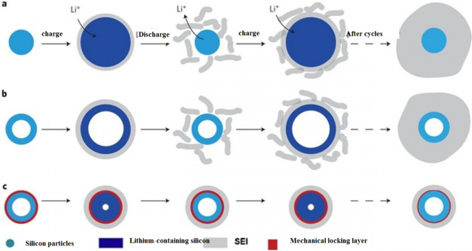
Toont de groei van SEI in verschillende omstandigheden [20]
Wu et al. [18] gebruikte een mechanische vergrendelingslaag zoals weergegeven in Fig. 13c; deze laag, die is gemaakt van siliciumoxide, verhindert de verandering in het buitenste volume van de nanobuisjes vanwege zijn mechanische sterkte. Zo wordt een stabiele SEI gevormd zonder het volume te veranderen (een stabiele SEI-laag zoals grafiet). Deze oxidelaag is de geleider van lithiumionen en is dus geen probleem om te reageren. De benodigde ruimte voor volumeverandering wordt ook verschaft door de binnenwand van de nanobuis. Er is dus geen probleem met verpletteren. Omdat uit het onderzoek bleek dat het elektrolyt niet in het nanobuisje dringt, is er geen contact tussen het elektrolyt en de binnenwand van het nanobuisje. Al deze voordelen zorgen ervoor dat het een lange levensduur en een goed vermogen biedt. Afbeelding 14 (in deze afbeelding weergegeven met DWSiNT) toont een deel van de diepe ontladingscycli van dit monster. Bij diepontlading wordt de levensduur altijd sneller verkort. Er wordt echter waargenomen dat het voorbereide monster na 900 cycli nog steeds een goede capaciteit heeft, maar de normale nanobuisjes en nanodraadmonsters snel hun capaciteit verliezen. Ontladen) Voor het uitgezette monster laat het zien dat de capaciteit zijn capaciteit behoudt, zelfs na deze relatief hoge C-snelheid, zelfs bij maximaal 6000 open cycli. In een ander voorbeeld [19] wordt een kern-schaalstructuur gemaakt, zoals weergegeven in Fig. 15c, wordt een koolstofcoating gebruikt met siliciumnanodeeltjes in de koolstofcoating. De dikte van de koolstofcoating ligt in het bereik van 10 nm en bevat 100 nm siliciumdeeltjes. De koolstofschaal is voorzien van voldoende ruimte om het volume van het siliciumnanodeeltje gemakkelijk te veranderen, zoals weergegeven in figuur c. Aan de andere kant zijn silicium nanodeeltjes vanaf één punt aan de koolstofschil bevestigd, dus daarin vinden elektronen- en ionische overgangen plaats, omdat koolstof zich in de buurt van de elektrolyt bevindt en niet silicium, zoals grafiet, wordt een stabiele SEI gevormd zonder te verpletteren omdat de verandering in volume van silicium niet wordt overgedragen naar koolstof en van koolstof naar SEI, dus vergelijkbaar met de figuur in Fig. 12, heeft het een lange levensduur. Als we normaal siliciumnanodeeltjes gebruiken, naast het SEI-probleem, zoals we in het vorige artikel en figuur a zagen, blijkt dat er geen lege ruimte tussen de siliciumnanodeeltjes is om het volume te veranderen, dus er is spanning tussen de deeltjes wanneer ze veranderen van volume, maar bij gebruik van deze holle structuur (Figuur b) is er geen spanning meer tussen de deeltjes.
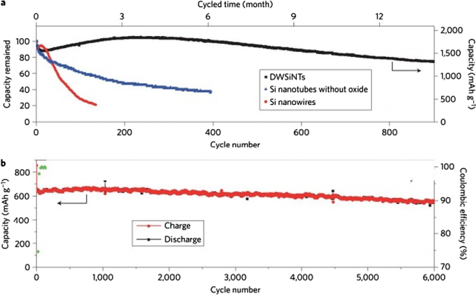
een Vergelijking tussen de levensduur van zwart, blauw en rood voor oxidegecoate, b respectievelijk oxidevrije en niet-oxide nanobuisjes [21]
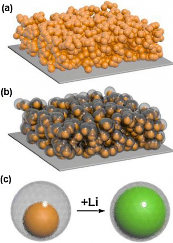
een Weergave van elektroden gemaakt van silicium nanodeeltjes. b Elektrodendisplay van silicium nanodeeltjes met koolstofcoating en holle structuur. c De structuur van de kern-holle schaal gebruikt in b , het silicium bevindt zich in de holle koolstof en de volumeverandering ervan wordt waargenomen tijdens lithiumionisatie [10]
Deze anode heeft andere voordelen naast het SEI-probleem, vergeleken met het monster in Fig. 12. Een voordeel van de synthese van nanodeeltjes ten opzichte van nanobuisjes, en nog belangrijker, het gebruik van nanodeeltjes in vergelijking met nanodraden, is goed compatibel met de slurrymethode, wat de conventionele methode is om elektroden in batterijen te maken.
Introductie van LTO-anode
Tot nu toe hebben we het gehad over twee soorten grafietanodes en anoden van legeringen (silicium). Een andere zeer populaire anode is de anode met Li4Ti5O12 compound, kortweg LTO genoemd. Deze anode is als intercalatiegrafiet [29, 124,125,126,127]. Afbeelding 16 toont de structuur en reactie van dit type anode. De LTO-anode heeft een beperkte capaciteit van 175 mAh/g (vergeleken met 300 grafiet en 4000 silicium). De spanning van deze anode is ook ongeveer 1,5 V vergeleken met lithiummetaal volgens Fig. 17 (hoe lager de anodespanning, hoe hoger de batterijspanning). Deze hoge spanning en lage capaciteit zorgen ervoor dat deze anode een zeer lage energie heeft, maar het is nog steeds een stap voor op silicium in commercieel opzicht. One of the most important features of this anode is the safety issue, because in electric vehicles there are unpredictable conditions, and the other is the long cycle life, and finally its power [72, 73, 128,129,130].
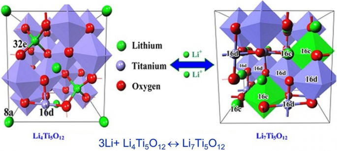
Shows the structure and entry of lithium ion in LTO along with its reaction [74]
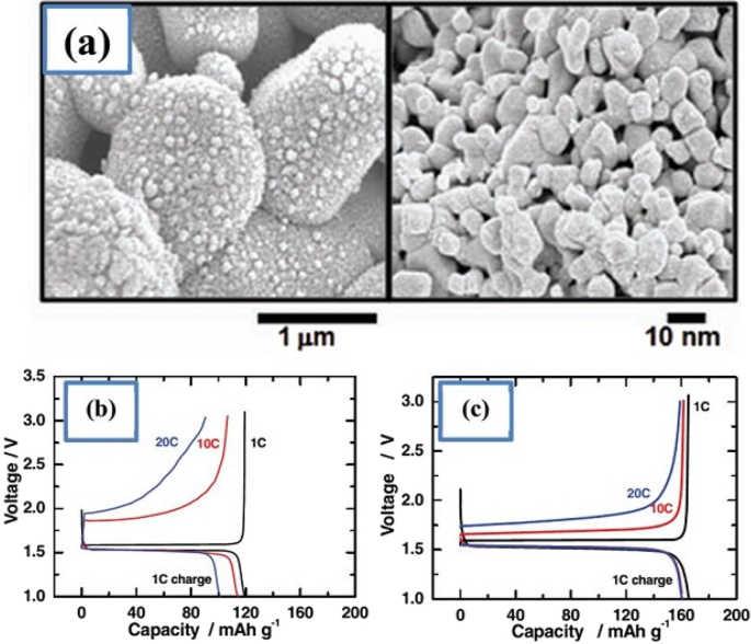
a Displays the nanostructure discussed including Nano primary nanoparticles, b charge–discharge curve for ordinary micro particles, and c for a-shaped particles [74]
Due to the fact that the voltage of this anode is high, it is in the range of electrolyte stability according to Fig. 17, so SEI is not formed. On the other hand, as shown in Fig. 17, there is enough space for lithium ions in this composition and it does not change volume, while even in graphite, some volume change is seen due to the entry and exit of lithium. Unlike the previous two anodes, lithium ions (not lithium atoms) are stored in this anode, and the oxidation reaction is due to the conversion of titanium to 3-valent titanium, not to a change in lithium capacity [28, 74, 75, 131].
This battery, because it has neither SEI nor volume change, maintains the capacity well and has a very long cycle life (more than graphite) of about 20,000 cycles. Because it is an oxide compound and is very safe due to the lack of volume change. Because it does not have SEI, its power is not bad either, only its lithium ion diffusion coefficient is low and its electron conductivity is poor. To solve this problem, they provide LTO nanostructures. Because this anode did not have SEI from the beginning, when it becomes Nano, it does not have the problem of forming more SEI, so it does not have more nanomaterial activity [32, 35,36,37].
It has been observed that nanoparticles cause the LTO anode to charge and discharge within 5 min (12C). To prepare the nanostructure, first titanium oxide nanostructure is prepared and then reacted with a lithium source material when heated. This is also an advantage of LTO, as the preparation of TiO2 nanostructures is very popular. Due to the problem of low volumetric density and agglomeration of nanomaterials, micron secondary particles made from nanoscale primary particles are more useful [33, 38, 58, 59].
Figure 17 shows part an of this nanostructure. As can be seen, from the controlled community of smaller particles measuring 10 nm, larger micron particles are formed. According to the comparison of parts b and c in Fig. 17, it is quite clear that this nanostructure is superior to ordinary micron particles, because it has less capacity and potential (especially in discharge). From this nanostructured anode, a battery is made and it is observed that this battery is superior to the battery with graphite anode both in terms of cycle life and power, which is not given due to the brevity of these curves [75]. The benefits of Nano-LTO have been well documented in many articles, but what makes it stand out is an important discussion of proper engineering of the structure, proper synthesis method, and how to use the conductive material to improve conductivity for further improvement. The future will be talked about. In addition, it is not disputed that nanotechnology is useful for LTO, but many of the phenomena that occur at the nanoscale for LTO are discussed so that some are not fully understood.
Another phenomenon that occurs at the nanoscale is the change in charge–discharge curves for the LTO anode. This anode provides a constant voltage over a wide range of capacities (red box in Fig. 18). When LTO ions are Nano, the constant voltage range decreases until after a critical limit (in the range of a few nanometers) there is no longer a constant voltage range [76].
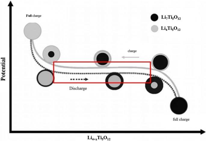
Shows the linear curve range at the LTO anode in the charge–discharge axis [75]
One of the things that happens on the surface is the insertion of more lithium ions into the surface layers. In the surface after insertion, we reach the formula Li8.5 Ti5 O12 , which is 1.5 mol more than the inner layers with the formula Li7 Ti5 O1 , but in the micron material, because the percentage of surface is not high, it shows its effect, but for Nano, because the amount of surface is large, the effects are large. There are several on the charge–discharge curve.
TiO2 Anode
There is also a TiO2 anode from the LTO family. These anodes are easier to synthesize, and because they do not want to react with heat-induced lithium ion precursors, they do not have heat-induced problems such as nanomaterial growth. In addition, according to the chemical formula, titanium oxide has a capacity of twice the amount of 335 mAh/g (LTO). The general response of these anodes is \({\text{TiO}}_{2} + x{\text{Li}}^{ + } + xe^{ - } \leftrightarrow {\text{Li}}_{x} {\text{TiO}}_{2} .\)
TiO2 has four types of phases or crystallographic structures (different atomic arrangements) known as Brocket, Anastasi, Rutile, and (TiO2 (B). The Brocket phase does not matter to the battery. Antara and rutile, which are very popular phases, are important as anodes. Phase (TiO2 (B) performs better than others due to its atomic open space and suitable channel for ion transport, and is the most important [75, 76, 132,133,134,135,136].
If we consider the theoretical capacity based on the chemical formula (one mole of lithium ion per mole of TiO2 ), it is equal to the above value, but based on the phase and position that can be placed according to the lithium ion crystal lattice, different theoretical capacities for different phases have been reported; for example, for anisate, according to network sites, the half-capacity is high, 0.5 mol of lithium ion per mole of TiO2 , 167 mAh/g.
Because all of these phases have poor ionic conductivity, the nanoscale is very effective in increasing both power and capacity. What is interesting is that the nanostructured capacity of Anastasi is more than the theoretical capacity based on the position of the network, but it is definitely less than the theoretical capacity of Formula 334 in all phases. Rutile in micron mode can only store 0.1 mol of lithium ion per grid unit. In rutile, lithium locations are located throughout the network, but the diffusion coefficient in the direction of the c -axis is one order of magnitude greater than that of the ab plate [137,138,139,140,141]. The lithium atom penetrates well in the direction of the c -axis, but must be diffused throughout the space by penetrating the ab plane, and because the diffusion velocity is low in the ab plane, lithium ions accumulate in the c channel, causing a charge repulsive force. Lithium ion positive is generated. This repulsive force prevents more ions from entering the network. As an interesting result of the Nano effect, it has been shown that when the dimensions of rutile become Nano, the capacity reaches 0.8 mol of lithium ion, which has a reversible capacity during different cycles, which reduces the penetration distance and the effect of its quadratic power [142,143,144,145,146]. There is no repulsive force. Figure 19 shows the charge and discharge curves and the cycle life for rutile bulk (micron), commercial rutile micro particles, and rutile nanowires. As can be seen, nanowires show good cyclic longevity and capacity. The shape also confirms that the shape of the nanomaterials also affects the performance of the anode. Morphology such as nanoparticles, nanowires, etc. differ in both capacity and life cycle and power, but the type of morphology alone is not decisive but the geometry of the structure that determines the performance (in the future about the geometry of the structure for all active materials for example, nanowires connected to a current collector, nanowires mixed with graphene, and insulated nanowires each present different results. In addition, there are test conditions and C rate and many other factors [77]. Phase (TiO2 (B), which is newer than other phases, offers the best power and capacity due to its suitable channels for lithium ion transport [147,148,149,150,151]. Figure 20 shows the structure of the penetration site. The capacitance can be significantly increased. This phase offers the best power and capacity among all titanium anodes including LTO, so that by Nano partying it in just 4.5 s, the anode can be charged or discharged with a capacity of 73% of theory. We do not have volume change in this anode either.
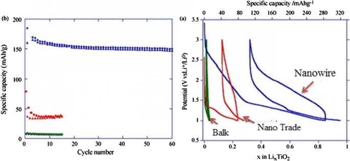
a Charge–discharge curve for the first time, b cycle life [77].
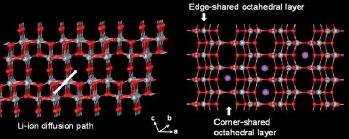
Showing the atomic structure of the phase (TiO2 (B) [77]
Quasi-capacitive Capacity
So far, it has been discussed about the storage capacity of lithium ions in the form of a degree in the nuclear network, and this capacity is improved in the nanoscale due to the reduction of the penetration distance, and so on [152,153,154,155]. But one of the interesting phenomena that occurs for these anodes at the nanoscale is the storage of lithium ions at the surface due to the large surface-to-volume ratio. This type of storage is different from the insert and alloy capacity mentioned so far. This type of storage is very fast because it does not require penetration, and also because it does not create stress and the like, it has the best cycle life and power compared to other lithium storage methods [156,157,158]. Of course, this type of capacity generates less energy. This capacity is discussed in more detail in the topic of super capacitors. The Fig. 21 shows a comparison between the storage capacity of LTO capacity in three different Nano dimensions [78]. According to Fig. 21 in small Nano dimensions, this capacity is significant and decreases significantly with increasing dimensions. It should be noted that capacitive capacitance is not only related to titanium oxide compounds but is also present in many other active substances that are mentioned when introducing them.
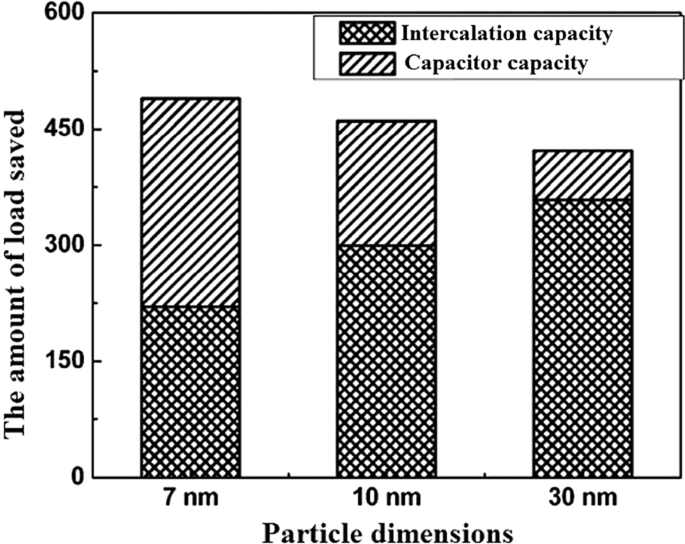
Demonstration of input and super capacitor capacities in titanium oxide [78]
Introduction of Exchange Anodes
So far, we have talked about two types of insert electrodes and alloys. The third type of electrode operation is based on a conversion reaction. Figure 22 shows the mechanism and reaction of this type of electrode. In this form, M (or Me) is an intermediate element that is oxidized, and X is an anion such as oxygen, sulfur, and the like [159,160,161]. The advantage of these anodes is that for every MxXy unit, n lithium ions (n more than one) are involved in the reaction, whereas in the graphite insert anodes we see one lithium ion for every 6 carbon atoms stored in titanium compounds. A maximum of one lithium ion is stored per TiO2 formula unit. But in the exchange anode, for example, for CoO and FeO, the value of n is equal to 2, and in Co3 O4 , the value of n is equal to 8. Figure 23 shows a number of exchangeable oxide anodes with their reaction and capacity [22, 30, 55].
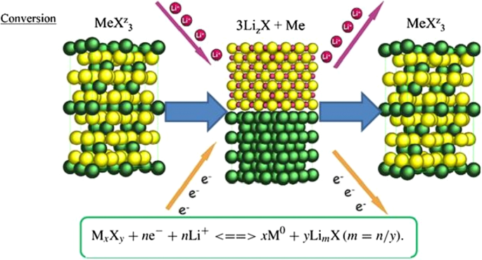
Shows the structure and entry of lithium ion with its reaction [22]

Shows the reaction and capacity of a number of conversion oxide anodes [30, 55]
Exchange Anode Problems
Exchange anodes are very similar to alloy anodes, as alloys have problems with volume change, fragmentation, and SEI formation. In these anodes the ionic and electron conduction is low, and in addition the exchange rate is slow. This low speed leads to high potential during charging and discharging. At these potentials, there is a large difference between the charging and discharging voltages, called hysteresis, which is shown in Fig. 24 with a red arrow. This figure shows that in the first stage of lithium extraction, the anode behavior is significantly different from the next stage of charge and discharge. The hysteresis in this type of anode is up to one volt, while in the graphite and LTO anode it is about 0.2 V. This hysteresis is mostly due to activation polarization [78, 79].
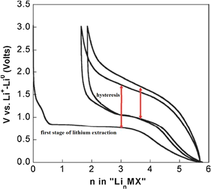
Show charge–discharge curves of exchange anodes [79]
Nano Sizing Effects
Figure 25 shows the lithium ionization behavior (in the test mode, against lithium metal) for anodes made of fine nanoparticles (20 nm) and micro-nanoparticles (500 nm) of iron oxide (SEM) images of these particles in Fig. 26. Available it can be seen that the capacity of the Nano anode is slightly higher. More importantly, it can be seen that the charge–discharge behavior of these two anodes is very different from each other, which is examined in Fig. 26. Figure 26 shows the charge–discharge curves in different cycles as well as the cycle life for the same samples in Fig. 25 to determine the reason for the difference in charge–discharge curves in Fig. 25. Note that instead of capacity, lithium that enters and leaves (which, according to the arguments, represents capacity) is used. In the charge–discharge curves of Fig. 26, lithium ionization continued only up to 1 mol because its purpose was to investigate the behavior in this range of lithium ions. As can be seen, the effective surface mass for the material is only 2 m 2 /g while for the Nano it has an effective surface area of 60 m 2 /g, which indicates how much higher the effective surface area is at the Nano. The difference between Nano and Nano performance is also quite clear. As shown in Fig. 26, the amount of reversible lithium (which can be removed during charging) for Nano is much higher than the corresponding amount for bulk. This shows that the capacity that can be recovered after the initial charge is much better in Nano than in micro. Also, according to the same figure, in the next consecutive charge-discharges, the amount of lithium entering and leaving is less than 0.25 (from 0.75 to 1), while for Nano, the amount of lithium entering and leaving is more than 0.5 (the amount of lithium ion). In the composition it has changed from the range of less than 0.5 ions to 1 ion), according to this, the capacity offered in Nano is much more than bulk. In the micron-sized anode of Fe2 O3 (hematite), before the exchange reaction begins, about 0.1 mol of lithium ion per mole of oxide compound can be stored in the lattice, but above this critical limit, the exchange reaction takes place; on the other hand, when we increase the dimensions of iron oxide particles to 20 nm, the amount of lithium stored in degrees reaches 1 mol, which causes a volume change of only about 1%. Of course, about 0.5 mol is reversible (Fig. 25). In fact, the type of storage mechanism (input, exchange, etc.) changes and the type of mechanism affects the shape of the charge–discharge curve. The above paragraph indicates that when the oxide dimensions enter the Nano field, the storage mechanism is also affected. So far it has been said that Nano makes volume change easier without failure, but here it can be seen that even Nano has reduced the amount of volume change from a few percent for the exchange reaction to one percent for a degree reaction. The reason for this change is the storage mechanism for iron oxide due to thermodynamic problems. The opposite happens for the Co3 O4 anode because it is kinetic and is related to the current density (the current density is obtained by dividing the current by the surface); when the current is constant, in the Nano-dimensions, because the surface is higher, the current density decreases and the Co3 O4 anode shows exchange behavior, but in the micro, due to the high current density, the anode shows the insertion behavior [76,77,78,79].
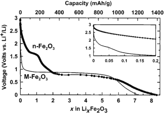
Demonstration of lithium ionization for n -Fe2 O3 and micro-M-Fe2 O3 [80]
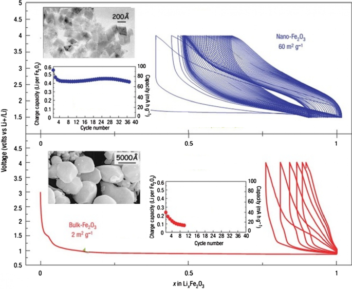
Display of SEM images, charge–discharge curves and cycle life for Nano-iron oxide and bulk [80]
It can be seen from Fig. 26 that at the nanoscale, the cycle life is also much better than bulk. The reason for the improvement of these expressed properties is the ease of volume change and release of stress, ionic and electronic transitions are easier due to the reduction of the penetration distance, which was expressed in this series of articles. Due to high hysteresis, less attention has been paid to compounds with hysteresis [22, 51,52,53,54, 80].
Nanomaterials in Batteries
Nanomaterials have been widely applied in the life sciences, information technology, the environment, and other related fields. Recently, nanostructured materials have also attracted attention for application in energy storage devices, especially for those with high charge/discharge current rates such as lithium ion batteries. The development of next-generation energy storage devices with high power and high energy density is key to the success of electric and hybrid electric vehicles (EVs and HEVs, respectively), which are expected to at least partially replace conventional vehicles and help solve the problems of air pollution and climate change. These energy storage technologies will rely on innovative materials science, i.e. developing electrode materials capable of being charged and discharged at high current rates. Generally, the potential advantages of nanostructured active electrode materials can be summarized as follows:new reactions can be used that are not possible with bulk materials; a larger electrode/electrolyte contact area, leading to higher charge/discharge rates; short path lengths for both electronic and Li ion transport (permitting operation even with low electronic or low Li ion conductivity, or at higher power); etc. Here, we review some recent experimental results that show the advantages of nanostructured active electrode materials [147]. Table 2 summarizes the nanotechnologies that are used to produce nanomaterials, such as mechanical ball milling, chemical vapour deposition, the template method, electrochemical deposition, hydrothermal reaction, dehydration, sintering, pulsed laser deposition, ultrasound, sol–gel synthesis, and micro emulsion.
The first group of applications of nanotechnology in batteries is itself divided into two categories:the first group nanoscale the active substance in the electrode, the second group use nanotechnology to improve the performance of electrodes (cathode or anode) by adding nanomaterials other than the active substance, or the use of Nano coatings. For example, Nano-dimensional additives such as Nano carbons, graphene, carbon nanotubes, etc. have better electron conduction, or the use of Nano-thick coatings on the active material to prevent unwanted reactions with the electrolyte, stress modulation, provide stability and …. for it. For example, for a LiFePO4 cathode, the amount of electron conductivity is poor. Conductivity is improved by using a conductive carbon coating on its particles or by using a conductive carbon material as an additive, A Nano-thick coating of oxide is used [83, 94, 172,173,174,175,176,177]. For example, for a LiFePO4 cathode, the amount of electron conduction is poor, Conductivity is improved by using a conductive carbon coating on its particles or by using a conductive carbon material as an additive, or the LiCoO2 cathode is unstable at high currents in the vicinity of the electrolyte, using a Nano-thick oxide coating to stabilize it [162, 163, 178, 179]. If we want to illustrate the field of nanotechnology in this category with an example, in the same LiFePO4 cathode it has been shown that carbon coating increases conductivity and consequently power, capacity, etc., but one of the areas of research is how to create this coating. Be cheap, effective, etc.; therefore, research in the field of synthesis methods is very important. On the other hand, how to add the same coating and additives to be more effective, so the engineering and architecture of nanostructures is one of the important areas of research and the preparation of these engineered structures is also an interesting issue. Consider Fig. 27 to clarify the matter. This figure shows two types of Nano-engineered structures for the LiFePO4 cathode that use carbon nanotubes to improve conductivity. In addition to differences in performance, each of these structures has a different synthesis method, which indicates the importance of synthesis.
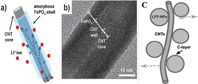
a , b With carbon nanotube core and LiFePO4 wall, and Figure c LiFePO4 nanoparticles attached to carbon nanotube [3, 93]
Silicon has attracted tremendous attentions as one of the most promising candidates for the next-generation Li-ion batteries (LIBs). Compared to the traditional graphite anode, it has many obvious advantages such as large capacity, high abundance and environmental friendliness [1,2,3,4]. Unfortunately, due to the huge volume expansion (~ 300%) in lithiation, silicon particles are pulverized and solid electrolyte interphase (SEI) layers formed on their surface are unstable. Therefore, the long-term cycling stability of silicon anode is poor [5,6,7,8]. Moreover, the low intrinsic conductivity of Si causes unsatisfying rate-capability [9,10,11,12]. Thus, a large amount of Si/metal (e.g., Ag, Cu, Al, Sn) composites have been developed to solve the low conductivity [13,14,15,16]. However, the large volume expansion cannot be relieved effectively. On the other hand, carbon Nano layers are coated on the electrode materials to increase their conductivity, enhance their mechanical strength and provide them stable interfaces with electrolyte. Therefore, various conformal carbon layer coated silicon (Si@C) nanostructures are developed. For example, Si@C with core–shell structure are formed by pyrolyzing various precursors (e.g., pitch, glucose) to coat carbon layers on the pre-prepared silicon nanoparticles [17,18,19,20,21].
Cui et al. designed a hierarchical pomegranate-structured Si@C composite and a nonfilling carbon-coated porous silicon micro particle via the pyrolysis of resorcinol–formaldehyde resin (RF), respectively [23, 82]. And Yu et al. prepared double carbon shells coated Si nanoparticles via chemical vapor deposition (CVD), with acetylene as carbon source [24]. All these designs provide sufficient voids to allow large volume changes of Si during the lithiation/delithiation. However, most of Si@C composites were prepared in separate steps by either pre-coating or post coating carbon on silicon nanomaterials. It led to a complicated preparation strategy.
Continued interest in high performance lithium-ion batteries has driven the development of new electrode materials and their synthesis techniques, often targeting scalable production of high quality nanoceramics (< 100 nm in diameter), which may offer performance improvements. However, there are a number of hurdles, which need to be overcome to move away from current batch synthesis methods that offer poor reproducibility or lack of control over crystallite attributes, particularly at larger scale syntheses. Continuous hydrothermal flow synthesis (CHFS) processes are a promising route for the direct and controlled manufacture of Li-ion battery electrode nanoceramics. Such processes use superheated water and metal salt mixtures as reagents. In a typical CHFS reaction, a feed of supercritical water (above the critical point of water (TC = 374 °C and Pc = 22.1 MPa), is rapidly mixed in an engineered mixer [1] with a metal salt/base aqueous precursor feed (at ambient temperature and the same pressure), resulting in rapid formation of the corresponding nanocrystallite oxide in the water. This nucleation dominated reaction occurs as a result of the metal salts being supersaturated upon mixing with sc-water and also instantly being hydrolysed and dehydrated under these exotic reaction conditions. The nascent nanocrystallite metal oxide stream in water is then cooled in process and then can be constantly collected from the exit of the CHFS process as an aqueous nanoparticle slurry at ambient temperature. The cleaned crystallites (e.g. via dialysis) can be obtained as a wet solid and then freeze-dried to retain maximum surface area and reduce agglomeration. Compared to batch hydrothermal syntheses, CHFS type processes typically produce very small nanoparticles (< 10 nm) with a narrow size distribution [2,3,4]. Additionally, CHFS processes are highly scalable (> 1 kg per hour in the lab of the UCL authors [5]) and can be used to make high quality nanoparticles at scale, with little or no significant variation between those made on the smaller CHFS laboratory scale process.
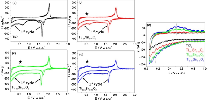
Cyclic voltammetry (CV) measurements at a scan rate of 0.05 mV s −1 in the range of 0.05–3 V versus Li/Li + , are presented in Fig. 28. A pair of cathodic and anodic peaks were observed in the potential range 1.5 and 2.3 V versus Li/Li + , relating to Li-ion insertion into and extraction from the interstitial octahedral site of TiO2 (see equation) [81]. Under normal circumstances, a two-phase reaction is expected to occur during lithiation with phase equilibrium of the Li-poor Li0.01 TiO2 (tetragonal) phase and the Li-rich Li0.55 TiO2 (orthorhombic) phase [19, 20]. The detected specific current peak decreased with higher amount of Sn, thereby reducing the amount of pure TiO2 . The pure TiO2 sample showed virtually no electrochemical activity in the potential range between 1.3 and 1 V versus Li/Li + during the first cycle. The increasing specific current during the first cycle between 1 and 0.05 V versus Li/Li + , is attributed to solid electrolyte interface (SEI) formation (electrolyte destruction) at lower potentials [13]. There was also likely to be substantive SEI formation at the crystallite surfaces of the Sn-doped materials compared to the undoped TiO2 , as there was significant electrochemical activity in the range of 1.3 to 1 V versus Li/Li + for the former. However, as the surface area decreases with higher Sn-loading, the initial capacity loss due to the SEI formation may be expected to decrease. The general trend in fact showed that with higher Sn-loading, the initial irreversible capacity loss increased (from 363 mAh g −1 for the pure TiO2 and 467 mAh g −1 for Ti0.85 Sn0.15 O2 ).

Cyclic voltammograms for the 1st and 2nd cycles for the as-prepared Nano-powder in the potential range of 0.05 and 3 V versus Li/Li + for an applied scan rate of 0.05 mV s −1 for a undoped anatase TiO2 , b Ti0.94 Sn0.06 O2 , c Ti0.89 Sn0.11 O2 , and d Ti0.85 Sn0.15 O2 . e Specific current versus potential of the 2nd cycle for all materials at lower potentials. The specific current was calculated by taking into account the active material mass loadings [81]
Conclusion
- 1.
This article discusses silicon anodes as a representative of alloy anodes. It was observed that the only solution to solve the shredding problem is to use nanotechnology. In this paper, the importance of nanomaterial synthesis was expressed. In summary, how to use nanomaterials with different morphologies to solve the problem and improve power. Although various morphologies were discussed, there was no discussion of structural engineering and the use of carbon conductive materials, which will be discussed in future articles. This was one of the methods of establishing electrical bonding for nanoparticles. There are various structures to prevent the nanoparticles from breaking, the art of which is to create different geometries and the method of their preparation.
- 2.
This article discusses SEI, which is one of the most important topics in most anodes and some high voltage cathodes. This article discussed the problem of alloy anode fragmentation, while which is due to the continuous growth of SEI. It turned out that in order to have a proper cycle life, this problem must be overcome. According to the given examples, using a suitable design at the nanoscale, in addition to providing free volume change of silicon, this volume change does not occur in contact with the electrolyte.
- 3.
The carbon coating on the anode can increase the conductivity from 13–110 to 2.05 S/cm. Doping can enhance performance by increasing the conductivity of electrons and even ions and providing more space within the network along with Nano sizing, which may be appropriate for new projects, which is more a Nano-topic in Nano synthesis than how it accompanies matter. Synthesize with Nano-dimensional doping until there is a discussion about the effect of Nano on improving anode performance. This article discusses titanium oxide anodes, which is one of the most commercially important anodes. It was found that nanotechnology greatly improves the performance of these anodes. Nano sizing has also been shown to affect even the electrochemical and chemical-physical nature (such as charge–discharge curve deformation and greater capacity in surface layers).
- 4.
In this paper, exchange anodes are introduced and their complex operation is described. It was found that many problems, such as alloy anodes, can be solved by Nano damaging the active material. The special effects of Nano were expressed as a change in mechanism.
Availability of Data and Materials
All data generated or analyzed during this study are included in this published article.
Nanomaterialen
- Beoordeling van R, X en Z (weerstand, reactantie en impedantie)
- Betrouwbaarheid en Lean-programma's Power Energizer Battery Plant
- Tinnen nanokristallen voor toekomstige batterij
- Een overzicht van de toepassing van biosensoren en nanosensoren in agro-ecosystemen
- Grafeen- en polymeercomposieten voor toepassingen met supercondensatoren:een recensie
- Hydrothermisch ondersteunde sinterstrategie naar poreus en hol gestructureerd LiNb3O8 anodemateriaal
- Transformatie van slib Si naar nano-Si/SiOx-structuur door diffusie van zuurstof naar binnen als voorloper voor hoogwaardige anoden in lithium-ionbatterijen
- Review:poreuze metalen filters en membranen voor olie-waterscheiding
- Eenvoudige oplossing Synthese van rode fosfor-nanodeeltjes voor lithium-ionbatterijanoden
- 4 redenen waarom lithiumbatterijen beter zijn dan loodzuurbatterijen
- Robots en batterijproductie:een positieve verbinding


