


Analyse door röntgenfluorescentiespectrometrie
Analyse door röntgenfluorescentiespectrometrie
Röntgenfluorescentie (XRF) is een emissiespectroscopische techniek die brede toepassing heeft gevonden op het gebied van elementaire identificatie en bepaling. De techniek is afhankelijk van de emissie van karakteristieke röntgenstraling, normaal gesproken in het energiebereik van 1 keV tot 60 keV, volgend op excitatie van atomaire elektronenenergieniveaus door een externe energiebron, zoals een elektronenstraal, een geladen deeltjesstraal of een x -straalstraal. In de meeste monstermatrices kan röntgenspectrometrie elementen detecteren in concentraties van minder dan 1 microgram/g monster (1 ppm). In een dunnefilmmonster kan het totale hoeveelheden van enkele tienden van een microgram detecteren. Aanvankelijk vond röntgenspectrometrie brede acceptatie in toepassingen die verband houden met metallurgische en geochemische analyses. Meer recentelijk is röntgenspectrometrie waardevol gebleken bij de analyse van omgevingsmonsters, bij de bepaling van zwavel en slijtage-elementen in aardolieproducten, bij toepassingen met forensische monsters en bij metingen van elektronische en computergerelateerde materialen.
Röntgenfluorescentie (XRF) spectrometrie is een veelzijdig hulpmiddel bij veel analytische problemen. Grote, kleine en sporenelementen kunnen kwalitatief en kwantitatief worden bepaald in verschillende soorten monsters, zoals metalen, legeringen, glas, cement, mineralen, gesteenten, ertsen, polymeren, evenals milieu- en biologische materialen. Elementen van natrium (Na) tot uranium (U) worden routinematig bepaald met behulp van energie-dispersieve röntgenfluorescentie (EDXRF) spectrometer, terwijl toepassing van golflengte-dispersieve röntgenfluorescentie (WDXRF) spectrometer een efficiënte bepaling van lage-Z-elementen mogelijk maakt tot zelfs beryllium (Be). Hoewel de monsters zonder behandeling kunnen worden geanalyseerd, kunnen resultaten van hoge kwaliteit worden gegarandeerd als de juiste monstervoorbereiding wordt toegepast. Dit kan variëren van eenvoudig reinigen en polijsten van het monster (metalen, legeringen), poederen en pelletiseren met of zonder bindmiddel (keramiek, mineralen, ertsen, grond, enz.), het smelten van het monster met de juiste flux (keramiek, stenen, ertsen, etc.) tot ontsluiting met zuren (metalen, legeringen). Op deze manier kunnen fouten als gevolg van oppervlakteruwheid, deeltjesgrootte-effect of inhomogeniteit van het materiaal worden geëlimineerd of geminimaliseerd.
Röntgen ontdekte röntgenstraling in 1895. H.G.J. Moseley ontwikkelde de relaties tussen atomaire structuur en röntgenstraling en publiceerde in 1913 de eerste röntgenspectra, die de basis vormen voor moderne röntgenspectrometrie. Moseley erkende het potentieel voor kwantitatieve elementaire bepalingen met behulp van röntgentechnieken. De ontwikkeling van routinematige röntgenapparatuur, die heeft geleid tot de tegenwoordig bekende röntgenspectrometer, vond plaats in de volgende decennia. Coolidge ontwierp in 1913 een röntgenbuis die vergelijkbaar is met de huidige. Soller bereikte collimatie van röntgenstralen in 1924. Verbeteringen in de gasröntgendetector door Geiger en Mueller in 1928 leidden uiteindelijk tot het ontwerp van de eerste commerciële WDXRF door Friedman en Birks in 1948. Meer recentelijk hebben andere detectoren, zoals de germanium en de met lithium gedoteerde silicium halfgeleiderdetectoren hebben geleid tot gewijzigde ontwerpen voor röntgenspectrometers. Moderne energie-dispersieve instrumentatie vergemakkelijkt de kwalitatieve identificatie van elementen in verschillende monsters. De informatie-inhoud van een energiedispersief röntgenspectrum behoort tot de hoogste die in een enkele meting uit anorganische materialen kan worden verkregen. De positie en intensiteit van de spectrale pieken geven kwalitatieve en kwantitatieve informatie, en de intensiteit van de achtergrond geeft informatie over de bulksamenstelling van de monstermatrix.
Röntgenspectrometrie is een van de weinige technieken die kan worden toegepast op vaste monsters van verschillende vormen. Hoewel de meeste XRF-spectrometers in laboratoria worden gebruikt, vinden velen toepassing in routineanalyses voor productie en kwaliteitscontrole en in gespecialiseerde taken. Een structureel diagram van de EDXRF-spectrometer wordt gegeven in figuur 1.
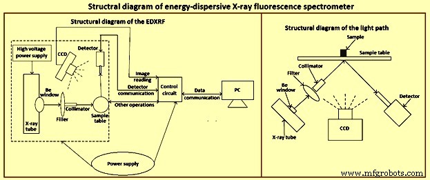
Fig 1 Structureel diagram van EDXRF-spectrometer
Elektromagnetische straling
Elektromagnetische straling is een energievorm die zich door de ruimte kan voortplanten en kan interageren met atomen en moleculen om hun energietoestand te veranderen. Beide eigenschappen zijn belangrijk voor spectroscopie. Elektromagnetische straling vertoont gedrag waarvoor twee theorieën nodig zijn om te verklaren. De golftheorie beschrijft het gedrag van elektromagnetische straling, zoals breking, reflectie, diffractie en verstrooiing. Straling wordt gedefinieerd als een energievorm die bestaat uit twee orthogonale golven, elk met dezelfde frequentie en golflengte. De ene is een oscillerend elektrisch veld en de andere een oscillerend magnetisch veld, waardoor de term elektromagnetische straling wordt geproduceerd.
In een vacuüm is de voortplantingssnelheid van de golf door de ruimte de lichtsnelheid (c =3 × 10 tot de macht 10 cm/s). Dit leidt tot een belangrijke fundamentele relatie weergegeven door de vergelijking w.v =c. Deze uitdrukking stelt dat het product van de golflengte (w) van elektromagnetische straling en de frequentie (v) gelijk is aan de snelheid. De golflengte van elektromagnetische straling varieert over vele ordes van grootte. Radiogolven in de normale AM-omroepband hebben bijvoorbeeld golflengten van enkele honderden meters en ultraviolette golflengten liggen in het bereik van 10 nm tot 100 nm (nanometer). Daarentegen variëren röntgenstralen die nuttig zijn bij spectroscopie van 0,01 nm tot 10 nm (figuur 2).
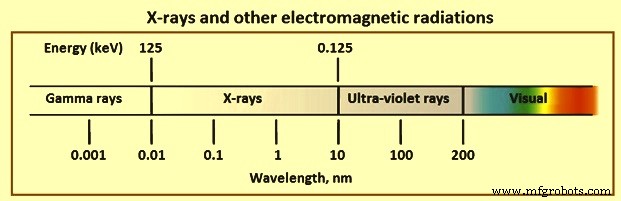
Fig 2 Röntgenstraling en andere elektromagnetische straling
Voor golflengte-dispersieve spectrometrie is het vaak handiger om golflengte-eenheden te gebruiken, maar voor energie-dispersieve röntgenspectrometrie (EDS) is de energiebeschrijving handiger. De interconversie is echter eenvoudig.
Verschillende normaal gebruikte beschrijvingen van de kenmerken van röntgenstralen zijn significant. De juiste betekenis van de intensiteit van elektromagnetische straling is de energie per oppervlakte-eenheid per tijdseenheid; als intensiteit wordt echter vaak het aantal tellingen per tijdseenheid van de detector gebruikt. Omdat het gebied het actieve gebied van de gebruikte detector is en tijd een instelbare parameter is, is het gebruik van tellingen een praktische beschrijving van de röntgenintensiteit. De termen harde of zachte röntgenstralen worden vaak gebruikt om onderscheid te maken tussen röntgenstralen met respectievelijk korte (0,01 nm tot 0,1 nm) en lange (0,1 nm tot 1 nm) golflengten. Röntgenstraling valt in het hoogenergetische gebied van het elektromagnetische spectrum.
Röntgenstraling
Röntgenstralen worden gegenereerd door de verstoring van de elektronenorbitalen van atomen. Dit kan op verschillende manieren worden gedaan, waarbij de meest voorkomende het bombarderen van een doelelement met hoogenergetische elektronen, röntgenstralen of versnelde geladen deeltjes is. De eerste twee worden vaak direct of indirect gebruikt in röntgenspectrometrie. Elektronenbombardement resulteert in een continuüm van röntgenstralingsenergieën en straling die kenmerkend is voor het doelelement. Beide soorten straling komen voor bij röntgenspectrometrie.
Continu – Emissie van röntgenstraling met een vloeiende, continue functie van intensiteit ten opzichte van energie wordt continuüm- of remstrahlung-straling genoemd. Een röntgencontinuüm kan op verschillende manieren worden gegenereerd. De meest bruikbare is echter de elektronenbundel die wordt gebruikt om een doel in een röntgenbuis te bombarderen. Het continuüm wordt gegenereerd als gevolg van de progressieve vertraging van hoogenergetische elektronen die op een doel botsen, wat een verdeling is van orbitale elektronen met verschillende energieën. Terwijl de botsende elektronen interageren met de gebonden orbitale elektronen, wordt een deel van hun kinetische energie omgezet in straling. De hoeveelheid die wordt omgezet, hangt af van de bindingsenergie van het betrokken elektron. Daarom bestaat er een enigszins statistische waarschijnlijkheid over hoeveel energie er wordt omgezet bij elke interactie.
De kans dat een botsend elektron een interactie aangaat met een orbitaal elektron van het doelelement neemt toe met het atoomnummer van het element, dus de intensiteit van de continue emissie neemt toe met het atoomnummer van het doelelement. Verder neemt de waarschijnlijkheid van een interactie toe met het aantal elektronen per tijdseenheid in de bundel, of flux. Daarom neemt de intensiteit van het continuüm toe met de stroom van de elektronenbundel, uitgedrukt in milli-ampère. Bovendien neemt het vermogen van de botsende elektronen om te interageren met strak gebonden elektronen van het doelelement toe met de kinetische energie van de bombarderende elektronen. Omdat de kinetische energie van de elektronen in de bundel toeneemt met het versnellingspotentieel, neemt de geïntegreerde intensiteit van het continuüm toe met het elektronenversnellingspotentieel, uitgedrukt in kilovolt. Ten slotte is de maximale energie die wordt gemanifesteerd als röntgenfotonen gelijk aan de kinetische energie van het botsende elektron, wat op zijn beurt verband houdt met het versnellingspotentieel. De energie van de maximale intensiteit in het continuüm ligt rond tweederde van de maximaal uitgestraalde energie. Verder is er de absorptie van röntgenstralen in het doelmateriaal of absorptie door materialen die worden gebruikt voor vensters in de röntgenbuis en detectoren. Daarom kan enige wijziging van de intensiteitsverdeling optreden, vooral bij lage röntgenenergieën.
Kenmerkende emissie – De meeste elektronen die op een doel botsen, interageren met de orbitale elektronen van het doelelement in niet-specifieke interacties en resulteren in weinig of geen verstoring van de binnenste orbitale elektronen. Sommige interacties resulteren echter in het uitwerpen van elektronen uit deze orbitalen. De resulterende vacatures, of gaten, vertegenwoordigen onstabiele toestanden met hoge energie. Als de orbitale vacatures zich in de binnenste schillen bevinden, vallen elektronen uit de buitenste schillen in cascade om ze te vullen en dit resulteert in een lagere energie en een stabielere toestand. De energie die vrijkomt bij het proces kan zich manifesteren als röntgenstralen. Elk van de overgangen die kunnen optreden, leidt tot de emissie van scherpe röntgenlijnen die kenmerkend zijn voor het doelelement en de betreffende overgang. Deze karakteristieke stralingslijnen worden uitgezonden met het continuüm.
Röntgenopname
Röntgenstralen die invallen op een monster ondergaan twee belangrijke interacties met de elementen van het monster:absorptie en verstrooiing. Absorptie van de straling kan plaatsvinden door specifieke interacties die aanzienlijk zijn in monsterexcitatie in röntgenspectrometrie of door meer algemene interacties die de uitgezonden röntgenstralingsintensiteit van het monster beïnvloeden. Verstrooiing van röntgenstralen leidt tot achtergrondintensiteit in de waargenomen spectra.
Massa-absorptie – Wanneer een röntgenstraal door een materiaal gaat, kunnen de fotonen (elektromagnetische velden) op niet-specifieke manieren interageren met elektronen in de orbitalen van de doelelementen, waardoor de intensiteit van de röntgenstraal wordt verminderd. De interacties kunnen leiden tot foto-elektrische uitstoot van elektronen of verstrooiing van de röntgenstraal. In beide gevallen wordt het totale resultaat vaak beschreven in termen van een exponentiële afname in intensiteit met de weglengte van het absorberende materiaal. De massaabsorptiecoëfficiënt is kenmerkend voor een bepaald element bij gespecificeerde energieën van röntgenstraling. De waarde ervan varieert met de golflengte van de röntgenstraling en het atoomnummer van het doelelement.
Het foto-elektrische effect is het belangrijkste proces dat leidt tot absorptie van röntgenstralen wanneer ze door materie gaan. Het foto-elektrisch effect is de uitstoot van elektronen uit de orbitalen van elementen in het röntgendoel. Dit proces levert vaak de belangrijkste bijdrage aan de absorptie van röntgenstralen en is de wijze van excitatie van de röntgenspectra die worden uitgezonden door elementen in monsters. Voornamelijk als gevolg van het foto-elektrische proces neemt de massaabsorptiecoëfficiënt gestaag af met toenemende energie van de invallende röntgenstraling. De absorptie versus energiecurve voor een bepaald element heeft scherpe discontinuïteiten. Deze zijn het resultaat van karakteristieke energieën waarbij het foto-elektrische proces bijzonder efficiënt is.
Verstrooiing – Wanneer röntgenfotonen een verzameling atomen raken, kunnen de fotonen een interactie aangaan met elektronen van de doelelementen om te resulteren in de verstrooiing van de röntgenfotonen, zoals geïllustreerd in figuur 3. Verstrooiing van röntgenstralen van het monster is de belangrijkste bron van achtergrondsignaal in de spectra verkregen in röntgenspectrometrie. De verstrooiing van röntgenstralen wordt voornamelijk veroorzaakt door buitenste, zwak vastgehouden elektronen van de elementen. Als de botsingen elastisch zijn, treedt verstrooiing op zonder verlies van energie en staat bekend als Rayleigh-verstrooiing. Als het inelastisch is, verliest het röntgenfoton energie om de uitwerping van een elektron te veroorzaken, en de verstrooiing is onsamenhangend. Het pad van het röntgenfoton wordt afgebogen en het foton heeft een energieverlies of een langere golflengte. Dit is Compton scatter.
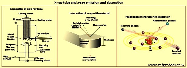
Fig 3 Röntgenbuis en röntgenstraling en absorptie
Scatter beïnvloedt röntgenspectrometrie op twee manieren. Ten eerste neemt de totale hoeveelheid verstrooide straling toe met het atoomnummer vanwege het grotere aantal elektronen. Monsters met matrices met een laag atoomnummer vertonen echter een grotere waargenomen verstrooiing vanwege verminderde zelfabsorptie door het monster. Ten tweede neemt de verhouding van 'Compton-tot-Rayleigh'-verstrooiingsintensiteit toe naarmate het atoomnummer van de monstermatrix afneemt. Het energieverlies dat gepaard gaat met Compton-verstrooiing resulteert in een voorspelbare verandering in de golflengte van de straling.
Relaties tussen elementen en röntgenstralen
De verschillende relaties tussen elementen en röntgenstralen worden getoond in figuur 4.
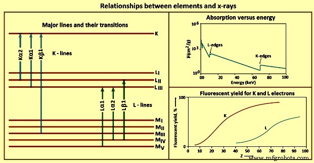
Fig 4 Relaties tussen elementen en röntgenstralen
Absorptie – Röntgenfotonen kunnen interageren met orbitale elektronen van elementen die moeten worden geabsorbeerd of verstrooid. De relatie tussen absorptie en het atoomnummer van het element is belangrijk bij het selecteren van optimale bedrijfsomstandigheden voor röntgenspectrometrie.
Massaabsorptiecoëfficiënten verschillen voor een bepaald element of stof voor elk element of elke stof bij een bepaalde energie van röntgenstraling en bij elke energie van röntgenstraling. Vanwege de grotere kans op interactie met orbitale elektronen, neemt de massaabsorptiecoëfficiënt toe met het atoomnummer van het element van het doelmateriaal. Bij een bepaald atoomnummer neemt de massaabsorptiecoëfficiënt af met de golflengte van de röntgenstraling. Deze zijn het resultaat van specifieke energieën die nodig zijn voor de foto-elektrische uitstoot van elektronen uit de verschillende orbitalen van het atoom en zijn kenmerkend voor het element.
Absorptieranden zijn discontinuïteiten of kritische punten in de grafiek van massaabsorptie versus golflengte of energie van invallende röntgenstraling. Absorptierandenergie is de exacte hoeveelheid die een elektron uit een baan van een element foto-ejecteert. Hoe lager het hoofdkwantumgetal, des te hoger is de energie die in acht wordt genomen om een elektron uit die schil te werpen. De golflengte van een röntgenstraal die een L-elektron kan uitstoten is langer (met minder energie) dan nodig is om een elektron uit de K-schil te werpen. Dat wil zeggen, de K-absorptierandenergie is groter dan de L-absorptierandenergie voor een bepaald element.
Emissie – Het foto-elektrisch effect is een röntgenabsorptiemechanisme waardoor onstabiele toestanden in de elektronenorbitalen van atomen worden gecreëerd. Zodra de vacatures in de binnenste orbitalen zijn gevormd, kan relaxatie naar de stabiele grondtoestand optreden door de emissie van röntgenstralen die kenmerkend zijn voor het geëxciteerde element. De energie van de 1s elektron is afgeschermd van de toestand van de valentie-elektronen, zodat de absorptie-randenergie en de energie van de uitgezonden röntgenstralen in wezen onafhankelijk zijn van de oxidatietoestand en binding van het atoom.
K-lijnen – Zodra het foto-elektrisch effect een leegte in de K-schil creëert, ontspant de aangeslagen toestand door de leegte te vullen met een elektron uit een buitenste orbitaal. Alleen bepaalde overgangen zijn toegestaan vanwege kwantummechanische regels die selectieregels worden genoemd. De overgangen die de selectieregels volgen, worden toegestane (diagram) lijnen genoemd, die welke dat niet zijn, worden verboden genoemd, en die welke resulteren in atomen met twee of meer vacatures in de binnenste orbitalen op het moment van de emissie worden satelliet (niet-diagram) genoemd. ) lijnen. Het aantal K-lijnen, en de exacte die voor een element wordt waargenomen, hangt gedeeltelijk af van het aantal gevulde orbitalen.
L-lijnen – Aangezien het praktische energiebereik voor de meeste WDXRF-röntgenspectrometers 0 keV tot 100 keV en 0 keV tot 40 keV voor EDXRF-spectrometers is, moet het gebruik van andere emissielijnen dan de K-lijnen worden overwogen. Voor een bepaald element worden L-lijnen geëxciteerd met lagere röntgenstralingsenergie dan K-lijnen. Het gebruik van L-lijnen is vooral waardevol voor elementen met atoomnummers hoger dan ongeveer 45.
M lijnen –M-lijnen vinden beperkte toepassing in routinematige röntgenspectrometrie. De lijnen worden niet waargenomen voor elementen met atoomnummers lager dan ongeveer 57, en wanneer ze worden waargenomen, zijn de overgangsenergieën laag. Het enige praktische gebruik van deze lijnen is voor elementen als thorium, protactinium en uranium. Ze mogen alleen in deze gevallen worden gebruikt om interferentie met L-lijnen van andere elementen in het monster te voorkomen.
Fluorescerende opbrengst - Een elektron wordt door het foto-elektrische proces uit een atomaire orbitaal uitgestoten met twee mogelijke resultaten, ofwel röntgenfotonenemissie of secundaire (Auger) elektronenejectie. Een van deze gebeurtenissen vindt plaats voor elk aangeslagen atoom, maar niet voor beide. Daarom concurreert secundaire elektronenproductie met röntgenfotonenemissie van geëxciteerde atomen in een monster. De fractie van de aangeslagen atomen die röntgenstraling uitzendt, wordt de fluorescentieopbrengst genoemd. Deze waarde is een eigenschap van het element en de röntgenlijn in kwestie. Elementen met een laag atoomnummer hebben ook een lage fluorescerende opbrengst. In combinatie met de hoge massaabsorptiecoëfficiënten die röntgenstraling met lage energie laat zien, is de detectie en bepaling van elementen met een laag atoomnummer door röntgenspectrometrie een uitdaging.
Effecten tussen elementen – Voor overgangen in röntgenspectrometrie heeft geen enkele emissielijn voor een bepaalde reeks (K, L, M) van een element een energie gelijk aan of groter dan de absorptieflank voor die reeks. Een belangrijk resultaat is dat de röntgenstraling die door een element wordt uitgezonden, geen elektronen kan uitstoten uit dezelfde baan van andere atomen van dat element. Een monster dat is samengesteld uit een mengsel van elementen, kan echter interacties vertonen die vaak effecten tussen elementen worden genoemd. Dergelijke interacties van elementen binnen een steekproef vereisen vaak speciale gegevensanalyse.
WDXRF-spectrometers
Röntgenspectrometrische instrumentatie die in de jaren vijftig commercieel werd geïntroduceerd, staat bekend als golflengte-dispersief, wat aanduidt dat de straling die door het monster wordt uitgezonden, wordt gecollimeerd met behulp van een Soller-collimator en vervolgens op een analyserend kristal valt. Het kristal buigt de straling in verschillende mate af volgens de wet van Bragg en afhankelijk van de golflengte of energie van de röntgenstraling. Deze hoekspreiding van de straling maakt sequentiële of gelijktijdige detectie mogelijk van röntgenstralen die worden uitgezonden door elementen in het monster.
Gelijktijdige instrumenten bevatten normaal gesproken meerdere sets analysekristallen en detectoren; één wordt aangepast voor elke gewenste analyt in het monster. Hoewel duur, zijn deze instrumenten efficiënt voor routinematige bepaling van vooraf geselecteerde elementen, maar ze kunnen niet gemakkelijk worden geconverteerd om andere elementen te bepalen dan degene die bij installatie zijn geselecteerd.
Vaker zijn sequentiële instrumenten die een mechanisch systeem bevatten dat bekend staat als een goniometer en die de hoek tussen het monster varieert, het kristal analyseert en de detector. Op deze manier kan de gewenste golflengte van röntgenstraling worden geselecteerd door beweging van de goniometer. Sequentiële WDXRF-spectrometers kunnen computergestuurd worden voor automatische bepaling van veel elementen. Kwantitatieve toepassingen van geautomatiseerde WDXRF-spectrometers zijn efficiënt, omdat het instrument kan worden geprogrammeerd om naar de juiste hoeken te gaan voor gewenste bepalingen. Kwalitatieve toepassingen zijn echter minder efficiënt omdat het spectrum langzaam moet worden gescand.
Röntgenbuizen – Er kunnen verschillende energiebronnen worden gebruikt om de geëxciteerde elektronische toestanden te creëren in de atomen van elementen die röntgenstraling produceren. Hiertoe behoren elektronenbundels, bundels van geladen deeltjes en röntgenstraling. Elektronenbundels worden op het monster gericht in technieken als scanning-elektronenmicroscopie (SEM) en elektronenmicroprobe-analyse. Het gebruik van een elektronenbundel heeft echter een hoog vacuüm nodig om energieverliezen van het elektron te voorkomen. Röntgenspectrometrie wordt het best gebruikt als een veelzijdig analytisch hulpmiddel in plaats van als een speciaal hulpmiddel. Veel monsters zijn niet geschikt voor een hoog vacuüm of zijn niet-geleiders, die problemen met elektrisch opladen veroorzaken wanneer ze zich onder een elektronenbundel bevinden. Daarom is deze energiebron niet praktisch voor röntgenspectrometrie.
Radioactieve isotopen die röntgenstraling uitzenden, zijn een andere mogelijkheid voor excitatie van atomen om röntgenstraling uit te zenden. De röntgenstraalstroom van isotopenbronnen die veilig in een laboratorium kan worden gehanteerd, is echter te zwak voor praktisch gebruik. Omdat deze bronnen normaal gesproken slechts een paar smalle röntgenlijnen uitzenden, zijn er meerdere nodig om veel elementen efficiënt te exciteren. De meest praktische energiebron voor röntgenspectrometrie is een röntgenbuis (Fig 3).
WDXRF-spectrometer heeft efficiënte high-power excitatie nodig om goed te presteren. Daarom is stabiliteit en betrouwbaarheid van de röntgenbuis belangrijk. Alle componenten bevinden zich in een hoog vacuüm. Een gloeidraad wordt verwarmd door een gloeispanning van 6 V tot 14 V. De verwarmde gloeidraad zendt thermisch elektronen uit. De stroom van elektronen die tussen de gloeidraad en de doelanode stroomt, moet sterk worden gereguleerd en gecontroleerd. Deze elektronenstroom is elektrische stroom en wordt normaal gemeten in milli-ampère. De buisstroom wordt vaak de mA genoemd.
Tussen de gloeidraad (kathode) en de doelanode wordt een potentiaal van enkele kilovolts aangelegd, die als versnellingspotentiaal voor de elektronen dient. Deze spanning wordt normaal gemeten in kilovolt. De anode is normaal gesproken van koper en het doeloppervlak is geplateerd met zeer zuivere afzettingen van elementen zoals rhodium, zilver, chroom, molybdeen of wolfraam. Röntgenbuizen die worden gebruikt voor WDXRF-spectrometrie werken bij 2 kW tot 3 kW. Veel van dit vermogen verdwijnt als warmte, en voorzieningen voor waterkoeling van de röntgenbuis zijn noodzakelijk. De voedingen en bijbehorende elektronica voor deze röntgenbuizen zijn groot. De elektronen raken het doelwit met een maximale kinetische energie die gelijk is aan de aangelegde buispotentiaal. Als de kinetische energie van het elektron de absorptie-randenergie overschrijdt die overeenkomt met de uitstoot van een binnenste orbitaal elektron uit atomen van het doelmateriaal, zendt de buis röntgenlijnen uit die kenmerkend zijn voor het doelelement. Interactie van de elektronen in de bundel met elektronen van het doelelement leidt ook tot emissie van een continuüm. Het gebied van het continuüm en de golflengte van maximale intensiteit zijn afhankelijk van de potentiaal, stroom en anodesamenstelling.
Kristalen analyseren – Röntgenstralen die door de röntgenbuis worden uitgezonden, worden op het monster gericht. In de meeste röntgenspectrometers wordt het monster boven de röntgenbuis geplaatst in wat bekend staat als omgekeerde optica. Dit vergemakkelijkt het positioneren van het oppervlak van een vloeistof met behulp van het bodemoppervlak in plaats van de bovenkant. De röntgenstraling die door het monster wordt uitgezonden, wordt gecollimeerd en valt op het oppervlak van een analyserend kristal, dat de straling verspreidt. De parallelle bundel polychromatische röntgenstraling van het monster wordt afgebogen vanuit verschillende roostervlakken in het kristal. Versterking treedt op als de extra afstand die de straling moet afleggen door diffractie van verschillende roostervlakken gelijk is aan een geheel veelvoud van de golflengte. Als dit niet het geval is, vindt destructieve interferentie plaats. De wet van Bragg maakt berekening mogelijk van de hoek waaronder een golflengte moet worden geselecteerd voor het analyserende kristal.
Detectoren – Detectors en bijbehorende elektronica in de WDXRF-spectrometer detecteren röntgenstralen die door het analyserende kristal zijn afgebogen en verwerpen ongewenste signalen zoals diffractie van hogere of lagere orde door het analyserende kristal of detectorruis. Twee detectoren worden normaal gesproken in tandem geplaatst. De eerste is een gasgevulde of stromende proportionele detector. Deze detectoren bestaan uit een draad die geïsoleerd is van de behuizing. Dunne polymeervensters aan de voor- en achterkant van de behuizing laten röntgenstraling binnen en mogelijk naar buiten. Tussen de draad en de behuizing wordt een voorspanningspotentiaal van een paar honderd volt aangelegd.
Hoewel er veel gassen kunnen worden gebruikt, is het typische gas P-10, een mengsel van 90% argon (Ar) en 10% methaan. Wanneer röntgenstralen de detector binnenkomen, wordt het argon geïoniseerd om veel Ar+-e-paren te produceren. De anodedraad verzamelt de elektronen en de elektronen aan de kathodische wanden van de behuizing neutraliseren de Ar+-ionen. Het resultaat is een stroompuls voor elk röntgenfoton dat de detector binnenkomt. De met P-10 gevulde proportionele detectoren zijn het meest efficiënt voor het detecteren van röntgenfotonen met een energie van minder dan ongeveer 8 keV (golflengten hoger dan ongeveer 0,15 nm). Meer energetische röntgenstraling heeft de neiging om door de proportionele detector te gaan.
Een tweede detector die zich vaak achter de proportionele teller bevindt, is normaal gesproken een scintillatiedetector. Deze detector bestaat uit een met thallium gedoteerd natriumjodidekristal [NaI(Tl)], dat een uitbarsting van blauw (410 nm) licht uitzendt wanneer het wordt geraakt door een röntgenfoton. Het kristal is gemonteerd op een fotomultiplicatorbuis die de lichtpulsen detecteert. Het aantal geproduceerde lichtfotonen is evenredig met de energie van het invallende röntgenfoton. Na elektronische verwerking wordt de scintillatieburst omgezet in een spanningspuls die in amplitude evenredig is met de röntgenfotonenergie. Deze twee detectoren kunnen onafhankelijk of gelijktijdig worden bediend. Bij gelijktijdige werking moeten de bedrijfspotentiaal van de detector en de uitgangsversterking zo worden aangepast dat een röntgenfoton met een bepaalde energie dezelfde pulshoogtespanning van beide detectoren produceert. Beide detectortypes hebben ongeveer 1 microseconde nodig om te herstellen tussen pulsen. Sommige tellingen kunnen verloren gaan bij invallende fotonensnelheden van meer dan ongeveer 30.000/sec. Pulshoogtediscriminatie van de röntgenpulsen van de detector(en) verwerpt röntgenstralen van hogere of lagere orde die door het analyserende kristal worden afgebogen.
Basisprincipes – Wanneer een monster wordt overwogen en het analyt-element is geselecteerd, is de eerste beslissing om de emissielijn te selecteren. Bij afwezigheid van specifieke interferenties wordt meestal de meest energetische lijn gebruikt. Voor elementen met atoomnummers van minder dan ongeveer 75 is dit normaal gesproken de K-lijn, aangezien veel WDXRF-spectrometers kunnen werken tot 100 kV-potentialen voor de röntgenbuizen. Indien mogelijk wordt een röntgenbuis gekozen die karakteristieke lijnen uitzendt bij energieën net boven de absorptierand voor de lijn die wordt gebruikt voor het analyt-element. Als een dergelijke buis niet beschikbaar is, moet de excitatie worden bereikt door gebruik te maken van het continuüm voor een beschikbare röntgenbuis.
De potentiaal van de röntgenbuis moet worden ingesteld op ongeveer 1,5 keer de absorptierandenergie of hoger. De detector moet worden geselecteerd op basis van het te gebruiken golflengtegebied. De proportionele teller moet worden gebruikt voor röntgenstralen langer dan ongeveer 0,6 nm, de scintillatiedetector voor golflengten korter dan ongeveer 0,2 nm en beide voor het overlappende gebied van 0,2 nm tot 0,6 nm. Er moet een analysekristal worden gekozen waarmee de gewenste golflengte kan worden gedetecteerd. De meeste parameterselecties worden uitgevoerd via computerbesturing.
Energie-dispersieve röntgenspectrometers
Het gebruik van een goniometer in WDXRF-röntgenspectrometers is gebaseerd op de vereiste om de röntgenstralen die door verschillende elementen in een monster worden uitgezonden, op te lossen in componenten. Het gebruik van een dispersieapparaat is gebruikelijk in veel soorten spectroscopie om deze taak te volbrengen. Instrumenten zonder de mechanische componenten zijn wenselijk als een adequate resolutie kan worden bereikt. De ontwikkeling van door lithium aangedreven siliciumdetectoren en hun toepassing op röntgendetectie in het midden van de jaren zestig leidde tot een gebied van spectroscopische analyse dat bekend werd als EDXRF-spectrometrie.
Röntgenbuizen die in WDXRF-spectrometers worden gebruikt, hebben een vermogen van 2 kW tot 3 kW en moeten watergekoeld worden. Die welke in EDXRF-spectrometers worden gebruikt, werken met een veel lager vermogen en zijn meestal luchtgekoeld. Typische buizen variëren van 9 W tot 100 W. Er zijn verschillende anodematerialen beschikbaar en elke fabrikant van röntgenspectrometers biedt speciale röntgenbuiskenmerken. Na vele proeven met buisontwerp, blijven de meeste echter bij het traditionele 'zijraam'-ontwerp, hoewel het veel kleiner is dan die gebruikt in WDXRF-spectrometers. Een belangrijke factor bij het ontwerp van de buis en de bijbehorende voeding is de stabiliteit van de buis en het voltage.
Een alternatief voor de directe röntgenbuisexcitatie is het gebruik van secundaire doelexcitatie. In deze modus wordt een röntgenbuis gebruikt om een secundair doel te bestralen, waarvan de karakteristieke röntgenfluorescentie op zijn beurt wordt gebruikt om de röntgenstraling van het monster te exciteren. Vanwege het aanzienlijke efficiëntieverlies bij gebruik van een secundair doel, zijn röntgenbuizen met een hoger wattage nodig dan vereist voor directe excitatie.
Secundaire-target-excitatie biedt soms aanzienlijke voordelen. Om bijvoorbeeld de lage concentratieniveaus van vanadium en chroom in een ijzermonster te bepalen, kunnen deze elementen worden geëxciteerd met een secundair ijzerdoel zonder excitatie van het ijzer in het monster. Bij directe-buisexcitatie is dit moeilijk. Er zijn verschillende secundaire doelen nodig om een breed scala aan elementen te bestrijken. Het gebruik van secundaire doelexcitatie is ondersteund als een bron van monochromatische straling voor excitatie. Het belang van dit voordeel is dat veel van de computerprogramma's met fundamentele parameters, die worden gebruikt om intensiteiten rechtstreeks uit de basisröntgenvergelijkingen te berekenen, monochromatische excitatiestraling nodig hebben.
In de praktijk benadert secundaire excitatie alleen de ideale monochromatische straling. Directe-buisexcitatie met geschikte primaire filters presteert goed in vergelijking met secundaire doeltechnieken. Daarom blijft directe excitatie van röntgenbuizen het meest praktisch voor het grootste aantal toepassingen van energiedispersieve spectrometrie (EDS). De belangrijkste kracht van de EDS-techniek ligt in de gelijktijdige multi-element analysemogelijkheden. Although special cases occur in which selective excitation is desirable, this frequently can be accomplished with intelligent use of an appropriate x-ray tube and filter. Any fundamental design features which limit the simultaneous multi-element capability diminish the advantage of the EDXRF spectrometer.
Since direct x-ray tube excitation is the most common method used in EDS, there are factors which govern the selection of an x-ray tube. In wavelength-dispersive techniques, several x-ray tubes are normally available for the spectrometer. These can be changed for different applications. This is not normally the case with EDS-systems, since many WDXRF spectrometer has few if any choices of primary filters. In wavelength-dispersive techniques, it is customary to attempt to excite the desired element by the characteristic emission lines of the tube anode material, but the continuum is used more efficiently in EDXRF spectrometers. The use of EDXRF spectrometers has been enhanced by computer control of tube current and voltage and selection of the primary filter. Selection and efficient use of a single x-ray tube is important in the configuration of an EDXRF system.
Characteristic lines emitted by an x-ray tube have much larger intensity at their maxima than the continuous radiation emitted. These lines are to be used for excitation whenever possible. In addition, use of a primary filter between the x-ray tube and the sample can effectively approximate monochromatic radiation impinging on the sample from these characteristic lines. EDXRF spectrometers normally offer various x-ray tube anode materials. For selecting the x-ray tube anode material, the applications most likely to be encountered are to be considered.
The principal concern is to select an anode which has characteristic lines close to, but always higher, in energy than the absorption-edge energies to be encountered. None of the characteristic lines are to create spectral interference with elements to be determined. This includes consideration of such details as the Compton scatter peak for the characteristic lines. In addition, it is difficult to perform determinations of the element of the anode material. This is especially true with samples having low concentrations of that element.
Rhodium is a favourable tube anode material for general-purpose use. The characteristic lines of this element are efficient for the excitation of elements with absorption edges to around 15 keV. The excitation efficiency for the K lines of the transition elements is low. However, the continuum can be used efficiently in this region. Rhodium also has characteristic L lines at around 2.7 keV to 3.0 keV. These are efficient for the excitation of the K lines of low atomic number elements, such as aluminum, silicon, phosphorus, and sulphur. However, in these cases, a silver anode is preferable because of the Compton scatter radiation from the rhodium lines. The characteristic lines and the continuum from the x-ray tube can be used for excitation.
Although the elements of many samples can be excited effectively using a combination of the characteristic x-ray lines from the tube anode element and the continuum, more monochromatic radiation is sometimes desired. One such situation involves enhancing the use of fundamental-parameter computations which permit quantitative determination of elements without the need for several concentration standards. A more frequent situation is the need to reduce the background in the spectrum energy range to be used in the analysis. Use of primary filters placed between the x-ray tube and the sample can be effective in these cases and are normally incorporated under computer control in commercial spectrometers.
The object is to filter the primary radiation from the x-ray tube and selectively pass the characteristic lines of the anode element. This is accomplished using a filter made of the same element as the tube anode. Since x-rays of a given line (K, L, and so on) of an element are lower in energy than the absorption edge for that element, the photoelectric component of the mass absorption coefficient is small. Such a filter does not efficiently absorb the characteristic line emitted by the x-ray tube. The higher energy x-rays from the continuum are efficient for the photoelectric process in the filter and are highly attenuated by absorption. X-rays of lower energy than the filter material absorption edge are absorbed more efficiently as the energy decreases.
The result is x-radiation striking the sample with an intensity which is largely determined by the characteristic lines of the tube anode and that approximates monochromatic radiation. Increasing the thickness of the filter decreases the total intensity, with further gain in the monochromatic approximation.
Detectors – The selective determination of elements in a mixture using x-ray spectrometry depends upon resolving into separate components the spectral lines emitted by the different elements. This process needs an energy-sorting or wavelength-dispersing device. For the WDXRF spectrometer, this is accomplished by the analyzing crystal, which needs mechanical movement to select each desired wavelength according to Bragg’s law. Optionally, several fixed-crystal channels can be used for simultaneous measurement. In contrast, EDS is based on the ability of the detector to create signals proportional to the x-ray photon energy. Hence, mechanical devices, such as analyzing crystals, are not needed.
Several types of detectors have been used, including silicon, germanium, and mercuric iodide. The solid-state, lithium-drifted silicon detector [Si(Li)] was developed and applied to x-ray detection in the 1960s. By the early 1970s, this detector was firmly established in the field of x-ray spectrometry and was applied as an x-ray detection system for SEM and x-ray spectrometry. The Si(Li) detector provides excellent resolution. It can be considered as a layered structure. Under reversed bias of around 600 V, the active region acts as an insulator with an electric-field gradient throughout its volume.
When an x-ray photon enters the active region of the detector, photo ionization occurs with an electron-hole pair created for each 3.8 eV of photon energy. Ideally, the detector is to completely collect the charge created by each photon entry and result in a response for only that energy. Some background counts appear because of energy loss in the detector. Although these are kept to a minimum by engineering, incomplete charge collection in the detector contributes to background counts. From 1 keV to 20 keV, an important region in x-ray spectrometry, silicon detectors are efficient for conversion of x-ray photon energy into charge.
Analyzer systems – The x-ray spectrum of the sample is obtained by processing the energy distribution of x-ray photons which enter the detector. One x-ray photon entering the detector causes photo-ionization and produces a charge proportional to the photon energy. Several electrical sequences are to take place before this charge can be converted to a data point in the spectrum. A detailed knowledge of the electronics is not necessary, although an understanding of their functions is important. Upon entering the Si(Li) detector, an x-ray photon is converted into an electrical charge which is coupled to a field effect transistor (FET). The FET and the electronics comprising the preamplifier produce an output proportional to the energy of the x-ray photon. Using a pulsed optical preamplifier, this output is in the form of a step signal. Since photons vary in energy and number per unit time, the output signal, due to successive photons being emitted by a multi-element sample, resembles a staircase with various step heights and time spacing. When the output reaches a determined level, the detector and the FET circuitry reset to their starting level, and the process is repeated.
The preamplifier output is coupled to a pulse processor which amplifies and shapes the signal into a form acceptable for conversion to a digital form by an analog-to-digital converter (ADC). Amplification is necessary to match the analog signal to the full-scale range of the ADC. This process involves the energy calibration of the spectrometer. Drift in the gain and/or offset (zero) of the amplification results in errors in the energy assigned to the x-ray photons producing the signal. Hence, these calibrations are to be as stable as possible, and calibration is to be routinely checked.
The energy calibration is important for qualitative identification of the elements and for precise quantitative results when using spectrum-fitting programs. The amplifier provides gain and zero controls for calibrations. Normal operation in x-ray spectrometry is to set the time on the system clock to be used to acquire the spectrum. The processing of the pulses is not instantaneous. At high count rates, the time needed can become significant. When a pulse is detected and processing initiated, the clock is ‘stopped’ until the system is ready to process a new photon. The length of time the clock is off is called dead time; the time the clock is on is called live time. Their total is real time. The system monitors live time. If the spectrometer is operated with a 50 % dead time, the real time is twice the live time.
Processing of the pulse created by a photon is to be complete before another pulse occurs. A pulse pile-up rejector circuit blocks a pulse if it is received too soon. Once activated, the pulse pile-up rejector prevents the new signal from being processed if a second x-ray enters the detector before a prior pulse is fully processed. If analysis of the prior pulse had not yet been complete, it is also to be blocked from further processing. If this blockage is not performed, pulse pile-up occurs, resulting in an artifact which appears at energies equal to the sum of the photon energy of the first and second photons to enter the detector. These are frequently called sum peaks.
Despite pulse pile-up rejection circuitry, sum peaks are observed for intense peaks in the spectrum. This is the result of two photons entering the detector simultaneously or within a time difference faster than the fast discriminator can act. Sum peaks can be observed at twice the energy of an intense peak and / or at the sum of the energies of two intense peaks in the spectrum. Sum peaks decrease rapidly in intensity with count rate. The importance of electronic pulse-processing components to system performance is easily overlooked in EDS. However, stability, linearity, and proper calibration of these components are important for the use of the spectrometer.
EDXRF spectrometers require a dedicated computer system for data acquisition. Early spectrometers were heavy, unwieldy units which used hard-wired multichannel analyzers which could acquire data, but could do little to process it. Current spectrometer and data systems based on microprocessor technology are available as table-top units.
Fundamentals of operation – The simultaneous multi-element capability of EDS complicates the selection of optimum conditions because of the factors to be considered for each element. The compromises in spectroscopy are to be made, but the initial selection of instrument operating conditions can follow a logical sequence of decisions.
Qualitative analysis needs similar procedures, normally with less stringent requirements. Once a sample is received for analysis and the elements to be determined by x-ray spectrometry are identified, the next decision is to ascertain which x-ray lines are to be used for the determinations. As a general rule, K lines are used upto a K absorption-edge energy a few keV below the characteristic line of the x-ray tube anode element. The continuum can be used for excitation if the voltage to the x-ray tube is set sufficiently high to place the continuum maximum at energy higher than the absorption edge and if a back-ground filter is used. In these cases, K absorption-edge energies can be used upto around 66 % of the maximum operating kV of the x-ray tube. However, the observed peaks lie on a continuum background and reduce the signal-to-noise ratio.
For a 50-kV x-ray tube, absorption edges as high as 30 keV can be used if the element is present in sufficient concentration. For a 30-kV rhodium or silver tube, one is restricted essentially to excitation by the characteristic tube lines. This is of no great concern unless there is a special interest in the elements between atomic numbers 41 and 50 (niobium to tin). Elements above atomic number 50 (40 for a 30-kV system) are normally to be determined using the L lines of their x-ray spectra.
To excite all L lines, the incident x-ray photon energy is to exceed the LI absorption edge. For practical use, the energy of the L lines is to be higher than around l keV. For the L line spectra, this needs atomic numbers higher than 30. At such low x-ray energies, absorption of the x-rays and low fluorescent yield in the L emission in this region needs high concentration of the element to be determined and excellent sample preparation. Overlap of the K lines of the low atomic number elements in this region also causes difficulty. For example, the K lines of phosphorus overlap with the L lines of zirconium and the M lines of iridium at around 2 keV. These problems are to be considered, but are to a large degree solved by careful use of processing software.
Once the x-ray spectral lines are selected for determination of the elements, the next step is to decide whether all analyte elements in the sample can be determined with one instrumental setting. Although the multi-element capability of EDS is useful, all elements in every sample cannot be determined with a single set of instrument parameters. Some applications need more than one condition, such as a mixture of low atomic number elements and transition elements. The transition elements are best determined by excitation using the K lines of rhodium or silver and the low atomic number elements with the L lines or a properly adjusted continuum using a background filter. Computer control of instrument parameters facilitates changing the conditions. Whether automatic or manual control is used, all samples are to be analyzed under one set of conditions, then analyzed again using the alternate set. This is preferred over changing conditions between samples.
X-ray tube operating voltage affects the efficiency of excitation of each element in the spectrum and the integrated x-ray photon flux from the tube. The tube current affects the flux only. Hence, once the operating kV has been set, the tube current typically is adjusted until the system is processing counts efficiently. System dead time is to be maintained below, but near, 50 %. The voltage and current settings for the x-ray tube have a sensitive effect on the rate of information acquisition and count distribution among the respective spectral peaks for a given type of sample.
Selection of primary tube filter thickness is important. If the filter is changed, the tube current, and sometimes the voltage, frequently needs resetting since the filter alters the intensity distribution of the x-rays striking the sample. When characteristic tube lines are used for excitation, the filter is normally made from the tube anode element. The intensity of the transmitted x-rays decrease exponentially with increasing filter thickness. It is common to have two or three primary filters made from the tube anode element in the filter holder. The selection is to reflect optimum count rate corresponding with reasonable current and voltage settings. Thicker filters attenuate lower energy radiation more effectively and reduce the excitation efficiency for the element with low absorption coefficients.
The remaining decision is the choice of atmosphere in the sample chamber. If x-rays below around 5 keV are to be implemented, use of a vacuum can be advantageous. Intensity can increase sufficiently to reduce significantly the counting time needed to achieve an adequate number of counts. If the concentration of elements yielding these x-rays is sufficiently high, the vacuum may not be needed. Because of the extra precautions needed in sample criteria and handling, a vacuum path is not to be used unless significant benefit is realized. Similar reasoning applies to the helium atmosphere.
These guidelines are useful for initial selection of operating conditions. The instrumental parameters are interactive, and a change in one parameter needs adjustment of another. For example, selection of a thicker primary filter or a decrease in the tube voltage needs an increase in the tube current.
Sample preparation
The care taken to determine the best method of sample preparation for a given material and careful adherence to that method frequently determine the quality of results obtained. Sample preparation is the single most important step in an analysis, yet it is frequently given the least attention. In most cases, the stability and overall reproducibility of x-ray instrumentation are the least significant factor affecting the precision of analytical measurements. Frequently, the precision of analytical results expected from x-ray spectrometric determinations is expressed in terms of the theoretical statistics of measurement of x-ray intensities.
When replicate samples are prepared and actual standard deviations measured, deviations are found to be larger than those predicted by counting statistics. If precision is poor, any one analytical result can also be poor, since it can differ substantially from the ‘true’ value. The variety of sample types which can be analyzed using x-ray spectrometry necessitates different sample preparation techniques.
Samples are frequently classified as infinitely thick or infinitely thin based on measurement of the attenuation of x-rays. Samples are considered to be infinitely thick if further increase in the thickness yields no increase in observed x-ray intensity. The critical value for infinite thickness depends on the energy of the emitted x-radiation and the mass absorption coefficient of the sample matrix for those x-rays. For pure iron, the critical thickness is around 40 m for iron x-rays.
Although infinitely thin samples afford several advantages, it is rarely feasible to prepare them from routine samples. Many samples fall between these two cases and need extreme care in preparation. In addition to preparation of the sample, precise positioning of the sample in the spectrometer is critical for quantitative determinations.
Solid samples – These are defined as single bulk materials, as opposed to powders, filings, or turnings. Solid samples can frequently be machined to the shape and dimensions of the sample holder. The processing is not to contaminate the sample surface to be used for analysis. In other cases, small parts and pieces are to be analyzed as received. The reproducible positioning of these samples in the spectrometer is critical. It is frequently useful to fashion a wax mould of the part which fits into the sample holder. Using the mould as a positioning aid, other identical samples can be reproducibly placed in the spectrometer.
Samples taken from unfinished bulk material frequently needs surface preparation prior to quantitative analysis. Surface finishing can be done using a polishing wheel, steel wool, or belt grinder, with subsequent polishing using increasingly fine abrasives. Surface roughness less than 100 micrometers is normally sufficient for x-ray energies above around 5 keV, but surface roughness of less than 20 micrometers to 40 micrometers is needed for energies down to around 2 keV. Several precautions are necessary. Alloys of soft metals can smear on the surface as the sample is polished, resulting in a surface coating of the soft metal which yields high x-ray intensities for that element and subsequently high analytical results.
Polishing grooves on the surface of the sample can seriously affect the measured intensity of low-energy x-rays. This can be examined by repetitive measurement of the intensity of a sample after 45 degrees or 90 degrees rotation. Use of a sample spinner reduces this effect. If a sample spinner is not available, the sample is to be placed in the spectrometer such that the incident x-radiation is parallel to the polishing direction.
Powders and briquettes – Powder samples can be received as powders or prepared from pulverized bulk material too inhomogeneous for direct analysis. Typical bulk samples pulverized before analysis are ores, and refractory materials. Powders can be analyzed using the spectrometer, pressed into pellets or briquettes, or fused with a flux, such as lithium tetra borate. The fused product can be reground and pressed or cast as a disk. For precise quantitative determinations, loose powders are rarely acceptable, especially when low-energy x-rays are used. Pressed briquettes are more reliable. However, experience indicates that the best compromise is reground and pressed fusion products. This technique eliminates several problems associated with particle-size effects.
Particle-size effects result from the absorption of the incident and emitted x-rays within an individual particle. If the mass absorption coefficient of the sample matrix is high for the x-radiation used, particles even a few microns in diameter can considerably affect attenuation of the radiation within each particle. If the sample consists of particles of various sizes, or the particle size varies between samples, the resulting x-ray intensities can be difficult to interpret. This problem is compounded by the tendency of a material composed of a mixture of particle sizes to segregate when packed.
Determination of elements using low-energy x-radiation can lead to errors from particle-size effects of as much as 50 %. If the needed speed of analysis prohibits use of fusion techniques, direct determination from packed powders can be considered. The sample is to be ground, if possible, to a particle size below the critical value. The grinding time needed frequently can be ascertained by measuring the intensity from a reference sample at increasing grinding times until no further increase is observed. The lowest energy x-ray to be used in analysis is to be selected for this test.
Briquettes or pressed powders yield better precision than packed powder samples and are relatively simple and economical to prepare. In several cases, only a hydraulic press and a suitable die are needed. In the simplest case, the die diameter is to be the same as the sample holder so that the pressed briquettes fit directly into the holder. The amount of pressure needed to press a briquette which yields maximum intensity depends on the sample matrix, the energy of the x-ray to be used, and the initial particle size of the sample. Hence, prior grinding of the sample to a particle size which is less than 100 micrometers is advisable.
A series of briquettes are to be prepared from a homogeneous powder using increasing pressure. The measured intensity of the x-ray lines to be used in the analysis is plotted versus the briquetting pressure. The measured intensity is to approach a fixed value, perhaps asymptotically. Pressures of 138 MPa to 276 MPa may be needed. For materials which do not cohere to form stable briquettes, a binding agent is needed. Acceptable binding agents include powdered cellulose, detergent powders, starch, stearic acid, boric acid, lithium carbonate, polyvinyl alcohol, and commercial binders.
Briquettes which are not mechanically stable can be improved by pressing them into backing of pre-pressed binder, such as boric acid, or by the use of a die which presses a cup from a binding agent. The sample powder can then be pressed into a briquette supported by the cup. Improved results are frequently achieved if around 0.1 mm to 0.5 mm is removed from the surface of the briquette prior to the measurement.
Fusion of materials – Fusion of materials with a flux can be performed for several reasons. Some refractory materials cannot be dissolved, ground into fine powders, or converted into a suitable homogeneous form for x-ray spectrometric analysis. Other samples can have compositions which lead to severe inter-element effects, and dilution in the flux reduces these. The fused product, cast into a glass button, provides a stable, homogeneous sample well suited for x-ray measurements. The disadvantages of fusion techniques are the time and material costs involved as well as the dilution of the elements which can result in a reduction in x-ray intensity. However, when other methods of sample preparation fail, fusion frequently provides the needed results.
Low-temperature fusions can be carried out using potassium pyro-sulphate. More common are the glass-forming fusions with lithium borate, lithium tetra-borate, or sodium tetra-borate. Flux-to-sample ratios range from 1:1 to 10:1. The lithium fluxes have lower mass absorption coefficients and hence less effect on the intensity of the low-energy x-rays. An immense variety of flux-additive recipes are reported for various sample types. Lithium carbonate can be added to render acidic samples more soluble in the flux. Lithium fluoride has the same effect on basic samples. Lithium carbonate also reduces the fusion temperature. Oxidants, such as sodium nitrate and potassium chlorate, can be added to sulphides and other mixtures to prevent loss of these elements.
Filters and ion-exchange resins – Various filters, ion-exchange resin beads, and ion-exchange resin-impregnated filter papers have become important sampling substrates for samples for x-ray spectrometric analysis. Filter materials can be composed of filter paper, membrane filters, glass fiber filters, and so on. Filters are used in a variety of applications. One widely used application is in the collection of aerosol samples from the atmosphere. Loadings of several milligrams of sample on the filter can correspond to sampling several hundred cubic meters of atmosphere. Such sampling can be performed in any environment. Many elements can be determined directly on these filters by x-ray spectrometric analysis. Particulate samples collected in this way present problems, stemming primarily from particle-size effects, which are reduced in part by the need to collect two particle-size regions using dichotomous samplers. With these units, particles are separated into those smaller and those larger than around 2 micrometers in diameter.
The smaller particles tend to represent man-made materials; the larger ones are of natural origin. The smaller particles show fewer particle-size effects, and an x-ray spectrometric determination of even low atomic number elements, such as sulphur, is possible. Glass fiber filters are frequently used for this purpose. Filters can also be used for non-aerosol atmospheric components, such as reactive gases. Filter materials can be impregnated with a reagent reactive to the gas which traps it chemically. Sampling is accomplished by conveying atmospheric gases through a treated filter under carefully controlled conditions. An example is a damp filter treated with ferric ion solution used to trap hydrogen sulphide. The excess iron can be rinsed from the filter, but the precipitated ferrous sulphide remains. The sulphur can be determined directly or indirectly by measuring the iron x-radiation. The key to determining atmospheric components is the development of suitable standards.
Filters can be used to determine solution components in ways parallel to those described for atmospheric components. Particulate materials can be filtered directly from solution. For example, particulate materials in environmental water samples are defined as that which is filtered using a 0.45 micrometer pore diameter membrane filter. Hence, filtration of particles from water can be accomplished using such filters, and direct x-ray spectrometric analysis performed. Application of filter sampling to dissolved elements in water is becoming more common. The principle is similar to the reactive reagent-impregnated filter application to atmospheric gases. In some cases, the filter can be impregnated with ion-exchange resins which trap ions as the solution passes through the filter.
Procedures using ion-exchange resin-impregnated filters are to be carefully checked, since several passes of the solution can be needed, and distribution of the ions across the paper thickness is seldom uniform. However, for solutions, a reaction can be performed prior to filtration. For example, many ions can be precipitated quantitatively from aqueous solution, even at parts per billion concentration levels. The precipitates can be collected using 0.45 micrometers pore diameter membrane filters, which are then mounted between two Mylar sheets retained by ring clips on a standard plastic sample cup. Simultaneous multi-element determinations are then performed using XRF spectrometer.
Detection limits on the filters of as low as a few tenths of a microgram are common. If 100 g of sample solution is used, this corresponds to the detection limits of a few parts per billion in the sample. Standards are easily prepared as aqueous solutions. ‘Standard reference materials’ (SRM) for environmental waters and industrial effluent water are available.
Thin-film samples – Thin-film samples are ideal for x-ray spectrometric analysis. The x-ray intensity of an infinitely thin sample is proportional to the mass of the element on the film, and the spectral intensities are free of inter-element and mass absorption coefficient effects. However, in practice, perfect thin-film samples are rarely encountered. Powder samples of sufficiently small and homogeneous particle size can be distributed on an adhesive surface, such as cellophane tape, or placed between two drum-tight layers of Mylar film mounted on a sample cup.
More important thin-film types are platings and coatings on various substrates. Analysis of these sample types is increasingly important for the electronics industry. Of particular concern are measurements of film thickness and composition. Several techniques can be used, including the substrate intensity attenuation method, the coating intensity method, various intensity ratio methods, and the variable takeoff angle method. The last method is not practical in most commercial spectrometers. To be infinitely thin to most x-rays used in x-ray spectrometric analyses, the samples are to be 10 micrometers to 200 micrometers thick.
Liquids – Liquids can also be analyzed using x-ray spectrometry. The design of x-ray spectrometric instrumentation using inverted optics, in which the sample is above the x-ray source and detector, facilitates the use of liquid samples. This convenient geometry demands caution in the preparation of liquid samples to avoid damaging the source or detector by such accidents as spills and leaking sample cups.
Quantitative standards are easily prepared for liquid samples. However, since solvents are normally composed of low atomic number elements, the Rayleigh and Compton scatter intensity is high, which increases background and leads to high limits of detection. These problems can be minimized by use of suitable primary tube filters, which reduce the scattered x-radiation in the analytically useful region.
Care is to be taken with liquids containing suspended solids. If the suspension settles during the measurement time, the x-ray intensity of the contents of the sediment is enhanced. The x-ray intensity from solution components or homogeneous suspension can decrease as a result of sediment absorption, which leads to erroneous results. This possibility is tested by brief, repetitive measurements, beginning immediately after a sample is prepared. Any observed increase or decrease in intensity with time indicates segregation in the sample. In these cases, an additive which stabilizes the suspension can be used, or the suspended content can be collected on a filter for analysis.
Special sample types – Applications of x-ray spectrometric analysis do not always provide convenient samples which can fit one of the above categories. Non-destructive analyses are occasionally needed on production products which are not 32 mm diameter circles of infinite thickness. Examples include computer disks, machined parts, and long, coated strips or wire. In these cases, a sample compartment which accommodates the samples can frequently be designed. With the development of the mercuric iodide detector, which can provide adequate resolution for many analyses without a liquid nitrogen dewar, special analytical systems for on-line and non-destructive analysis of large samples can become increasingly feasible.
Productieproces
- Golfvormanalyse
- Analyse-opties
- Voorbeelden van circuits en netlijsten
- Analyse van componentstoringen
- Analyse van onderdelenstoringen (vervolg)
- Wat is netwerkanalyse?
- Meer over spectrumanalyse
- Röntgenbril
- Softwaregestuurde vermogensanalyse
- De basisprincipes van trillingsanalyse
- Geautomatiseerde röntgeninspectie