


Technologieën en systemen voor rookgasreiniging
Technologieën en systemen voor rookgasreiniging
Milieuvervuiling is momenteel een van de grootste problemen over de hele wereld. Door een reeks mondiale milieuproblemen realiseren steeds meer mensen zich dat milieu en hulpbronnen de basisbehoeften zijn voor het voortbestaan en de ontwikkeling van de mens. Rookgassen die het product zijn van de meeste technologische processen zijn vervuild met een verscheidenheid aan vaste deeltjes. Om de gassen verder te kunnen gebruiken (mits ze voldoende calorische waarde hebben) of om ze af te geven in de atmosfeer, is het noodzakelijk om de gassen te reinigen. Controle van atmosferische emissies kost echter geld, met zelden enige financiële terugverdientijd voor de operationele organisatie.
De afgelopen jaren hebben in verschillende landen een complete verandering plaatsgevonden in de houding, opleiding, verantwoordelijkheid en regelgeving op het gebied van emissiebeheersing. De emissiecontrolevoorschriften worden met het verstrijken van de tijd strenger in een poging de toekomstige generaties te redden van de nadelige gevolgen van de luchtvervuiling. Nu veranderen verschillende organisaties snel hun houding ten opzichte van de luchtvervuiling en zijn ze proactief betrokken bij de activiteiten op het gebied van verontreinigingsbeheersing. Organisaties willen nu door het publiek gezien worden als verantwoordelijke organisaties die ‘schone’ producten maken. Dit is deels marktgedreven, aangezien markten nu steeds meer ‘schone’ producten vragen. De klanten in de huidige situatie worden steeds beter geïnformeerd, zowel in hun verantwoordelijkheid voor het milieu als in de voordelen van een schoon milieu.
Het doel van een rookgasreinigingssysteem is het verminderen van atmosferische emissies van stoffen die schadelijk zijn voor het milieu en de gezondheid. Dit omvat b.v. zware metalen, dioxines en stoffen die verzuring en eutrofiëring veroorzaken. Omdat sommige stoffen in rookgassen giftig en kankerverwekkend zijn, is het belangrijk om de uitstoot ervan te verminderen. De verzuring van bossen en meren is aanzienlijk verminderd door de verwijdering van zwavel- en stikstofoxiden uit rookgas.
De technologische processen van metallurgische, chemische en thermische energiecentrales genereren de rookgassen die normaal met stof beladen zijn en bij hoge temperaturen. De samenstelling en hoeveelheid van deze gassen is afhankelijk van de aard van de technologische processen en de grondstoffen. De uitstoot van rookgassen is eigenlijk een gevolg van de gebruikte grondstoffen en de processen en reacties die in deze installaties plaatsvinden. De rookgassen kunnen kooldioxide, koolmonoxide, zwaveloxiden (SO2 en SO3) en stikstof (NOx), waterstof, waterstofsulfide (H2S), fluor (in de vorm van HF), chloor (in de vorm van HCl) bevatten ), arseen, kwik, vluchtige organische stoffen (VOS), waterdamp en stof enz. Waterdamp is onschadelijk maar draagt bij aan een zichtbare pluim bij de uitlaat van de schoorsteen.
Er zijn verschillende technologische processen die plaatsvinden bij hoge temperaturen. Verder verwerken veel van deze processen grondstoffen, waarvan sommige in de vorm van boetes. Vandaar dat al deze processen de neiging hebben om verontreinigende gassen en fijnstof in de atmosfeer uit te stoten. Dit heeft weer gevolgen voor de luchtkwaliteit rondom de plant. Om de luchtkwaliteit te verbeteren en te beschermen, worden verschillende apparaten voor verontreinigingsbeheersing gebruikt om de emissies te verminderen. Vroeger gedurende vele jaren werden verontreinigingsbeheersingsapparatuur alleen gebruikt voor die processen waar de hoeveelheden verontreinigende stoffen erg hoog waren of ze giftig van aard waren. Deze apparatuur werd ook eerder gebruikt waar ze enige herstelwaarde hadden. Maar in het huidige scenario, nu de milieuvoorschriften steeds strenger worden en met de toenemende bezorgdheid van de samenleving over het milieu, is het noodzakelijk geworden om de emissies van alle technologische processen te onderzoeken en apparatuur te installeren op alle gebieden om de de uitstoot tot een minimum te beperken.
Er zijn ten minste vijf grote groepen van atmosferische bronnen van verontreiniging die normaal gesproken worden toegeschreven aan de technologische processen, elk met specifieke best practice-technologieën voor bestrijding. Deze groepering vormt geen alomvattende lijst, daar waar sterke zure gasconcentraties worden aangetroffen; alternatieve rookgasreinigingstechnologieën moeten worden geïmplementeerd, zoals zwavelzuurinstallaties. Deze vijf hoofdgroepen voor de gasreinigingstechnologieën hebben betrekking op (i) beheersing van stof- en deeltjesemissie, (ii) zure gassen zoals SO2 / HCl en HF-controle, (iii) NOx-reductiecontrole, (iv) zure nevel en andere aerosolen controle, en (v) controle van kwik, dioxinen/furanen en VOS. Voor de fixatietechnologieën voor zuur gas blijft de verwijdering van het product zoals altijd een uitdaging. In de meeste toepassingen worden afvalproducten gewoon gestort met de nodige bedrijfskosten. De emissiebeheersingsapparatuur voor deze vijf groepen gasreinigingstechnologieën bestaat in principe uit twee typen (i) stof- en deeltjesemissiebeheersingsapparatuur en (ii) gasvormige emissiebeheersingsapparatuur. Dit artikel concentreert zich op de emissiecontrolesystemen voor stof en deeltjes.
Het probleem van gasreiniging bij hoge temperatuur in het algemeen is misschien wel het meest verwarrend voor de industrie. Het is moeilijk omdat het probleem normaal gesproken gepaard gaat met extreem fijne deeltjes die in gassen zijn gedispergeerd bij temperaturen die kunnen variëren van 700 ° C tot 1500 ° C. In sommige gevallen kunnen zelfs hogere temperaturen optreden. Vanwege de fijne aërosol en de hoge temperaturen die ermee gemoeid zijn, lossen de gebruikelijke benaderingen het probleem normaal gesproken niet op. Daarom is de vooruitgang op dit gebied niet zo snel geweest. Basisproblemen die verband houden met gasreiniging op hoge temperatuur zijn die van economische en fundamentele vereisten voor reiniging.
In sommige gevallen is het reinigen van de afgassen noodzakelijk omdat het een materiaal van aanzienlijke waarde vertegenwoordigt of, als het deeltjesvormige materiaal wordt verwijderd, een gas overblijft dat brandbaar is en wordt teruggewonnen in de vorm van warmte of energie die kan worden gebruikt in de werkwijze. In andere gevallen is de economische waarde van het effluent, hetzij deeltjesvormig, gasvormig of de gebruikelijke combinatie, van zo'n geringe omvang dat de verwijderingskosten een groot probleem vormen. In deze gevallen is de reiniging of verwijdering die nodig is om luchtvervuiling te voorkomen er een waar alleen een immateriële opbrengst is.
In de tweede categorie is de wens van de industrie om reiniging te verkrijgen tegen minimale kosten zonder een last op te leggen in de vorm van verhoogde productiekosten. De kosten van het voorkomen van luchtvervuiling door de gemeenschap en mogelijk letsel aan eigendommen of het publiek zijn normaal gesproken zonder enig tastbaar herstel anders dan goede public relations.
Effectieve reiniging van deze gassen levert ernstige technische problemen op vanwege de verscheidenheid aan onzuiverheden. Zeer efficiënte gasreinigingssystemen zijn van vitaal belang voor de betrouwbare werking en een lange levensduur van metallurgische en thermische centrales bij hoge temperaturen, en stellen de exploitanten in staat om te voldoen aan de relevante normen voor verontreinigingsbeheersing. De selectie van de gaskoel- en reinigingsinstallaties is van cruciaal belang met betrekking tot technische haalbaarheid, economische aanvaardbaarheid en milieuvriendelijkheid. Verder moeten gasreinigingssystemen worden ontworpen om de hoogste niveaus van reinigingsefficiëntie, veiligheid en betrouwbaarheid te bieden en tegelijkertijd de best mogelijke bescherming van het milieu te bieden.
Belangrijke criteria voor het ontwerp van een gasreinigingssysteem zijn (i) gasvolume in N cum per uur, (ii) chemische samenstelling van de gassen, (iii) vochtgehalte van de gassen, (iv) temperatuur van de gassen, (v ) stofgehalte van de gassen in kg per uur, (vi) eigenschappen van het stof, zoals bijtend, schurend etc., (vii) deeltjesgroottebereik van het stof, (viii) emissienormen, (ix) explosiekarakteristiek van het gas , (x) hygiënisch ontwerp, (xi) online of offline systemen en (xii) constructiematerialen.
Er zijn drie belangrijke overwegingen bij het ontwerp van het gasreinigingssysteem. De eerste is de afzuigkap die moet worden ontworpen om het uitgestoten stof en de gassen op te vangen en een met rook gevulde werkruimte te voorkomen. De tweede is dat het gas en stof dat door de afzuigkap wordt opgevangen, moet worden gereinigd voordat het in de atmosfeer wordt vrijgegeven. De derde is dat het verzamelde stof op zo'n manier moet worden verwijderd dat het niet opnieuw in de lucht of een stroom terechtkomt en opnieuw een vervuilingsprobleem wordt.
De rookgassen die uit de metallurgische ovens komen, hebben vaak hoge temperaturen (700 ° C tot 1500 ° C of zelfs hoger) en een hoog stofgehalte. Daarom moeten deze gassen, voordat deze gassen in het gasreinigingssysteem worden behandeld, worden afgekoeld tot een temperatuur beneden 400 ° C. In de praktijk worden verschillende gaskoelingsmethoden gebruikt. Dit zijn (i) afvalwarmteketel, (ii) indirecte koeling met lucht, (iii) indirecte koeling met water en (iv) verdampingskoeling met water.
Afvalwarmteketels worden voornamelijk gebruikt voor het koelen van de rookgassen van die technologische processen die rookgassen produceren met continue gasstroomsnelheden. Hierdoor is de toepassing van gaskoeling met behulp van een restwarmteketel mogelijk met goede bedrijfsresultaten.
Het systeem voor het koelen van de gassen door indirecte koeling met lucht wordt in de praktijk relatief weinig toegepast vanwege verschillende nadelen zoals (i) koellucht heeft een lagere temperatuur dan het dauwpunt van het procesgas, en condensatie van het zuur vindt plaats op de koelere wanden die corrosie van de apparatuur veroorzaken, (ii) risico op aangroei en verstopping door plakkerig stof, (iii) de verblijftijd van het gas bij hoge temperatuur (hoger dan 550 ° C) is lang, wat de vorming van extra SO3 veroorzaakt en verhoogt het dauwpunt van het gas, en (iv) in het geval van een fluctuerend gasdebiet, is het moeilijk om de gasuitlaattemperatuur te regelen.
Het systeem voor het koelen van de gassen door indirecte koeling met water wordt veelvuldig toegepast. In dit geval heeft het rookkanaal waterbuizen rond de omtrek waar het koelwater doorheen stroomt. De dimensionering van de buizen en de waterparameters (druk en stroming) moeten zodanig zijn dat de temperatuur van het verwarmde water altijd onder het niveau van verdamping blijft. Hoewel het systeem stoom en de regelgevingskwesties in verband met de stoombehandeling vermijdt, heeft het nadeel van het systeem betrekking op de omvangrijkere apparatuur en de verwerking van grotere hoeveelheden koelwater.
Verdampingskoeling met water is een geschikt technisch alternatief voor indirecte luchtkoeling of restwarmteketels voor het koelen van gassen met een fluctuerend gasdebiet. Moderne apparatuur voor verdampingskoeling maakt gebruik van een speciaal soort sproeikoppen, de zogenaamde tweecomponentensproeiers (water en perslucht), die een flexibele werking en een gevoelige regeling van de gastemperatuur bij de koelere uitlaat mogelijk maken. Deze eigenschap is erg belangrijk om een overmatige daling van de gastemperatuur te vermijden, die condensatie van zure nevel en als gevolg daarvan bevochtiging van het stof en de vorming van natte stofafzettingen in de daaropvolgende hetegasvangers en corrosie kan veroorzaken. De voordelen van het gebruik van verdampingskoelers zijn (i) verdampingskoeling vermindert de vorming van extra SO3 in het gas vanwege een korte retentietijd van het gas stroomopwaarts van de verdampingskoeler bij hoge temperatuur (boven 550 ° C) in aanwezigheid van deeltjesvormige metaalverbindingen die als katalysator werken. (ii) stroomafwaarts van de verdampingskoeler wordt de vorming van SO3 geremd, (iii) conditionering van het gas met water voor betere prestaties van de elektrostatische stofvanger (ESP), en (iv) er zijn geen interne onderdelen zoals leischoepen nodig.
Er zijn ongeveer 40 verschillende soorten gasreinigingsapparaten die tegenwoordig beschikbaar zijn, en op basis van gedeelde kenmerken kunnen ze worden gegroepeerd in vijf hoofdtypen, namelijk (i) nevelafscheiders, (ii) stofafzuigers (ook wel stofvanger genoemd) en cyclonen, (iii) natte ontstoffingen, (iv) filters en (v) ESP's. Verder kunnen de gasreinigingssystemen gebaseerd zijn op technologieën voor droge stofafscheiding of technologieën voor natte stofafscheiding. In de droge stofscheidingstechnologieën kan conditionering van gas met water nodig zijn op basis van de vereisten van het technologische proces. De conditionering van het gas wordt uitgevoerd door water samen met stikstof te injecteren in een conditioneringstoren om een waternevel te produceren met druppeltjes met een diameter van ongeveer 150 micrometer. De verblijftijd van gas in de toren wordt zodanig geregeld dat alle druppels volledig verdampt zijn bij de uitlaat van de conditioneringstoren.
Inrichtingen voor het verwijderen van deeltjes werken in principe volgens het principe dat een gasstroom die deeltjes bevat, wordt geleid door een gebied waar de deeltjes worden beïnvloed door externe krachten of worden veroorzaakt om obstakels te onderscheppen, waardoor ze worden gescheiden van de gasstroom. Wanneer ze worden beïnvloed door externe krachten, krijgen de deeltjes een snelheidscomponent in een andere richting dan die van de gasstroom. Om een scheidingsapparaat te ontwerpen op basis van deeltjesscheiding door externe krachten, is het essentieel om de beweging van een deeltje onder dergelijke omstandigheden te berekenen.
Een voorlopige selectie van geschikte deeltjesemissiebeheersingssystemen is normaal gesproken gebaseerd op de kennis van vier punten, namelijk (i) deeltjesconcentratie in de te reinigen stroom, (ii) de grootteverdeling van de te verwijderen deeltjes, (iii) de gasstroom en (iv) de uiteindelijk toelaatbare deeltjesemissiesnelheid. Nadat de systemen zijn gekozen die in staat zijn om de vereiste efficiëntie te leveren bij de gegeven stroomsnelheden, wordt de uiteindelijke selectie normaal gesproken gemaakt op basis van de totale kosten van constructie en exploitatie. De grootte van een collector, en dus de kosten ervan, is recht evenredig met de volumetrische stroomsnelheid van het te reinigen gas. De bedrijfsfactoren die de kosten van een apparaat beïnvloeden, zijn de drukval door de unit, het benodigde vermogen en de benodigde hoeveelheid water (in het geval van een nat schrobsysteem). Apparaten die deeltjes uit gasstromen verwijderen, zijn afhankelijk van een of meer van de volgende fysieke mechanismen.
Sedimentatie – De deeltjesbevattende gasstroom wordt in een apparaat of kamer gebracht waar de deeltjes onder zwaartekracht naar de bodem van de kamer bezinken. Apparaten van dit type worden bezinkkamers genoemd.
Migratie van geladen deeltje in een elektrisch veld – De deeltjesbevattende gasstroom wordt in een apparaat gebracht waarin de deeltjes worden opgeladen en vervolgens worden onderworpen aan een elektrisch veld. De resulterende elektrostatische kracht op de deeltjes zorgt ervoor dat ze migreren naar een van de oppervlakken van het apparaat, waar ze worden vastgehouden en verzameld. Apparaten van dit type worden ESP genoemd.
Traagheidsafzetting - Wanneer een gasstroom van richting verandert terwijl deze rond een object op zijn pad stroomt, hebben zwevende deeltjes de neiging om in de oorspronkelijke richting te blijven bewegen vanwege hun traagheid. Apparaten voor het verzamelen van deeltjes die op dit principe zijn gebaseerd, zijn onder meer cyclonen, wassers en filters.
Brownse diffusie – Deeltjes gesuspendeerd in een gas zijn altijd in Brownse beweging. Brownse beweging is de willekeurige beweging van deeltjes die in een medium zijn gesuspendeerd. Dit bewegingspatroon bestaat meestal uit willekeurige fluctuaties in de positie van een deeltje binnen een vloeibaar subdomein, gevolgd door verplaatsing naar een ander subdomein. Wanneer de gasstroom rond obstakels stroomt, brengen de natuurlijke willekeurige beweging van de deeltjes ze in contact met de obstakels, waar ze zich hechten en worden verzameld. Aangezien de Brownse beweging meer uitgesproken is bij de kleinere deeltjes, wordt verwacht dat apparaten op basis van diffusie als scheidingsmechanisme het meest effectief zijn voor kleine deeltjes.
De belangrijkste parameter die van invloed is op de keuze van welk apparaat in een bepaald geval moet worden gebruikt, is de deeltjesdiameter 'Dp'. De fysieke mechanismen zoals hierboven vermeld variëren sterk in hun effectiviteit, afhankelijk van de grootte van het deeltje. De effectiviteit van apparaten voor het verwijderen van deeltjes is dus een functie van de deeltjesgrootte.
Het opvangrendement 'N(Dp)' van een gasreinigingsapparaat voor deeltjes met een diameter van 'Dp' wordt gedefinieerd door de vergelijking N(Dp) =1- (aantal deeltjes met een diameter Dp per cum uit gas) / (aantal deeltjes met een diameter Dp per kubieke meter gas in). Het totale rendement 'N' van het apparaat op basis van het aantal deeltjes wordt gegeven door de vergelijking N =1 – (aantal deeltjes per cum uit gas) / (aantal deeltjes per cum of gas in). Deze efficiënties kunnen worden uitgedrukt in termen van de deeltjesgrootteverdelingsfuncties aan de inlaat- en uitlaatzijde van het apparaat.
Er zijn verschillende klassen van deeltjesbeheersingsapparatuur. Het eenvoudigste regelapparaat voor deeltjes is een bezinkkamer, een grote kamer waarin de gassnelheid wordt vertraagd, waardoor de deeltjes door de zwaartekracht kunnen bezinken. Een cycloon werkt door de gehele gasstroom in een spiraalvormig patroon in een taps toelopende buis te laten stromen. Door de middelpuntvliedende kracht migreren deeltjes naar buiten en verzamelen zich op de wand van de buis. De deeltjes glijden langs de muur naar beneden en vallen naar de bodem, waar ze worden verwijderd. Het schone gas keert normaal gesproken zijn stroom om en verlaat de bovenkant van de cycloon.
De ESP gebruikt de elektrostatische kracht op geladen deeltjes in een elektrisch veld om deeltjes van de gasstroom te scheiden. Er ontstaat een hoge spanningsval tussen twee elektroden en deeltjes die door het resulterende elektrische veld gaan, krijgen lading. De geladen deeltjes migreren naar en worden verzameld op een tegengesteld geladen plaat terwijl het schone gas door het apparaat stroomt. Periodiek worden de platen schoongemaakt door te kloppen om het opgehoopte stoflaagje af te schudden.
Een verscheidenheid aan filters werkt volgens het principe dat het met deeltjes beladen gas door een verzameling van verzamelelementen wordt geperst, zoals een vezel of een filtermat. Terwijl het gas door de assemblage gaat, hopen zich deeltjes op op de collectoren.
Natte verzamelinrichtingen, scrubbers genaamd, werken op basis van de botsing van deeltjes met waterdruppels die vanwege hun grote omvang gemakkelijk van het gas kunnen worden gescheiden.
Mechanische collectoren zoals bezinkkamers of cyclonen zijn doorgaans veel minder duur dan de andere, maar zijn normaal gesproken slechts matig efficiënt bij het verwijderen van deeltjes. Omdat ze veel beter zijn voor grote deeltjes dan voor kleine, worden ze vaak gebruikt als voorreinigers voor de efficiëntere eindcontroleapparaten, vooral bij hoge deeltjesbelastingen. ESP's kunnen grote volumetrische gasstroomsnelheden behandelen bij relatief lage drukverliezen met zeer hoge verwijderingsefficiënties. ESP's zijn echter duur en relatief inflexibel voor veranderingen in procesbedrijfsomstandigheden. Stoffilters (zakkenfilters) hebben over het algemeen een zeer hoog rendement, maar zijn duur en zijn normaal gesproken beperkt tot droge omstandigheden bij lage temperaturen. Door te schrobben kan ook een hoog rendement worden behaald en heeft het als bijkomend voordeel dat gasvormige verontreinigingen gelijktijdig met deeltjes kunnen worden verwijderd. Scrubbers kunnen echter duur zijn in het gebruik vanwege hun hoge drukval en het feit dat ze een nat slib produceren dat moet worden behandeld of verwijderd.
Beslechtingskamers
Bezinking door de zwaartekracht is misschien wel de meest voor de hand liggende manier om deeltjes uit een stromende gasstroom te scheiden. Een bezinkkamer is gewoon een horizontale kamer waar het met deeltjes beladen gas doorheen stroomt en naar de bodem waarvan de stofdeeltjes neerslaan. Het is in principe gewoon een grote bak waar de effluentgasstroom doorheen stroomt en waarin deeltjes in de stroom door de zwaartekracht op de vloer bezinken. Gassnelheden door de bezinkkamer moeten laag genoeg worden gehouden zodat bezinkende deeltjes niet opnieuw worden meegevoerd. De gassnelheid wordt normaal gesproken verminderd door de leidingen uit te zetten in een kamer die groot genoeg is zodat er voldoende lage snelheden ontstaan. Hoewel in principe bezinkkamers kunnen worden gebruikt om zelfs de kleinste deeltjes te verwijderen, beperken praktische beperkingen in de lengte van dergelijke kamers hun toepasbaarheid voor het verwijderen van deeltjes groter dan ongeveer 50 micrometer. Dus bezinkkamers worden normaal gesproken gebruikt als voorreinigers om grote en mogelijk schurende deeltjes te verwijderen, voordat de gasstroom door andere verzamelinrichtingen wordt geleid.
Bezinkkamers bieden de voordelen van (i) eenvoudige constructie en lage kosten, (ii) kleine drukverliezen en (iii) verzameling van deeltjes zonder dat er water nodig is. Het grootste nadeel van bezinkkamers is de grote ruimte die ze nodig hebben. In feite kan de kamer een aantal relatief dicht bij elkaar gelegen horizontale platen bevatten, zodat de afstand die een deeltje moet bezinken om te worden verzameld aanzienlijk kleiner is dan de hoogte van de totale inrichting. Afb. 1 toont een eenvoudig ontwerp van een zwaartekrachtbezinkkamer.
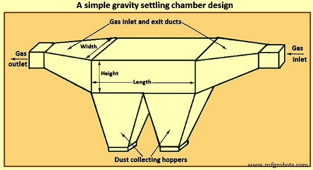
Fig 1 Een eenvoudig ontwerp van een zwaartekrachtbezinkkamer
Bij het analyseren van de prestatie van een bezinkkamer is het belangrijkste kenmerk de aard van de gasstroom door het apparaat. In dit opzicht kunnen drie geïdealiseerde basisstromingssituaties worden onderscheiden, namelijk (i) laminaire stroming, (ii) propstroming (snelheid uniform over de dwarsdoorsnede) zonder verticale menging van deeltjes, en (iii) propstroming met volledige verticale menging van deeltjes.
Laminaire stroming wordt gekenmerkt door een snelheidsprofiel van het parabolische type. Een dergelijke stroming wordt alleen gerealiseerd voor Reynoldsgetallen onder die voor overgang naar turbulente stroming. In een laminaire stroming is de tijd die een deeltje op hoogte 'h' boven de vloer van de kamer nodig heeft om te bezinken 'h/V', waarbij V de bezinkingssnelheid van het deeltje is. Verticale menging van deeltjes is afwezig in laminaire stroming. Het effect van Brownse beweging wordt normaal gesproken verwaarloosd ten opzichte van de gestage neerwaartse beweging als gevolg van bezinking.
In de bezinkkamer van de laminaire stroming is het gassnelheidsprofiel parabolisch, en als een deeltje onder de centrale stroomlijn bezinkt, ontmoet het vloeistof die langzamer beweegt, en dus neemt de verblijftijd in de kamer toe ten opzichte van wat het was op de hogere stroomlijn. Aan de andere kant ontmoeten deeltjes die zich aanvankelijk boven de centrale stroomlijn bevinden, sneller bewegende stroomlijnen als ze vallen totdat ze de centrale stroomlijn passeren.
De tweede stroomcategorie is de propstroom zonder verticale menging van de deeltjes. Dit type stroming is in zekere zin een benadering van laminaire stroming in die zin dat verticale vermenging van deeltjes nog steeds wordt genegeerd, maar er wordt uitgegaan van een vlak snelheidsprofiel en de deeltjes bezinken allemaal met hun bezinkingssnelheden. Het tweede type stromingssituatie is die van propstroming zonder verticale vermenging van deeltjes. In deze situatie wordt aangenomen dat de deeltjes gelijkmatig over de ingang van de kamer zijn verdeeld. Of een deeltje wordt opgevangen, wordt uitsluitend bepaald door de hoogte 'h' bij de ingang boven het verzameloppervlak. Een kritische hoogte 'h*' kan zodanig worden gedefinieerd dat alle deeltjes die binnenkomen met een 'h' kleiner dan of gelijk aan 'h*' worden opgevangen en die waarvoor 'h' groter is dan 'h*' ontsnappingsverzameling.
De derde categorie, propstroming met grondige verticale menging, is de turbulente stroming. In een bezinkkamer voor turbulente stroming wordt aangenomen dat de gassnelheid uniform is over de kamer vanwege de turbulente menging. Bovendien overstemt de turbulente vermenging in de kern van de kamer de neiging van de deeltjes om te bezinken en handhaaft een uniforme deeltjesconcentratie verticaal over de kamer. Verwijdering door bezinking kan worden aangenomen in een dunne laag op de bodem van de kamer.
De stroming in een rechthoekig kanaal kan als turbulent worden beschouwd als het Reynoldsgetal groter is dan 4.000. In de bezinkkamer met laminaire stroming bezinken deeltjes op alle hoogten boven de vloer van de kamer, waarbij de sleutel tot de analyse het berekenen van de totale verblijftijd van de deeltjes is wanneer ze over stroomlijnen vallen. Het mechanisme van verzameling in een bezinkkamer met turbulente stroming is, hoewel uiteindelijk gebaseerd op de bezinking van deeltjes onder zwaartekracht, nogal verschillend van dat in de laminaire stromingskamer. Het verschil is te wijten aan de turbulente stroming in de kamer. In de bulkstroom in de kamer is turbulente menging krachtig genoeg zodat deeltjes door de stroom worden overweldigd en niet neerslaan. Aangenomen wordt dat de turbulente menging een uniforme deeltjesconcentratie handhaaft over de hoogte van de kamer. Zeer dicht bij de vloer van de kamer kan worden aangenomen dat er een dunne laag bestaat waarover deeltjes zich op korte afstand tot de vloer nestelen. Dus zodra een deeltje, krachtig gemengd in de kern van de stroom, deze laag binnenkomt, bezinkt het op de vloer.
Cyclonscheidingstekens
Cycloonafscheiders zijn gasreinigingsapparaten die gebruikmaken van de centrifugale kracht die wordt gecreëerd door een draaiende gasstroom om deeltjes van een gas te scheiden. Een standaard tangentiële verticale cycloonafscheider met tegenstroom inlaat wordt getoond in figuur 2. De gasstroom wordt gedwongen om de gebogen geometrie van de cycloon te volgen, terwijl de traagheid van deeltjes in de stroom ervoor zorgt dat ze naar de buitenmuur bewegen, waar ze botsen en worden verzameld. Een deeltje met massa 'm' dat beweegt in een cirkelvormig pad met straal 'r' met een tangentiële snelheid 'vA' wordt ingewerkt door een middelpuntvliedende kracht van 'm(vA)2/r'. Bij een typische waarde van 'vA' =10 m/s, 'r' =0,5 m, is deze kracht 20,4 keer die van de zwaartekracht op hetzelfde deeltje. Het kan dus worden gezien dat de aanzienlijk grotere kracht op het deeltje dan die van alleen bezinking kan worden bereikt voor cycloongeometrie.
In een cycloon komen de deeltjes in de draaiende gasstroom steeds dichter bij de buitenwand als ze door het apparaat stromen. Zoals getoond in figuur 2, kan de gasstroom verschillende volledige bochten maken terwijl deze van het ene uiteinde van het apparaat naar het andere stroomt. Voor het ontwerp van een cycloonafscheider, de gegeven gasstroomsnelheid en binnen- en buitenradii, moet de lengte van het lichaam van de cycloon ervoor zorgen dat een gewenst verzamelrendement voor deeltjes van een bepaalde grootte wordt bereikt. Aangezien de lengte van het lichaam van een cycloon via de gasstroomsnelheid gerelateerd is aan het aantal windingen dat door de gasstroom wordt uitgevoerd, bestaat het ontwerp vaak uit het berekenen van het aantal windingen dat nodig is om een gespecificeerde opvangefficiëntie te bereiken.
Er zijn verschillende ontwerpen beschikbaar voor de cycloonafscheiders die verschillen in de manier waarop de roterende beweging aan de gasstroom wordt gegeven. Conventionele cyclonen kunnen van drie categorieën zijn, namelijk (i) tegenstroomcyclonen (tangentiële inlaat en axiale inlaat), (ii) doorstroomcyclonen en (iii) waaiercollectoren.
Fig. 2 toont een conventionele tegenstroomcycloon met een tangentiële inlaat. Het vuile gas komt bovenaan de cycloon binnen en krijgt een draaiende beweging vanwege de tangentiële invoer. Deeltjes worden door de middelpuntvliedende kracht tegen de muur gedrukt en vallen dan door de zwaartekracht naar beneden. Aan de onderkant van de cycloon keert de gasstroom om en vormt een binnenkern die aan de bovenkant van de cycloon vertrekt. In een cycloon met axiale inlaat met omgekeerde stroom wordt het inlaatgas langs de as van de cycloon ingebracht, waarbij de centrifugale beweging wordt uitgeoefend door permanente schoepen aan de bovenkant.
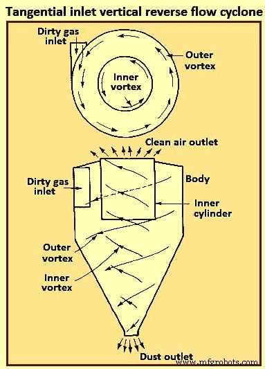
Fig 2 Tangentiële inlaat verticale tegenstroom cycloon
In straight-through-flow cyclonen verlaat de binnenste vortex van lucht aan de onderkant (in plaats van de richting om te keren), waarbij de aanvankelijke centrifugale beweging wordt gegeven door de schoepen aan de bovenkant. Dit type wordt veel gebruikt als voorreiniger om grote deeltjes te verwijderen. De belangrijkste voordelen van deze cycloon zijn lage drukval en hoge volumetrische stroomsnelheden.
In de waaiercollector komen gassen loodrecht op een waaier met veel bladen binnen en worden door de waaier rond zijn omtrek naar buiten geveegd, terwijl de deeltjes in een ringvormige gleuf rond de omtrek van de cycloon worden gegooid. Het belangrijkste voordeel van deze cycloon is zijn compactheid. Het belangrijkste nadeel van de cycloon is de neiging tot verstopping door vaste ophoping in de cycloon.
Cyclonen kunnen worden gemaakt van elk materiaal, metaal of keramiek. Ze zijn bestand tegen hoge temperaturen, schurende deeltjes of corrosieve atmosferen. Het binnenoppervlak moet glad zijn, zodat de verzamelde deeltjes gemakkelijk langs de wand naar de trechter kunnen glijden. Er zijn geen bewegende delen in een cycloon, dus de bediening is normaal gesproken eenvoudig en relatief onderhoudsvrij. Hun lage kapitaalkosten en onderhoudsvrije werking maken ze ideaal voor gebruik als voorreinigers voor efficiëntere eindcontroleapparatuur, zoals ESP's. Hoewel cyclonen van oudsher worden beschouwd als collectoren met een relatief laag rendement, kunnen sommige momenteel beschikbare cyclonen efficiënties bereiken die hoger zijn dan 98% voor deeltjes groter dan 5 micrometer. Normaal gesproken halen cyclonen routinematig een efficiëntie van 90% voor deeltjes groter dan 15 micrometer tot 20 micrometer.
Fig. 3 toont een deeltje dat tangentieel binnenkomt in een horizontaal vlak van een draaiende gasstroom bij r3 wordt beschouwd. Vanwege een middelpuntvliedende kracht van 'm(vA)2/r' volgt het deeltje een pad naar buiten over de stroomlijnen. De snelheidsvector heeft een tangentiële component (vA) en een radiale component (Vr). Er is ook een axiale component (vZ).
De zogenaamde laminaire stroming cycloonscheider heeft geen laminaire stroming in de zin van de laminaire stromingsbezinkkamer, maar eerder een wrijvingsloze stroming waarbij de stroomlijnen de contouren van de cycloon volgen zoals weergegeven in figuur 3.
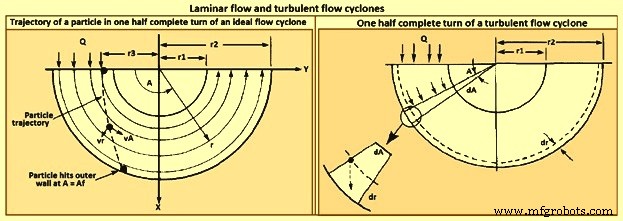
Fig 3 laminaire stroming en turbulente stromingscyclonen
Het model van de turbulente cycloonafscheider wordt getoond in figuur 3. Vanwege turbulente menging wordt aangenomen dat de deeltjesconcentratie uniform is over de cycloon, en, zoals in het geval van de turbulente stromingsbezinkkamer, vindt verwijdering plaats over een dunne laag bij de buitenmuur.
De efficiëntie van de cycloonopvang neemt toe met toenemende (i) deeltjesgrootte, (ii) deeltjesdichtheid, (iii) inlaatgassnelheid, (iv) lichaamslengte van de cycloon, (v) aantal gasomwentelingen en (vi) gladheid van de cycloonwand. Aan de andere kant neemt de efficiëntie van de cycloon af met toenemende (i) cycloondiameter, (ii) gasuitlaatkanaaldiameter en (iii) gasinlaatoppervlak. Voor elke specifieke cycloon, waarvan de verhouding van afmetingen vast is, neemt het verzamelrendement toe naarmate de cycloondiameter kleiner wordt. Het ontwerp van een cycloonafscheider vertegenwoordigt een compromis tussen opvangefficiëntie, drukval en grootte. Higher efficiencies need higher pressure drops (i.e., inlet gas velocities) and larger sizes (i.e. body length). The dimensions required to specify a tangential-entry, reverse-flow cyclone are shown in Fig 4.
Besides collection efficiency the other major consideration in cyclone specification is pressure drop. While higher efficiencies are achieved by forcing the gas through the cyclone at higher velocities, to do so results in an increased pressure drop. Since increased pressure drop needs increased energy input into the gas, there is ultimately an economic trade-off between collection efficiency and operating cost. Cyclone pressure drops normally range from 250 Pa to 4,000 Pa.
Electrostatic precipitator
ESP is one of the most widely used particulate control device. It has wide size ranges. The ESP chamber consists of two electrodes, the discharge and the collecting electrodes. Between the electrodes, the gas contains free electrons, ions, and charged particles. The species contributing to the space charge density are ions, electrons, and charged particles. The gas molecules capture all the free electrons so that only the ions and charged particles contribute space charge density. Actually, ionic current flows in the direction of the electric field consisting of ions charged with the same polarity as the charging electrode and moving to the collecting electrode. The ions migrate to the collecting electrode with a velocity large enough to be unaffected by the turbulent flow in the chamber.
The basic principle of operation of the ESP is that the particles are charged, and then an electric field is imposed on the region through which the particle-laden gas is flowing, exerting an attractive force on the particles and causing them to migrate to the oppositely charged electrode at right angles to the direction of gas flow. ESP differs from mechanical methods of particle separation in that the external force is applied directly to the individual particles rather than indirectly through forces applied to the entire gas stream (e.g. in a cyclone separator). Particles collect on the electrode. If the particles collected are liquid, then the liquid flows down the electrode by gravity and it is removed at the bottom of the device. If the particles are solid, the collected layer on the electrode is removed periodically by rapping the electrode.
Particle charging is achieved by generating ions by means of a corona established surrounding a highly charged electrode like a wire. The electric field is applied between that electrode and the collecting electrode. If the same pair of electrodes serves for particle charging and collecting, the device is called a single-stage ESP (Fig 4). A wire serving as the discharge electrode is suspended down the axis of a tube and held in place by a weight attached at the bottom. The sides of the cylinder form the collecting electrode. The collected particles which form a layer on the collecting electrode are removed to the dust hopper by rapping the collecting electrode. In a two-stage ESP, separate electrode pairs perform the charging and collecting functions.
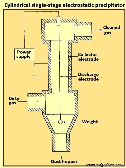
Fig 4 Cylindrical single-stage electrostatic precipitator
Most industrially generated particles are charged during their formation by such means as flame ionization and friction, but normally only to a low or moderate degree. These natural charges are far too low for electrostatic precipitation. The high-voltage DC (direct current) corona is the most effective means for particle charging and is universally used for electrostatic precipitation. The corona is formed between an active high voltage electrode such as a fine wire and a passive ground electrode such as a plate or pipe. The corona surrounding the discharge electrode can lead to the formation of either positive or negative ions which migrate to the collecting electrode. The ions, in migrating from the discharging to the collecting electrode, collide with the particulate matter and charge the particles.
Since the gas molecule ions are many orders of magnitude smaller than even the smallest particles and because of their great number, virtually all particles that flow through the device become charged. The charged particles are then transported to the collecting electrode, to which they are held by the electrostatic attraction. The particles build a thickening layer on the collecting electrode. The charge slowly bleeds from the particles to the electrode. As the layer grows, the charges on the most recently collected particles are to be conducted through the layer of previously collected particles. The resistance of the dust layer is called the dust resistivity.
As the particle layer grows in thickness, the particles closest to the plates lose most of their charge to the electrode. As a result, the electrical attraction between the electrode and these particles is weakened. However, the newly arrived particles on the outside layer have a full charge. Because of the insulating layer of particles, these new particles do not lose their charge immediately and thus serve to hold the entire layer against the electrode. Finally, the layer is removed by rapping, so that the layer breaks up and falls into a collecting hopper. ESPs are normally employed for gas cleaning when the volumetric throughput of gas is high.
The mechanism for particle charging in a ESP is the generation of a supply of ions which attach themselves to the particles. The corona is the mechanism for forming ions. The corona can be either positive or negative. A gas normally has a few free electrons and an equal number of positive ions, a situation which is exploited in generating a corona. When a gas is placed between two electrodes, small amount of current results as the free electrons migrate to the positive electrode and the positive ions migrate to the negative electrode.
In the positive corona discharge electrode, the wire in the cylindrical ESP (Fig 4) is at a positive potential. The few free electrons normally present in the gas migrate toward the wire. As the electrons approach the wire, the electrons’ energy is increased because of an increase in the attractive force. These free electrons collide with gas molecules, the collision leading in some cases to the ejection of an electron from the molecule, producing two free electrons and a positive ion. The two free electrons continue toward the positive electrode, gaining energy, until they collide with two more gas molecules, producing four free electrons and two positive ions. This process is referred to as an electron avalanche.
The positive ions formed migrate to the negative electrode. It is these positive ions which migrate across the entire device to the negative electrode that collide with and attach to the particles in the gas. The region immediately surrounding the wire in which the electron avalanche is established is the corona. Thus, with a positive corona the particles become positively charged. The term ‘corona’ arises from the fact that the electron avalanche is frequently accompanied by the production of light. In the negative corona the discharge electrode is maintained at a negative potential.
The electron avalanche begins at the outer surface of the wire and proceeds radially outward. Close to the wire the electrons are sufficiently energetic to form positive ions upon collision with gas molecules, thus initiating the electron avalanche. The positive ions formed migrate the short distance to the wire. As the electrons migrate outward into a region of lower electric field strength, they are slowed down by collisions with gas molecules. These electrons eventually have lower energy than those which are accelerated toward the positive electrode in the positive corona. These relatively low energy electrons, rather than ejecting an electron from the gas molecule upon collision, are absorbed by the gas molecules to produce negative ions. The formation of negative ions, which begins to occur at the outer edge of the corona, essentially absorbs all the free electrons produced in the electron avalanche at the wire surface. These negative ions then migrate to the positive electrode, in the course of which attaching to gas molecules and forming negative ions.
For a negative corona to be effective, it is necessary that the gas molecules can absorb free electrons to form negative ions. Sulphur dioxide is one of the best electron absorbing gases of those present in flue gases. Oxygen, CO2, and H2O are also effective electron absorbers. The negative corona is normally more stable than the positive corona, so it is preferred in most industrial applications. A by-product of the negative corona is the production of ozone (O3). The positive corona does not need an electron-absorbing gas.
As the ESP is operated, a layer of the collected material builds up on the collecting electrode. Particle deposits on the precipitator collection surface are to possess at least a small degree of electrical conductivity in order to conduct the ion currents from the corona to ground. The minimum conductivity required is around 10 to the power -10 per ohm-centimeter (resistivity of 10 to the power 10 ohm-centimeter). This conductivity is small compared to that of ordinary metals but is much greater than that of good insulators such as silica and most plastics. The resistivity of a material is determined by establishing a current flow through a slab of known thickness of the material.
As long as the resistivity of the collected dust layer is less than about 10 to the power 10 ohm-centimeter, the layer surrender its charge to the electrode. At the room temperature, a typical dust has a resistivity of around 10 to the power 8 ohm-centimeter. This is because of a layer of water on the surface of the particles. As the temperature is increased beyond 100 deg C, the water is evaporated and the resistivity increases to a value characteristic of the collected solids. When the resistivity of the layer exceeds around 10 to the power 10 ohm-centimeter, the potential across the layer increases so that the voltage which can be maintained across the ESP decreases and the collection efficiency decreases. The electrical resistivity of collected particulate matter depends on its chemical composition, the constituents of the gas, and the temperature.
Particle charging in ESP occurs in the gas space between the electrodes where the gas ions generated by the corona bombard and become attached to the particles. The gas ions can reach concentrations as high as 10 to the power 15 ions per cubic meter. The level of charge attained by a particle depends on the gas ion concentration, the electric field strength, the conductive properties of the particle, and the particle size. A 1 micrometer particle typically acquires the order of 300 electron charges, whereas a 10 micrometer particle can attain 30,000 electron charges. Predicting the level of charge acquired by a particle is necessary in order to predict the particle’s migration velocity, on the basis of which the collection efficiency can be calculated for a given set of operating conditions.
There are actually two mechanisms by which particles become charged in an ESP. In the first mechanism particle charging occurs when ions which are migrating toward the collecting electrode encounter particles to which they become attached. In migrating between the electrodes the ions follow the electric flux lines, which are curves everywhere tangent to the electric field vector. When the particle first enters the device and is uncharged, the electric flux lines deflect toward the particle, resulting in the capture of even a larger number of ions than are captured if the ions have followed their normal path between the electrodes. As the particle becomes charged, ions begin to be repelled by the particle, reducing the rate of charging. Eventually, the particle acquires a saturation charge and charging ceases. This mechanism is called ion bombardment or field charging.
The second mode of particle charging is diffusion charging, in which the particle acquires a charge by virtue of the random thermal motion of ions and their collision with and adherence to the particles. Diffusion charging occurs as the ions in their random thermal motion collide with a particle and surrender their charge to it. In that sense the mechanism of diffusion charging is identical to that of the diffusion of uncharged vapour molecules to the surface of a particle. However, because both the particle and the ions are charged, the random thermal motion of the ions in the vicinity of a particle is influenced by an electrostatic force. This force gives rise to a tendency of the ions to migrate away from the particle as the particle charge increases. The overall flux of ions to a particle hence is both the random diffusive motion and the electrical migration.
The theories of both field and diffusion charging, in their full generality, are quite complex and have received a great deal of attention. Strictly speaking, field and diffusion charging occur simultaneously once a particle enters an ESP, and hence to predict the overall charge acquired by a particle, one is to consider the two mechanisms together. However, since the diffusion charging is predominant for particles smaller than around 1 micrometer in diameter and field charging is predominant for particles larger than around 1 micrometer, the two mechanisms frequently are treated in ESP design as if they occur independently. In doing so, one estimates the total charge on a particle as the sum of the charges resulting from each of the two separate mechanisms.
Filtration of particles from gas streams
A major class of particulate air pollution control devices relies on the filtration of particles from gas streams. A variety of filter media is employed, including fibrous beds, packed beds, and fabrics. Fibrous beds used to collect airborne particles are typically quite sparsely packed, usually only around 10 % of the bed volume being fibers. Packed bed filters consist of solid packing normally in a tube and tend to have higher packing densities than do fibrous filters. Both fibrous and packed beds are widely used in the ventilation systems. Fabric filters are frequently used to remove solid particles from industrial gases, whereby the dusty gas flows through fabric bags and the particles accumulate on the cloth.
The physical mechanisms by which the filtration is accomplished vary depending on the mode of filtration. Conventional sparsely packed fibrous beds can be viewed as assemblages of cylinders. In such a filter, the characteristic spacing between fibers is much larger than the size of the particles being collected. Thus the mechanism of collection is not simply sieving, in which the particles are trapped in the void spaces between fibers. Rather, the removal of particles occurs by the transport of particles from the gas to the surface of a single collecting element. Because the filtration mechanisms in a fibrous bed can be analyzed in terms of a single collector, it is possible to describe them in considerable theoretical detail.
Packed-bed filters are sometimes viewed as assemblages of interacting, but essentially separate, spherical collectors, although the close proximity of individual packing elements casts doubt as to the validity of this approach. Because of the relatively closer packing in packed-bed filters, and the resulting difficulty of describing the particle collection process in clean theoretical terms, predicting collection in such systems is more empirically based than for fibrous filters. Fabric filter efficiencies must be predicted strictly empirically since the accumulated particle layer actually does the collecting.
A fibrous filter bed is viewed as a loosely packed assemblage of single cylinders. Even though the fibers are oriented in all directions in the bed, from a theoretical point of view the bed is treated as if every fiber is normal to the gas flow through the bed. The solid fraction of the filter is normally of the order of only 10 %. In addition, each fiber acts more or less independently as a collector. Thus, to compute the particle removal by a filter bed, one basically needs to determine the number of fibers per unit volume of the bed and then multiply that quantity by the efficiency of a single fiber.
The basis of predicting the collection efficiency of a filter bed is the collection efficiency of a single filter element in the bed. The filter element is taken as an isolated cylinder normal to the gas flow. Three distinct mechanisms as given below can be identified whereby particles in the gas reach the surface of the cylinder.
As per the first mechanism, the particles in a gas undergo Brownian diffusion which brings some particles in contact with the cylinder due to their random motion as they are carried past the cylinder by the flow. A concentration gradient is established after the collection of a few particles and acts as a driving force to increase the rate of deposition over that which occurs in the absence of Brownian motion. Because the Brownian diffusivity of particles increases as particle size decreases, it is normally expected that this removal mechanism is the most important for very small particles. When analyzing collection by Brownian diffusion, the particles are treated as diffusing mass-less points.
As per the second mechanism, interception takes place when a particle, following the streamlines of flow around a cylinder, is of a size sufficiently large that its surface and that of the cylinder come into contact. Thus, if the streamline on which the particle centre lies is within a distance Dp /2 of the cylinder, interception occurs. Here Dp is the particle diameter.
As per the third mechanism, inertial impaction occurs when a particle is unable to follow the rapidly curving streamlines around an obstacle and, because of its inertia, continues to move toward the obstacle along a path of less curvature than the flow streamlines. Thus, collision occurs because of the particle’s momentum. It is to be noted that the mechanism of inertial impaction is based on the premise that the particle has mass but no size, whereas interception is based on the premise that the particle has size but no mass.
Collection can also result from electrostatic attraction when either particles or fiber or both possess a static charge. These electrostatic forces can be either direct, when both particle and fiber are charged, or induced, when only one of them is charged. Such charges are normally not present unless deliberately introduced during the production of the fiber.
The size ranges in which the various mechanisms of collection are important are (i) Inertial impaction – greater than 1 micrometer, (ii) Interception – greater than 1 micrometer, (iii) diffusion – less than 0.5 micrometer, and (iv) electrostatic attraction – 0.01 micrometer to 5 micrometer. It is normal to analyze the mechanisms of collection separately and then combine the individual efficiencies to give the overall collection efficiency for the cylinder or other obstacle.
Most developments of particle collection assume, for lack of better information, that particles transported to the surface of a fiber are retained by the fiber. Experiments have shown, however, that for a variety of substances and filter media, the fraction of particles striking the collector surface which adhere is generally less than unity and can in some cases be as low as 0.5.
Industrial fabric filtration is normally accomplished in a so-called bag- house, in which the particle-laden gases are forced through filter bags. Particles are normally removed from the bags by gravity. Fig 5 shows three bag-house designs, in which cleaning is accomplished by vibration (Fig 5a), air jet [Fig 5b), or traveling ring [Fig 5c).
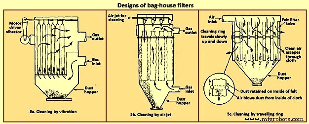
Fig 5 Designs of bag house filters
The fabric filtration process consists of three phases. First, particles collect on individual fibers by the above described mechanisms. Then an intermediate stage exists during which particles accumulate on previously collected particles, bridging the fibers. Finally, the collected particles form a cake in the form of a dust layer which acts as a packed bed filter for the incoming particles. As the dust layer accumulates, the pressure drop across the filter increases, and periodically the dust layer is to be dislodged into the hopper at the bottom to ‘regenerate’ the fabric bag. High efficiencies are attainable with fabric filters, particularly in treating combustion gases from the technological processes. To the extent that effective operation of an ESP depends on the presence of SO2 in the gas as an ionizable species, fabric filters can operate with no loss of efficiency with low-sulphur level.
Fabric filters consist of semi-permeable woven or felted materials which constitute a support for the particles to be removed. A brand-new woven filter cloth has fibers roughly 100 micrometers to 150 micrometers in diameter with open spaces between the fibers of 50 micrometers to 75 micrometers. Initially, the collection efficiency of such a cloth is low because most of the particles pass directly through the fabric. However, deposited particles quickly accumulate, and it is the deposited particle layer that enables the high-efficiency removal once a uniform surface layer has been established.
Although fiber mat filters are similar in some respects to fabric filters, they do not depend on the layer of accumulated particles for high efficiency. Fiber mat filters generally are not cleaned but are discarded. They are ordinarily used when particle concentrations are low, so that reasonable service life can be achieved before discarding.
In a fabric filter the particle layer performs the removal task. As the layer of collected particles grows in thickness, there is an increase in the pressure drop across the particle layer and the underlying fabric. The two major considerations in the design of a fabric filter assembly are the collection efficiency and the pressure drop as a function of time of operation (since the last cleaning). The collection efficiency depends on the local gas velocity and the particle loading on the fabric.
Fabric filters offer the several advantages such as (i) they can achieve very high collection efficiencies even for very small particles, (ii) they can be used for a wide variety of particles, (iii) they can operate over a wide range of volumetric flow rates, and (iv) they need only moderate pressure drops. The limitations of fabric filters are namely (i) operation is to be carried out at temperatures lower than that at which the fabric is destroyed, or its life is shortened to an uneconomical degree, (ii) gas or particle constituents which attack the fabric or prevent proper cleaning, such as sticky particles difficult to dislodge, are to be avoided, and (iii) bag houses need large floor areas. The advantages of fabric filter bag houses clearly outweigh their limitations.
Wet collectors
Wet collectors, or scrubbers, employ water washing to remove particles directly from a gas stream. Scrubbers can be grouped broadly into two main classes namely (i) those in which an array of liquid drops (sprays) form the collecting medium, and (ii) those in which wetted surfaces of various types constitute the collecting medium. The first class includes spray towers and venturi scrubbers, while the second includes plate and packed towers.
Scrubbing is a very effective means of removing small particles from a gas. Removal of particles results from collisions between particles and water drops. In the humid environment of a scrubber, small, dry particles also grow in size by condensation of water and thereby become easier to remove. Re-entrainment of particles is avoided since the particles become trapped in droplets or in a liquid layer. A scrubber also provides the possibility of simultaneously removing soluble gaseous pollutants. The particle-laden scrubbing liquid is to be disposed of, a problem not encountered in dry methods of gas cleaning.
A spray scrubber is a device in which a liquid stream is broken into drops, approximately in the range 0.1 mm to 1 mm in diameter, and introduced into the particle laden gas stream. The array of moving drops becomes a set of targets for collection of the particles in the gas stream. Collection efficiency is computed by considering the efficiency of a single spherical collector and then summing over the number of drops per unit volume of gas flow. The relative motion between the drops and particles is an important factor in the collection efficiency since capture occurs by impaction and direct interception. Diffusion is also important for smaller particles.
There are two general types of spray scrubbers. The first class comprises those having a preformed spray where drops are formed by atomizer nozzles and sprayed into the gas stream. These include (i) counter-current gravity tower, where drops settle vertically against the rising gas stream, (ii) cross-current tower, where drops settle through a horizontal gas stream, and (iii) co-current tower, where spray is horizontal into a horizontal gas stream.
The second class comprises those in which the liquid is atomized by the gas stream itself. Liquid is introduced more or less in bulk into a high-velocity gas flow which shatters the liquid into drops. Devices in this class are called venturi scrubbers since the high velocity gas flow is achieved in a venturi (a contraction). Fig 6 shows four types of wet collection equipment.
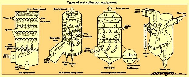
Fig 6 Types of wet collection equipment
The simplest type of wet collector is a spray tower into which water is introduced by means of spray nozzles (Fig 6a). Gas flow in a spray chamber is counter-current to the liquid, the configuration leading to maximum efficiency. Collection efficiency can be improved over the simple spray chamber with the use of a cyclonic spray tower, as shown in Fig 6b. The liquid spray is directed outward from nozzles in a central pipe. An unsprayed section above the nozzles is provided so that the liquid drops with the collected particles have time to reach the walls of the chamber before exit of the gas. An impingement plate scrubber, as shown in Fig 6c, consists of a tower containing layers of baffled plates with holes (5,000 to 50,000 per square meter) through which the gas must rise and over which the water must fall. Highest collection efficiencies of wet collectors are obtained in a venturi scrubber, shown in Fig 6d, in which water is introduced at right angles to a high-velocity gas flow in a venturi tube, resulting in the formation of very small water droplets by the flow and high relative velocities of water and particles. The high gas velocity is responsible for the breakup of the liquid. Aside from the small droplet size and high impingement velocities, collection is enhanced through particle growth by condensation. Different types of particle scrubbing devices are described below.
Plate scrubber – It is a vertical tower containing one or more horizontal plates (trays). Gas enters the bottom of the tower and must pass through perforations in each plate as the gas flows counter-current to the descending water stream. Plate scrubbers are normally named for the type of plates they contain (e.g. sieve plate tower). Collection efficiency increases as the diameter of the perforations decreases. A cut diameter, that collects with 50 % efficiency, of around 1 micrometer aerodynamic diameter can be achieved with 3.2 mm diameter holes in a sieve plate.
Packed-bed scrubber – It operates similarly to packed-bed gas absorber. Collection efficiency increases as packing size decreases. A cut diameter of 1.5 micrometers aerodynamic diameter can be attained in columns packed with 2.5 cm elements.
Spray scrubber – In this scrubber, particles are collected by liquid drops which have been atomized by spray nozzles. Horizontal and vertical gas flows are used, as well as spray introduced co-current, counter-current, or cross-flow to the gas. Collection efficiency depends on droplet size, gas velocity, liquid / gas ratio, and droplet trajectories. For droplets falling at their terminal velocity, the optimum droplet diameter for fine-particle collection lays in the range 100 micrometers to 500 micrometers. Gravitational settling scrubbers can achieve cut diameters of around 2 micrometers. The liquid / gas ratio is in the range 0.001 cum to 0.01 cum per cum of gas treated.
Venturi scrubber – A moving gas stream is used to atomize liquids into droplets. High gas velocities (60 m/sec to 120 m/s) lead to high relative velocities between gas and particles and promote collection.
Cyclone scrubber – Drops can be introduced into the gas stream of a cyclone to collect particles. The spray can be directed outward from a central manifold or inward from the collector wall.
Baffle scrubber – In this scrubber, there are changes in gas flow velocity and direction induced by solid surfaces.
Impingement-entrainment scrubber – The gas is forced to impinge on a liquid surface to reach a gas exit. Some of the liquid atomizes into drops which are entrained by the gas. The gas exit is designed so as to minimize the loss of entrained droplets.
Fluidized-bed scrubber – A zone of fluidized packing is provided where gas and liquid can mix intimately. Gas passes upward through the packing, while liquid is sprayed up from the bottom and / or flows down over the top of the fluidized layer of packing.
The collection efficiency of wet collectors can be related to the total energy loss in the equipment. The higher is the scrubber power per unit volume of gas treated, the better is the collection efficiency. Almost all the energy is introduced in the gas, and thus the energy loss can be measured by the pressure drop of gas through the unit. The major advantage of wet collectors is the wide variety of types, allowing the selection of a unit suitable to the particular removal problem. As regards disadvantages, high pressure drops (and hence energy requirements) are to be maintained, and the handling and disposal of large volumes of scrubbing liquid are to be undertaken.
In case of spray scrubbing, the conceptually simplest of the devices is a gravity spray chamber. Water droplets are introduced at the top of an empty chamber through atomizing nozzles and fall freely at their terminal settling velocities counter-currently through the rising gas stream. The particle-containing liquid collects in a pool at the bottom and is to be pumped out for treatment to remove the solids, and the cleaned liquid is normally recycled to the tower. The overall efficiency of a spray tower increases as the collection efficiency of a single drop increases, as the length of the chamber increases, and as the ratio of the volumetric flow rate of water to that of gas increases. It increases as the diameter of the drops decreases.
Venturi scrubbers are used when high collection efficiencies are needed and when most of the particles are smaller than 2 micrometers in diameter. There are a number of examples, in fact, where a venturi scrubber is the only practical device for a gas-cleaning application. If the particles to be removed are sticky, flammable, or highly corrosive, for example, ESPs and fabric filters cannot be used. Venturi scrubbers are also the only high-efficiency particulate collectors which can simultaneously remove gaseous species from the effluent stream.
The distinguishing feature of a venturi scrubber is a constricted cross section or throat through which the gas is forced to flow at high velocity. A typical venturi scrubber configuration is shown in Fig 7. The configuration includes a converging conical section where the gas is accelerated to throat velocity, a cylindrical throat, and a conical expander where the gas is slowed down. Liquid can be introduced either through tangential holes in the inlet cone or in the throat itself. In the former case, the liquid enters the venturi as a film on the wall and flows down the wall to the throat, where it is atomized by the high-velocity gas stream. In the latter, the liquid is injected perpendicular to the gas flow in the throat, atomized, and then accelerated. Gas velocities in the range 60 m/sec to 120 m/sec are achieved, and the high relative velocity between the particle laden gas flow and the droplets promotes collection. The collection process is essentially complete by the end of the throat. Because they operate at much higher velocities than ESPs precipitators or bag houses, venturi scrubbers are physically smaller and can be economically made of corrosion-resistant materials. Venturis have the simplest configuration of the scrubbers and are the smallest in size. Fig 7 shows the comparison of the efficiency of venturi scrubber with the efficiencies of other gas cleaning devices.
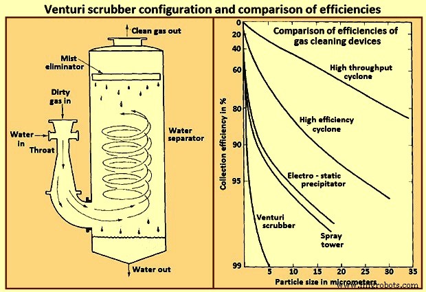
Fig 7 Venturi scrubber configuration and comparison of efficiencies
A typical range of liquid to gas flow rate ratios for a venturi scrubber is 0.001 cum to 0.003 cum of liquid per cum of gas. At the higher liquid / gas ratios, the gas velocity at a given pressure drop is reduced, and at lower ratios, the velocity is increased. For gas flow rates exceeding about 1,000 cum / minute venturi scrubbers are normally constructed in a rectangular configuration in order to maintain an equal distribution of liquid over the throat area.
Productieproces
- Een blik op leveranciers van RTLS Healthcare (en de technologieën die zij aanbieden)
- Toegangscontrole met QR, RFID en temperatuurverificatie
- Raspberry Pi-sensor en actuatorbediening
- Volledige controle en beheer van automatiseringssystemen wereldwijd
- Mogelijkheden en voordelen van robotinspectietechnologieën en -systemen
- Netheid IS iFP Onderdelenreinigings- en wassystemen
- Lasgassen:101 Waarom we het gebruiken en hun soorten
- Toepassingen en voordelen van het gebruik van een gasbewakingsoplossing
- 5 industrieën waar gasdetectiesystemen zeer essentieel zijn
- SCADA-systemen en industrie 4.0
- Onderdelen en elementen van CNC-machinesystemen