Resistive Random Access Memory (RRAM):een overzicht van materialen, schakelmechanisme, prestaties, opslag op meerdere niveaus (mlc), modellering en toepassingen
Abstract
In dit manuscript wordt de recente vooruitgang op het gebied van resistive random access memory (RRAM)-technologie, die wordt beschouwd als een van de meest opvallende opkomende geheugentechnologieën vanwege zijn hoge snelheid, lage kosten, verbeterde opslagdichtheid, mogelijke toepassingen op verschillende gebieden en uitstekende schaalbaarheid wordt uitgebreid beoordeeld. Eerst wordt een kort overzicht gegeven van het gebied van opkomende geheugentechnologieën. De materiaaleigenschappen, het weerstandsschakelmechanisme en de elektrische eigenschappen van RRAM worden besproken. Ook worden verschillende zaken zoals uithoudingsvermogen, retentie, uniformiteit en het effect van bedrijfstemperatuur en willekeurige telegraafruis (RTN) uitgewerkt. Een discussie over multilevel cell (MLC) opslagcapaciteit van RRAM, die aantrekkelijk is voor het bereiken van een verhoogde opslagdichtheid en lage kosten, wordt gepresenteerd. Er zijn verschillende bedieningsschema's verschaft om een betrouwbare MLC-werking te bereiken, samen met hun fysieke mechanismen. Bovendien wordt in dit werk een uitgebreide beschrijving van schakelmethodologieën en stroomspanningsrelaties voor verschillende populaire RRAM-modellen behandeld. De toekomstige toepassingen van RRAM op verschillende gebieden, zoals beveiliging, neuromorfe computers en niet-vluchtige logische systemen, worden kort besproken. Dit overzichtsartikel wordt afgesloten met de discussie over de uitdagingen en toekomstperspectieven van het RRAM.
Inleiding
Random Access Memory, ook wel RAM genoemd, kan vluchtig of niet-vluchtig zijn. Een vluchtig geheugen verliest zijn eerder opgeslagen gegevens bij het verwijderen van de voeding, zoals het geval is voor dynamisch willekeurig toegankelijk geheugen (DRAM) en statisch willekeurig toegankelijk geheugen (SRAM). Voor niet-vluchtig geheugen blijft de inhoud die eerder is opgeslagen behouden, zelfs nadat de voeding is verwijderd. Flash-geheugen is een typisch voorbeeld van niet-vluchtig geheugen. Geheugentechnologieën combineren de voor- en nadelen om hogere prestaties te bereiken, b.v. DRAM's die in een computersysteem worden gebruikt, hebben een hoge capaciteit en dichtheid, maar ze zijn vluchtig, wat betekent dat ze om de paar milliseconden moeten worden vernieuwd. Door deze verfrissing neemt het energieverbruik van het apparaat toe wat niet wenselijk is. SRAM, aan de andere kant, is snel, maar het is ook vluchtig, net als de DRAM; bovendien zijn SRAM-cellen groter van formaat, wat de implementatie ervan op grote schaal belemmert. Flash-geheugen, dat in wezen bestaat uit een metaaloxide-halfgeleider-veldeffecttransistor (MOSFET) naast een zwevende poort in elke geheugencel, wordt momenteel op grote schaal gebruikt, met name voor de ingebedde toepassingen vanwege de lage kosten en hoge dichtheid . Afhankelijk van hoe geheugencellen zijn georganiseerd, wordt Flash-geheugen geclassificeerd als NOR Flash en NAND Flash [1]. In NOR Flash worden cellen afzonderlijk gelezen en geprogrammeerd omdat ze parallel zijn aangesloten op bitlijnen. Dit lijkt op de parallelle aansluiting van transistors in een CMOS NOR-poortarchitectuur. In het geval van NAND Flash lijkt de architectuur op die van een CMOS NAND-poort, aangezien de cellen in serie zijn verbonden met de bitlijnen. Opgemerkt moet worden dat de serieschakeling minder ruimte in beslag neemt in vergelijking met de parallelle aansluiting, wat resulteert in lagere kosten van NAND Flash. Beide typen Flash-geheugens hebben echter verschillende nadelen, zoals een lage werksnelheid (schrijf-/wistijd:1 ms/0,1 ms), beperkte duurzaamheid (10 6 schrijf-/wiscycli) en hoge schrijfspanning (> 10 V) [2].
De hierboven genoemde geheugentechnologieën, d.w.z. DRAM, SRAM en Flash, zijn op ladingsopslag gebaseerde geheugens. DRAM slaat de informatie op in de vorm van lading op de condensator en SRAM is gebaseerd op de opslag van lading op de knooppunten van de kruisgekoppelde omvormers, terwijl de Flash-geheugentechnologie de zwevende poort van de transistor gebruikt om de lading op te slaan. Al deze bestaande op ladingopslag gebaseerde geheugentechnologieën worden momenteel geconfronteerd met uitdagingen om te schalen naar een 10 nm-knooppunt of verder. Dit wordt toegeschreven aan het verlies van opgeslagen lading op nanoschaal, wat resulteert in de verslechtering van de prestaties, betrouwbaarheid en ruismarge. Bovendien vormen de vereisten van een groot dynamisch verversingsvermogen voor DRAM en lekvermogen voor zowel SRAM als DRAM ernstige uitdagingen voor het ontwerp van de toekomstige geheugenhiërarchie.
Daarom is er momenteel een nieuwe klasse van geheugens die gewoonlijk worden aangeduid als opkomende geheugentechnologieën en wordt actief onderzocht, voornamelijk in de industrie met als doel een revolutie teweeg te brengen in de bestaande geheugenhiërarchie [3]. Deze opkomende geheugentechnologieën zijn bedoeld om de schakelsnelheid van SRAM, opslagdichtheid vergelijkbaar met die van DRAM en de niet-vluchtigheid van Flash-geheugen te integreren, en worden zo zeer aantrekkelijke alternatieven voor toekomstige geheugenhiërarchie.
Om een geheugenapparaat als ideaal te classificeren, moet het de volgende kenmerken hebben:lage bedrijfsspanning (<1 V), lange cyclusduurzaamheid (>10 17 cycli), verbeterde gegevensretentietijd (>10 jaar), laag energieverbruik (fJ/bit) en superieure schaalbaarheid (<10 nm) [4]. Tot op heden is er echter geen enkel geheugen dat aan deze ideale eigenschappen voldoet. Verschillende opkomende geheugentechnologieën worden actief onderzocht om aan een deel van deze ideale geheugenkenmerken te voldoen. Deze geheugentechnologieën die afhankelijk zijn van de verandering van weerstand in plaats van lading om de informatie op te slaan, zijn als volgt:(i) faseveranderingsgeheugen (PCM), (ii) spin-transfer koppel magnetoweerstandsgeheugen (STT-MRAM), en ( iii) resistief willekeurig toegankelijk geheugen (RRAM). In faseveranderingsgeheugen bestaat het schakelmedium uit een chalcogenidemateriaal (gewoonlijk Ge2 -Sb2 -Te5 , GST) [5–7]. PCM vertrouwt op het verschil in weerstand tussen de kristallijne fase en de amorfe fase voor efficiënte gegevensopslag. De kristallijne fase duidt de toestand met lage weerstand (LRS) of AAN van het apparaat aan, terwijl de amorfe fase de toestand met hoge weerstand (HRS) of UIT aangeeft. De SET-bewerking komt overeen met LRS die over het algemeen verwijst naar het opslaan van logische waarde '1', terwijl de RESET-bewerking overeenkomt met HRS dat logische waarde '0' in het apparaat opslaat. Voor de SET-werking wordt PCM verwarmd tot boven zijn kristallisatietemperatuur bij het aanleggen van een spanningspuls, terwijl voor de RESET-werking een grotere elektrische stroom door de cel wordt gevoerd en vervolgens abrupt wordt onderbroken om te smelten en vervolgens het materiaal af te schrikken om de amorfe staat bereiken.
In magnetoresistief random access-geheugen met spin-overdracht koppel is de opslagcapaciteit te wijten aan de magnetische tunnelovergang (MJT) [8-10], die bestaat uit twee ferromagnetische lagen en een tunneling-diëlektricum daartussen. De magnetische richting van de referentielaag is vast, terwijl de toepassing van een extern elektromagnetisch veld de magnetische richting van de vrije ferromagnetische laag kan veranderen. Als de referentielaag en de vrije laag dezelfde magnetisatierichting hebben, spreekt men van de MTJ in de LRS. Voor MTJ, om in de HRS te zijn, is de richting van de magnetisatie van twee ferromagnetische lagen anti-parallel. RRAM bestaat uit een isolerende laag (I) die is ingeklemd tussen de twee metalen (M) elektroden [11, 12]. RRAM vertrouwt op de vorming en breuk van geleidende filamenten die respectievelijk overeenkomen met LRS en HRS in de isolator tussen twee elektroden [13-15].
Een gedetailleerde vergelijking van bestaande en opkomende geheugentechnologieën wordt getoond in Tabel 1. Zoals uit de tabel blijkt, hebben STT-MRAM en PCM voordelen van een kleiner gebied in vergelijking met dat van SRAM. Terwijl STT-MRAM een hoge schrijf-/leessnelheid, een lange levensduur en een laag programmeervoltage biedt, heeft PCM aan de andere kant het nadeel van een uitgebreide schrijflatentie. RRAM heeft een lagere programmeerspanning en een hogere schrijf-/leessnelheid in vergelijking met Flash en wordt gezien als potentiële vervanging van Flash-geheugen. Van alle opkomende kandidaten voor geheugentechnologie heeft RRAM aanzienlijke voordelen, zoals eenvoudige fabricage, eenvoudige metaal-isolator-metaal (MIM) -structuur, uitstekende schaalbaarheid, nanosecondensnelheid, lange gegevensretentie en compatibiliteit met de huidige CMOS-technologie, waardoor het een concurrerende oplossing voor toekomstig digitaal geheugen [16]. De belangrijkste voordelen van RRAM zijn weergegeven in Fig. 1.
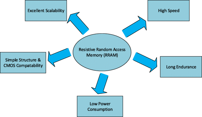
Voordelen van RRAM
In dit werk worden recente vorderingen en een gedetailleerd overzicht van de RRAM-technologie gepresenteerd. Een overzicht van schakelmaterialen samen met de classificatie van schakelmodi en details van het schakelmechanisme wordt besproken in de sectie "Resistive Random Access Memory (RRAM)". De sectie "Prestatiestatistieken van resistief Random Access Memory (RRAM)" belicht verschillende prestatiestatistieken van RRAM. Multilevel cell (MLC) kenmerken van RRAM samen met verschillende MLC-bedieningsschema's en hun fysieke mechanismen worden geanalyseerd in de sectie "Multilevel Resistive Random Access Memory (RRAM)". Een gedetailleerde bespreking van het modelleren van RRAM-apparaten wordt gepresenteerd in de sectie "Modelleren van RRAM-apparaten". In de sectie "Toepassingen van RRAM" worden verschillende toepassingen van RRAM besproken. Ten slotte worden de uitdagingen en toekomstige vooruitzichten van RRAM gepresenteerd in de sectie "Uitdagingen en toekomstige vooruitzichten". De categoriegewijze verdeling van de artikelen die bij de voorbereiding van dit recensiemanuscript zijn geraadpleegd, wordt weergegeven in Fig. 2.
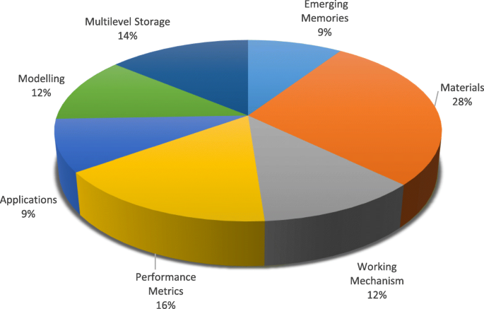
Categoriegewijze distributie van geraadpleegde documenten voor de voorbereiding van een recensie op RRAM
Resistief Random Access Memory (RRAM)
Weerstandschakelmaterialen
Er is waargenomen dat in sommige isolatoren de verandering van weerstand optreedt onder het aanleggen van het aangelegde elektrische veld. Deze eigenschap van verandering van weerstand is onlangs onderzocht voor het ontwikkelen van toekomstige niet-vluchtige herinneringen [17]. Het fenomeen weerstandsschakeling is waargenomen in een verscheidenheid aan oxiden, maar binaire metaaloxiden zijn uitgebreid bestudeerd als een voorkeursschakelmateriaal voor toekomstige niet-vluchtige geheugentoepassingen, voornamelijk vanwege hun compatibiliteit met de CMOS BEOL-verwerking. Verschillende op metaaloxide gebaseerde materialen die de niet-vluchtige weerstandsschakeling vertonen, zoals hafniumoxide (HfO x ) [18–23], titaniumoxide (TiO x ) [24–31], tantaaloxide (TaO x ) [32–36], nikkeloxide (NiO) [37–40], zinkoxide (ZnO) [41–46], zinktitanaat (Zn2 TiO4 ) [47], mangaanoxide (MnO x ) [48, 49], magnesiumoxide (MgO) [50], aluminiumoxide (AlO x ) [51–53], en zirkoniumdioxide (ZrO2 ) [54-58] hebben de meeste aandacht getrokken en zijn de afgelopen jaren uitgebreid bestudeerd. Deze metaaloxiden worden gewoonlijk afgezet door pulslaserafzetting (PLD), atoomlaagafzetting (ALD) en reactief sputteren. ALD is echter een methode die algemeen de voorkeur heeft vanwege het vermogen om de dikte en uniformiteit van de dunne film nauwkeurig te regelen [59].
Bij conventionele elektronische apparaten is de keuze van het elektrodemateriaal belangrijk omdat ze fungeren als transportpaden voor de dragers. Voor RRAM heeft de keuze van het elektrodemateriaal grote invloed op het schakelgedrag van het apparaat. In koper/poly(3-hexylthiofeen):[6,6]-fenyl-C61-boterzuurmethylester/indium-tinoxide (Cu/P3HT:PCBM/ITO) structuur werd bijvoorbeeld een stabiel resistief schakelgedrag waargenomen; het verdween echter nadat de Cu-elektrode was vervangen door Pt-elektrode [60]. Een grote verscheidenheid aan materialen is gebruikt als elektroden voor RRAM. De elektrodematerialen kunnen op basis van hun samenstelling in vijf categorieën worden gegroepeerd, waaronder elektroden van elementaire stoffen, op silicium gebaseerde elektroden, legeringselektroden, oxide-elektroden en op nitriet gebaseerde elektroden. De meest voorkomende en meest gebruikte elektroden zijn elektroden van elementaire stoffen, waaronder Al [51], Ti [49], Cu [30], grafeen [61], koolstofnanobuisjes [62], Ag [41], W [36], en Pt [44]. Voor op silicium gebaseerde elektroden zijn p-type Si en n-type Si [63] de enige typen elektroden die worden gebruikt. Legeringselektroden stabiliseren gewoonlijk het resistieve schakelgedrag en omvatten voornamelijk Cu-Ti [64], Cu-Te[65] en Pt-Al [66]. De meest voorkomende elektroden op nitridebasis zijn de TiN en TaN [67, 68]. De op oxide gebaseerde elektroden zijn relatief overvloedig, waaronder met Al-gedoteerde ZnO [69], Ga-gedoteerde ZnO [70] en ITO [71].
De lijst van metaaloxidematerialen die recentelijk zijn gebruikt bij de fabricage van het RRAM-apparaat, samen met verschillende combinaties van materialen die zijn gebruikt voor de bovenste elektrode en de onderste elektrode, worden weergegeven in tabel 2. Een gedetailleerde vergelijking van de verschillende parameters wordt ook gepresenteerd. Uit de grote verscheidenheid aan gebruikte materialen kan men voorspellen dat de niet-vluchtige weerstandsschakeling op grote schaal wordt waargenomen in verschillende soorten oxiden. De materiaalkeuze voor de fabricage van RRAM geeft het een voorsprong, aangezien metaaloxide-metaal (MOM) structuren gemakkelijk kunnen worden vervaardigd door gebruik te maken van oxiden die momenteel worden gebruikt in de halfgeleidertechnologie. Het materiaal van de onderste elektrode in RRAM is meestal platina, wat een beetje moeilijk te etsen is. Voor een enkele apparaatstructuur kan RRAM dezelfde onderste elektrode delen, terwijl voor de kruisbalkarchitectuur de afzonderlijke onderste elektroden voor elk apparaat worden gebruikt. Ze kunnen worden verkregen door achtereenvolgens fysische dampafzetting en lancering. De bovenste elektrode en de resistieve schakellaag worden afgezet met behulp van atomaire laagafzetting (ALD) of fysieke dampafzetting (PVD).
Weerstandschakelmodi
Een resistief willekeurig toegankelijk geheugen (RRAM) bestaat uit een resistieve schakelgeheugencel met een metaal-isolator-metaalstructuur die in het algemeen wordt aangeduid als MIM-structuur. De structuur bestaat uit een isolerende laag (I) die is ingeklemd tussen de twee metalen (M) elektroden. Het schema en de dwarsdoorsnede van een RRAM-cel worden respectievelijk getoond in Fig. 3a en b.
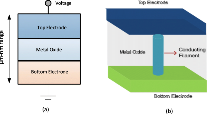
een Schema van metaal-isolator-metaalstructuur voor RRAM. b Dwarsdoorsnede van RRAM
De toepassing van de externe spanningspuls over de RRAM-cel maakt een overgang van het apparaat mogelijk van een hoge weerstandsstatus (HRS), of UIT-status, meestal aangeduid als logische waarde '0', naar een lage weerstandsstatus (LRS), of AAN-status in het algemeen aangeduid als logische waarde '1' en vice versa. Het fenomeen resistive switching (RS) wordt beschouwd als de reden achter deze verandering van weerstandswaarden in een RRAM-cel. Een kant-en-klaar RRAM bevindt zich aanvankelijk in de hoge weerstandstoestand (HRS), om het apparaat van de HRS naar de LRS te schakelen, maakt de toepassing van de hoogspanningspuls de vorming van geleidende paden in de schakellaag mogelijk en wordt de RRAM-cel geschakeld in een LRS [72]. Dit proces dat optreedt als gevolg van de zachte afbraak van de metalen isolator-metaalstructuur (MIM) wordt meestal 'elektrovorming' genoemd en de spanning waarbij dit proces plaatsvindt, wordt vormingsspanning genoemd (V f ). Opgemerkt moet worden dat de vormingsspanning afhankelijk blijkt te zijn van het celoppervlak [73] en de oxidedikte [74]. Om nu de RRAM-cel van de LRS naar HRS te schakelen, wordt de spanningspuls aangeduid als de RESET-spanning (V resetten ) wordt toegepast die deze schakelovergang mogelijk maakt en het proces wordt verwezen naar het 'RESET'-proces [75-78]. De HRS van de RRAM kan worden gewijzigd in LRS bij het aanleggen van de spanningspuls. De spanning waarbij de overgang plaatsvindt van HRS naar LRS wordt SET-spanning genoemd (V instellen ) en het proces wordt het 'SET'-proces [79] genoemd. Om gegevens efficiënt uit de RRAM-cel te lezen, wordt een kleine leesspanning toegepast die de huidige toestand van de cel niet verstoort om te bepalen of de cel zich in de logische 0 (HRS) of de logische 1 (LRS)-status bevindt. Aangezien zowel LRS als HRS hun respectieve waarden behouden, zelfs na het verwijderen van de aangelegde spanning, is RRAM een niet-vluchtig geheugen. Afhankelijk van de polariteit van de aangelegde spanning, kan het RRAM worden ingedeeld in twee soorten schakelmodi:(i) unipolair schakelen en (ii) bipolair schakelen [80]. Bij unipolair schakelen is het schakelen (instel- en resetproces) van het apparaat tussen verschillende weerstandstoestanden niet afhankelijk van de polariteit van de aangelegde spanning, dat wil zeggen dat schakelen kan plaatsvinden bij het aanleggen van een spanning van dezelfde polariteit maar met een verschillende grootte, zoals weergegeven in Fig. 4a. Bij bipolair schakelen daarentegen, is het schakelen (instel- en resetproces) van het apparaat tussen verschillende weerstandstoestanden afhankelijk van de polariteit van de aangelegde spanning, dwz een overgang van een HRS naar LRS, vindt plaats bij één polariteit (positief of negatief) en de tegenovergestelde polariteit schakelt de RRAM-cel terug in de HRS zoals weergegeven in figuur 4b. Bij unipolair schakelen wordt Joule-verwarming geïnterpreteerd als het fysieke mechanisme dat verantwoordelijk is voor het scheuren van een geleidende gloeidraad tijdens het resetten. Bij bipolaire schakeling daarentegen is de migratie van geladen soorten de belangrijkste drijvende kracht voor het oplossen van geleidende filamenten, hoewel Joule-verwarming nog steeds bijdraagt aan het versnellen van de migratie. Om ervoor te zorgen dat er geen permanente storing is van de diëlektrische schakellaag tijdens het vormings-/instelproces van RRAM, een compliantiestroom (I cc ) wordt afgedwongen voor het RRAM-apparaat. De conformiteitsstroom (I cc ) wordt meestal gegarandeerd door een celselectie-apparaat (transistor, diode, weerstand) of door een halfgeleiderparameteranalysator tijdens het off-chip testen.
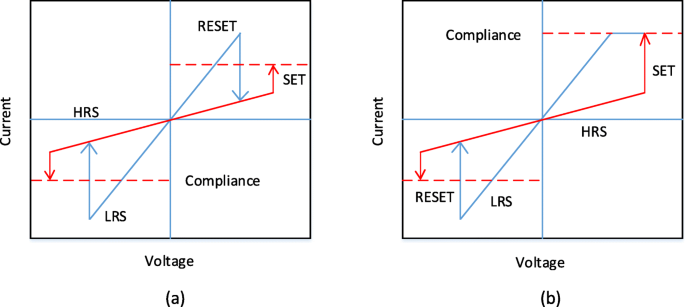
IV-curven voor RRAM. een Unipolair schakelen en b bipolair schakelen [4]
Resistief schakelmechanisme
Het schakelen van de RRAM-cel is gebaseerd op de groei van geleidend filament (CF) in een diëlektricum. De CF is een kanaal met een zeer kleine diameter in de orde van nanometers dat de boven- en onderelektroden van de geheugencel verbindt. Een lage weerstandstoestand (LRS) met hoge geleidbaarheid wordt verkregen wanneer de gloeidraad wordt aangesloten en de hoge weerstand (HRS) ontstaat wanneer de gloeidraad wordt losgekoppeld met een opening tussen de elektroden [91]. Op basis van de samenstelling van de geleidende gloeidraad kan RRAM worden ingedeeld in de volgende twee typen:(i) op metaalionen gebaseerde RRAM, ook wel conductive bridge random access memory (CBRAM) genoemd en (ii) zuurstofvacatures op filamenten gebaseerde RRAM waarnaar wordt verwezen naar als de 'OxRRAM'. Hierbij moet worden opgemerkt dat CBRAM soms wordt aangeduid als het elektrochemisch metallisatiegeheugen (ECM), terwijl 'OxRRAM' soms ook bekend staat als valentieveranderingsgeheugen (VCM).
In op metaalionen gebaseerde RRAM, ook wel 'CBRAM' genoemd, is het fysieke mechanisme dat verantwoordelijk is voor resistief schakelen gebaseerd op de migratie van metaalionen en daaropvolgende reductie/oxidatie (redox) reacties [92, 93]. De CBRAM-structuur bestaat uit een oxideerbare bovenelektrode (anode) zoals Ag, Cu en Ni, een relatief inerte onderelektrode (kathode), b.v. W, Pt en een ingeklemde metaaloxidelaag tussen de twee elektroden. De filamentvorming in dergelijke geheugencellen vindt plaats door het oplossen van de actieve metaalelektroden (meestal Ag of Cu), het transport van kationen (Cu + of Ag + ), en hun daaropvolgende afzetting of reductie op de inerte bodemelektrode [94]. Het resistieve schakelgedrag van dit type RRAM wordt dus gedomineerd door de vorming en ontbinding van de metalen filamenten.
Laten we, om een beter begrip te krijgen van het schakelmechanisme van op metaalionen gebaseerde CBRAM, een voorbeeld bekijken van Ag/a-ZnO/Pt RRAM-cellen [41]. Een algemene schematische illustratie die het schakelproces van een geleidende-brug-geheugencel met willekeurige toegang afbeeldt, wordt getoond in figuur 5. De oorspronkelijke toestand van de CBRAM-geheugencel is afgebeeld in figuur 5a. De Ag-topelektrode (TE) is een actieve component in de filamentvorming, terwijl de onderste Pt-elektrode inert is. Bij de toepassing van de positieve spanningsbias op de Ag-topelektrode, de oxidatie (Ag → Ag + + e − ) komt voor bij de bovenste elektrode waardoor Ag + kationen worden gegenereerd en worden afgezet in de diëlektrische laag (a-ZnO) van de Ag-elektrode. De negatieve bias op de Pt-bodemelektrode (BE) trekt de Ag + . aan kationen, en als zodanig de reductiereactie (Ag + + e − → Ag) komt voor bij de onderste elektrode. Dus de Ag + kationen worden gereduceerd tot Ag-atomen en accumuleren totdat de geleidende brug is gevormd (Fig. 5b-d) en het RRAM-apparaat zou LRS vertonen. Dit proces wordt de ‘SET’ genoemd. Wanneer de polariteit van de aangelegde spanning wordt omgekeerd, lost de sterk geleidende gloeidraad bijna volledig op en bevindt het apparaat zich in de hoge weerstandstoestand (HRS). Dit proces wordt 'RESET' genoemd en wordt weergegeven in Fig. 5e.
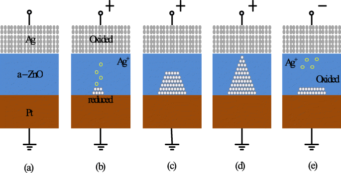
Schema van het schakelmechanisme van geleidende brug RRAM. een Ongerepte staat van het RRAM-apparaat. b , c Oxidatie van Ag en migratie van Ag + kationen naar kathode en hun reductie. d Accumulatie van Ag-atomen en Pt-elektrode leidt tot groei van sterk geleidende gloeidraad. e Het oplossen van het filament vindt plaats bij het aanleggen van een spanning met tegengestelde polariteit [41]
In zuurstofvacature-gebaseerde RRAM (OxRRAM) wordt het fysieke mechanisme dat verantwoordelijk is voor resistief schakelen over het algemeen geassocieerd met het genereren van zuurstofvacatures (V \(_{o}^{2+}\)) en daaropvolgende verplaatsing van zuurstofionen (O 2− ), waardoor de vorming van geleidend filament mogelijk wordt tussen de bovenste en onderste elektroden van de RRAM-cel [59]. Aanvankelijk is voor de als gefabriceerde RRAM-cel het vormingsproces, d.w.z. zachte afbraak van het diëlektricum, essentieel. Zodra de zachte diëlektrische doorslag optreedt, worden de zuurstofatomen uit het rooster geslagen door het aanleggen van een hoog elektrisch veld naar het anode-interface en worden ze zuurstofionen (O 2− ) terwijl de zuurstofvacatures (V \(_{o}^{2+}\)) blijven in de oxidelaag achter. De zuurstofionen (O 2− ) reageren met anodematerialen of ontladen worden als neutrale niet-roosterzuurstof, als de edele metalen worden gebruikt als materialen voor anodes om een grensvlakoxidelaag te vormen. Het elektrode/oxide-interface gedraagt zich dus als een 'zuurstofreservoir' [85]. Vervolgens de accumulatie van de zuurstofvacatures (V \(_{o}^{2+}\)) in het bulkoxide schakelt de RRAM-cel naar de lage weerstandstoestand (LRS) als de geleidende gloeidraad (CF) wordt gevormd en de aanzienlijke stroom in het apparaat vloeit. Om het apparaat terug te schakelen naar de hoge weerstandsstatus (HRS), vindt het resetproces plaats waarbij de zuurstofionen (O 2− ) migreren terug naar bulkoxide van anode-interface en combineren met de zuurstofvacatures (V \(_{o}^{2+}\)) of om de metallische CF-precipitaten te oxideren en zo de gloeidraad gedeeltelijk te scheuren, waardoor de RRAM-cel terugschakelt naar HRS. Voor RRAM-cellen die een unipolair schakelmechanisme vertonen, is de diffusie van zuurstofionen (O 2− ) wordt thermisch geactiveerd door Joule-verwarmingsstroom en als zodanig diffunderen de zuurstofionen uit het grensvlak of het gebied rond de CF als gevolg van de concentratiegradiënt. Ook moet worden opgemerkt dat een relatief hogere resetstroom nodig is in unipolair schakelende RRAM om de lokale temperatuur rond CF te verhogen. Bij bipolair schakelende RRAM daarentegen worden de zuurstofionen (O 2− ) moet worden geholpen door het omgekeerde elektrische veld, aangezien de grenslaag een significante diffusiebarrière kan vormen en pure thermische diffusie niet voldoende is. Opgemerkt moet worden dat de gedeeltelijke breuk van CF in beide gevallen plaatsvindt, waarbij de RRAM-cel in de hoge weerstandstoestand (HRS) wordt geschakeld. Dit komt voornamelijk door de vorming van zuurstofvacatures (V \(_{o}^{2+}\)) en een arm gebied wat resulteert in de tunneling gap voor elektronen. Om het apparaat terug te schakelen naar de LRS (SET-proces), sluit de CF de elektroden weer aan als gevolg van de zachte doorslag in het spleetgebied. Een vergelijkbaar set/reset-proces kan vele cycli herhalen.
Op basis van de bovenstaande discussie vertrouwt CBRAM, ook bekend als elektrochemisch metallisatiegeheugen (ECM), op een elektrochemisch actieve metaalelektrode zoals Ag, Cu of Ni om op metaalkationen gebaseerd CF [95] te vormen. De CF in zuurstofvacatures op filamenten gebaseerd RRAM 'OxRRAM' ook bekend als valentieveranderingsgeheugen (VCM) is samengesteld uit zuurstofvacature-defecten, in plaats van metaalatomen, als gevolg van anionmigratie in het opslagmateriaal zelf [96]. Hoewel het schakelmechanisme van zowel 'OxRRAM' als 'CBRAM' in detail wordt besproken, is er nog steeds enige discussie over de schakelmechanismen van beide RRAM-typen [97]. Bijvoorbeeld waar de CF begint te groeien in het set-proces en waar te breken in het reset-proces, en hoe deze zuurstofvacatures/metaalatomen zich verzamelen om de CF te vormen. De stroom-spanning (I-V) karakteristieken van 20 opeenvolgende schakelcycli van Ta/TaO x /Pt [98]-gebaseerde RRAM-structuur werden onderzocht en de duidelijke variatie van zowel LRS als HRS voor opeenvolgende schakelcycli werd waargenomen. Als gevolg hiervan neemt het totale geheugenvenster af, waardoor de algehele RRAM-prestaties afnemen. Deze weerstandsvariabiliteit van cyclus tot cyclus wordt voornamelijk toegeschreven aan de willekeurige vorming van CF en de breuk ervan tijdens respectievelijk de set- en resetbewerking.
Een vergelijking van OxRRAM met CBRAM op basis van verschillende operationele parameters wordt weergegeven in Tabel 3 [81, 84, 86-88, 99, 100]. Deze vergelijking onthult het opvallende verschil in termen van de duurzaamheidskenmerken van deze RRAM-geheugentypes. Deze ongelijkheid is omdat de geleidende filamenten van CBRAM voornamelijk zijn samengesteld uit metaalatomen die relatief gemakkelijker te driften en diffunderen zijn in vergelijking met zuurstofvacatures, waardoor de retentietijd en uithoudingsvermogen van CBRAM in vergelijking met OxRRAM worden verslechterd. Hoewel het schakelmechanisme van beide RRAM-typen verschillend is, zijn er veel gemeenschappelijke kenmerken tussen de twee. Het enige significante verschil is dat het uithoudingsvermogen voor OxRRAM aanzienlijk hoger is dan voor CBRAM.
Prestatiestatistieken van resistief Random Access Memory (RRAM)
Uithoudingsvermogen
Resistief willekeurig toegankelijk geheugen omvat frequente overgangen tussen een hoge weerstandstoestand (HRS) en een lage weerstandstoestand (LRS). Elke schakelgebeurtenis tussen de resistieve toestanden kan permanente schade veroorzaken en verslechtering van de RRAM-prestaties veroorzaken. Uithoudingsvermogen wordt dus gedefinieerd als het aantal keren dat een RRAM-apparaat kan worden geschakeld tussen de HRS en de LRS, terwijl een betrouwbaar onderscheidbare verhouding tussen beide wordt gegarandeerd [101]. Een duurtest bepaalt dus het maximale aantal set/reset-cycli dat effectief kan worden geschakeld voordat de HRS en de LRS niet langer te onderscheiden zijn. De uithoudingsvermogenkenmerken van RRAM worden verkregen door een reeks IV-sweeps uit te voeren in een resistieve schakelcel en de daaropvolgende extractie van R HRS en R LRS bij het aanleggen van een leesspanning (typisch 0,1 V) [41]. Deze methode is betrouwbaar omdat men de juiste schakeling van het apparaat in elke cyclus kan verkrijgen; deze methode is echter erg traag omdat de tijd die nodig is voor het verkrijgen van een IV-sweep erg hoger kan zijn, vooral als het om lagere stromen gaat.
De uithoudingscycli in een H f O x RRAM-cel vertoont een sterke afhankelijkheid van de celgrootte, zoals weergegeven in figuur 6a, waarin een beter uithoudingsvermogen in een RRAM-apparaat met grotere celgrootte wordt gerapporteerd. Bovendien resulteert het verticaal verminderen van de laagdikte in een verslechtering van de duurzaamheidsprestaties voor SET-spanning bij 2,5 V, zoals weergegeven in Fig. 6b [102]. Deze verslechtering van de uithoudingsprestaties met downscaling van de schakellaag is een gevolg van het verminderde aantal ionen in het actieve gebied. H f O x -gebaseerde RRAM vertoont een uitstekende uithoudingsvermogen van 10 6 cycli op een array van 1 kb met een celgrootte van 30 nm kleiner dan 0,18 μ m-technologie en hetzelfde wordt getoond in Fig. 6c [103]. Door een extra laag A . toe te voegen ik O x boven de onderste elektrode (BE), kan de stabiliteit van de array verder worden verbeterd naarmate de immuniteit voor leesstoringen voor HRS wordt verhoogd. Voor T een O x -gebaseerde RRAM, een verslechtering van de uithoudingsprestaties met toenemende pulsbreedte en amplitude van RESET-spanning werd waargenomen in Ta/Ta2 O5 /TiN RRAM-structuur [105]. Een vergelijking van TiN en Ru bodemelektrode in de Ta/Ta2 O5 /TiN RRAM laat zien dat de belangrijkste oorzaak van achteruitgang van het uithoudingsvermogen te wijten is aan de reactie van zuurstofionen met de TiN-elektrode. Verder een verbeterd uithoudingsvermogen van 10 9 schakelcycli werden verkregen zonder verificatie in een vergelijkbare RRAM-structuur door de Ta2 . te verminderen O5 laag tot 3 nm [106] en gebruik van driehoekige puls met een breedte van <5 ns. Voor grootschalige arrayprestaties is een vergelijking van 2-Mb Ta2 O5 geheugen voor en na 10 5 cycli van duurtest wordt getoond in Fig. 6d [104]. De celstroomverdelingen vertonen een kleine variatie voor de eerste en laatste cycli. Ook daalt de celstroom voor LRS onder 50 μ A, wat wijst op een laag stroomverbruik van de array. De resistieve schakelapparaten met een uithoudingsvermogen hoger dan 10 12 cycles have been reported in different types of RRAM cells involving tantalum oxide (TaO x )-based switching mediums [32, 36, 59]. Thus, tantalum oxide-based RRAM devices seem to be exhibiting the highest endurance.
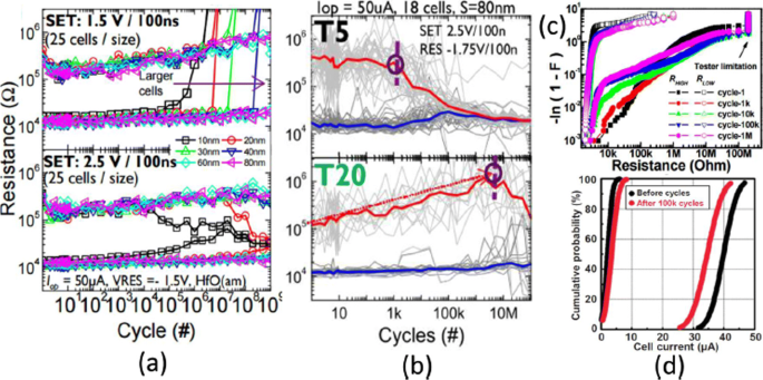
een Endurance cycles of H f O x -based RRAM at different SET voltage and cell size b with different thickness (T5=2 nm, T20=10 nm) at 2.5 V set voltage. c Resistance distribution of 1-kb array obtained from Weibull plots under different endurance cycles. d 100 k cycles endurance of 2-Mb-Ta2 O5 -based array; Reprinted from refs [102–104]
Retention
The data retention of a RRAM device involves investigating stability over a period of time for both LRS and HRS after undergoing set and reset transitions. In other words, the time period for which a memory cell will remain in a particular state after the set/reset operation determines the capability of a memory cell to retain its content [11]. The application of the constant voltage stress (CVS) over time using a low read voltage (0.1 V) and the measurement of the current versus time (I-t) curve for both LRS as well as the HRS enables the measurement of state retention. Due to the dispersing nature of atomic rearrangements induced in RRAM because of set voltage, the long retention time in LRS is difficult to obtain whereas, in HRS, retention is not a concern as it is usually the natural state of the device and RRAM will continue to remain in this state if no bias (or low bias) is applied. The retention in the LRS depends on the compliance limit during the SET transition, e.g. in RRAMs based on conductive filament switching mechanism, the larger compliance current produces a stronger conducting filament which is more stable over time [28, 41], as compared to a smaller compliance current. A projected endurance of 10 years at 85 ∘ C has been demonstrated in Ti/HfO2 /TiN [18]. A commonly used method to obtain device endurance is by applying read pulse at high temperature after certain time intervals (e.g. every 1 s) and extrapolate the resistance to a 10-year period. Although this method is easy to implement, it has certain limitations primarily due to the read voltage stress applied to the cell. An alternative method is to change the temperature and record the time until the device fails. Activation energy is extracted by plotting the Arrhenius plot and extrapolate down to the operating temperature. However, the limitation of this method is that waiting is necessary until the failure occurs in the RRAM cell, and thus, this method is more time-consuming and expensive.
The device characteristics of H f O x -based RRAM [81, 103] developed at the Industrial Technology Research Institute, Taiwan, are demonstrated to further understand the working of RRAM device. The transmission electron microscopy (TEM) image of the TiN/Ti/ H f O x /TiN RRAM device with 30-nm cell size is shown in Fig. 7a. The device exhibits bipolar switching characteristics and the I-V curve obtained at 200 μ A set compliance current is shown in Fig. 7b. The device presents endurance of 10 6 switching cycles with the resistance on/off ratio greater than 100 at set/reset programming conditions of + 1.5 V/– 1.4 V pulse with 500 μ s pulse width and the same is depicted in Fig. 7c.
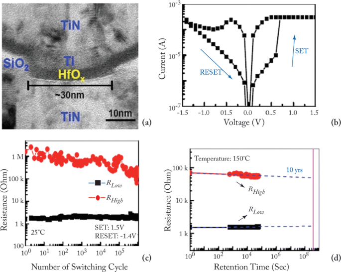
een Transmission electron microscopy (TEM) image of TiN/Ti/HfO x /TiN RRAM device. b Typical current-voltage (I-V) characteristics of the device with 30-nm cell size. c 10 6 endurance switching cycles obtained from 500 μ s pulse. d A retention lifetime of 10 years is expected by testing at 150 ∘ C; reprinted from refs. [81, 103]
Uniformity
In RRAM cell, poor uniformity of various device characteristics is one of the significant factors limiting the manufacturing on a wider scale. The switching voltages, as well as both the HRS and the LRS resistances, are among the parameters exhibiting a high degree of variation. The variations of the resistance switching include temporal fluctuations (cycle-to-cycle) and spatial fluctuations (device-to-device). The stochastic nature of the formation and rupture of conductive filament is believed to be the main reason for these variations. Cycle-to-cycle and device-to-device variability is a major hindrance for information storage in RRAM devices [59]. The observation of cycle-to-cycle variability is influenced by the change in the number of oxygen vacancy defects that arise in the CF due to its stochastic nature of formation and rupture during the switching event [107]. Due to this random nature of the CF, the prediction and the precise control of the shape of the CF becomes extremely challenging. This variability becomes worse as the compliance limit (i.e. compliance current ‘I cc ’) is reduced. On the other hand, for the higher value of ‘I cc ’, the ratio of standard deviation (σ ) and average resistance (μ ) is low, resulting in a smaller LRS resistance spread. This is attributed to the higher defects in the CF, thus forming a well-defined path for current conduction.
RRAM also exhibits device-to-device (cell-to-cell) non-uniformity which also degrades the memory performance by reducing the memory margin between two states. The origin of this variability is attributed to the non-uniformities in the fabrication process such as the thickness of the switching film, etching damages and surface roughness of the electrodes. A lot of research has been conducted to improve the uniformity of RRAM and several methods have been explored for the same. One of the methods utilizes the concept of inserting nano-crystal seeds which confine the paths of the conductive filament by enhancing the effect of local electric field [82, 90, 108]. In Ti/TiO 2−x /Au-based RRAM [28], the induction of platinum (Pt) nano-crystals within the thin TiO 2−x results in an enhanced uniformity of the RRAM cell. The Pt nano-crystals limit the switching effect into regions with high oxygen vacancy generation probability which results in improved uniformity. In another approach, engineering the electrode/oxide interface by embedding appropriate buffer layers is very useful in achieving uniform RRAM operation. In HfO x -based RRAM [109], a thin Al buffer layer is inserted between the TiN electrode and HfO x oxide layer. This results in significant improvement of set voltage distribution as well as the resistance distribution, thus enhancing the uniformity of the device. The improvement in the SET voltage and the resistance distribution of the RRAM device after inserting a thin Al buffer layer between TiN electrode and HfO x bulk oxide and the same is depicted in Fig. 8 [59]. Al atoms are assumed to diffuse into HfO2 thin films, and they tend to localize oxygen vacancies due to the reduced oxygen vacancy formation energy, thus stabilizing the generation of conductive filaments, which helps to improve the resistance switching uniformity.
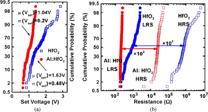
Uniformity improvement of Al buffered HfO x RRAM compared to HfO x -based RRAM array. een Statistical distribution of SET voltage (V instellen ) obtained from 100 DC sweep cycles. b HRS and LRS statistical distribution for 100 pulse sweep cycles; reprinted from ref. [59]
In addition to the materials engineering approach, a novel programming method has also been suggested to reduce fluctuations. A multistep forming technique was implemented in W/HfO2 /Zr/TiN [22]-based RRAM to minimize the overshoot current due to the parasitic effects. A multi-step forming technique results in the gradual formation of the filament; thus, a low set/reset current is achieved improving the switching characteristics of the device. Various other methods such as constant voltage forming and hot forming (usually referred to as forming at a higher temperature) have also been investigated to effectively reduce the resistance variations [110]. Another method of achieving high uniformity is by applying a pulse train rather than a single pulse to a RRAM cell [23]. This approach not only results in improved uniformity but also enhances the multilevel capability of a RRAM cell.
Effect of Operating Temperature and Random Telegraph Noise
To achieve a reliable performance of the RRAM device, the effect of operating temperature and random telegraph noise (RTN) is investigated. It is observed that the resistance of both the LRS and HRS states undergoes variations because of the change of operating temperature. The temperature study of TiN/HfO2 /Ti/TiN [111] was carried out. A positive sweep voltage of <3 V magnitude and compliance current of 1 μ A was applied for the electroforming. Once forming takes place, a reset voltage (V resetten ) <–1 V switches the device back to the HRS (OFF state). To switch the device back to the LRS (ON state), set voltage (V instellen ) <1 V is applied.
The reset operation in RRAM device tends to show voltage-controlled negative differential resistance (NDR). The reset operation occurs abruptly at low temperatures, while for temperatures above room temperature, the reset process takes place more gradually. The resistance of the RRAM device in the pristine state, as well as the ON state and OFF state as a function of temperature is depicted in Fig. 9a. The semiconducting behavior is observed for the pristine state as well as the OFF state, i.e. resistance decreases with increase of temperature. For the ON state, a metallic characteristic is observed, i.e. resistance increases with increase of temperature. Due to the variation of resistance with change in temperature, R OFF /R ON also decreases from a value of 20 to approximately 5 over the temperature range of 213–413K. In Ti/HfO x /Pt devices, decrease in R OFF /R ON was observed with temperature-dependent cycling. This decrease in resistance ratio was attributed to the built-up of oxygen-vacancy-related traps inside the HfO2 metal oxide layer [112, 113]. Additionally, temperature-dependent measurements without set/reset operation were carried out to evaluate the impact of I-V cycling on the R OFF /R ON verhouding. The sweep voltage across the RRAM device was stopped before reaching V instellen en V resetten waarden. For OFF state resistance (green rectangles), a weaker temperature dependence was observed in contrast to the ON state resistance (green circles) which exhibited similar characteristics, compared to the cycling case. From these observations, we infer that I-V cycling induces stronger temperature dependence, which decreases the R UIT /R AAN verhouding. The effect of temperature variation on the switching voltages V instellen en V resetten is depicted in Fig. 9b. The slight variation in V instellen with changing temperature indicates that there is no significant temperature difference. Voor het geval van V resetten , the general trend is that a decrease in voltage value of about 0.2 V with temperature increase in the range of 233–333K is observed. Also, a slow increase of V resetten is observed for 353–413K temperature range.
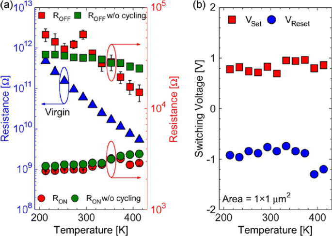
The effect of varying temperature on a virgin resistance (left axis) and the OFF-state as well as the ON-state resistances (right axis) at 213–413K temperature range and b switching voltages V instellen en V resetten; reprinted from ref. [111]
Random telegraph noise (RTN) is another factor that affects the performance of RRAM. RTN has for long been used as an indicator of device performance and reliability. RTN decreases the memory margin between the HRS and LRS because of the extensive fluctuations in the read current during the read operation. Due to the effect of RTN, the read margin, scaling potential and the multilevel cell capability of a RRAM cell are greatly affected [114]; thus, it needs to be investigated to achieve reliable performance. To investigate the effect of bottom electrode on RTN, an analysis of Ta2 O5 /TiO2 RRAM [115] was carried out. The examples of complex RTN signals in LRS and HRS are depicted in Fig. 10. RTN causes read instability in the RRAM device, thus reducing the read margin, multibit storage implementation and hindering device scaling. The RTN is attributed to the trapping and de-trapping of electrons in the proximity of the CF in LRS whereas it occurs in the tunneling gap in the HRS state. Although the physics of RTN is still not clear and is being highly debated, the electron trapping and de-trapping which temporarily inhibits the charge transport is widely accepted as the mechanism responsible for fluctuation due to RTN. It is observed that with the decrease in operation current, the amplitude of RTN increases, thus highly affecting the HRS level. Therefore, it is necessary to ensure the additional resistance margin to achieve reliable performance. RTN in RRAM has been researched extensively, although the physical mechanism of RTN is still not explicitly defined. RTN can be utilized as a tool to map the movements of active vacancies in RRAM due to its time-dependent variation. This might be quite useful to understand the failure mechanisms of other reliability issues.
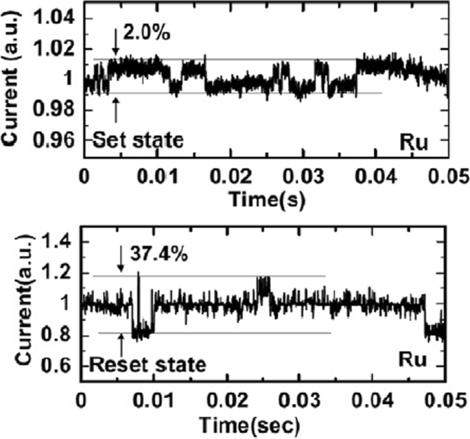
Complex RTN signals in LRS and HRS of Ta2 O5 /TiO2 -based RRAM depicting normalized noise amplitude and average current; reprinted from ref. [114]
Multilevel Resistive Random Access Memory (RRAM)
Multilevel Per Cell (mlc) Storage
Owing to their small physical size and low power consumption, RRAM devices are potential for future memory and logic applications. Increased storage density is among the most critical aspects of memory technology to enable the design of multibit capacity [89] memory cells. The multiple resistive states can be achieved in RRAM cells which provide benefits of low-cost and high-density non-volatile data storage solutions. Currently, a lot of research is being conducted in the area of RRAM to scale down the dimensions and increase the structural density of memory arrays. Previously, the storage density of RRAM has been increased by the reduction of device size; however, the complexity involved in the experimental procedures limits its successful implementation. Another suggested method is employing three-dimensional (3D) crossbar architectures. Two types of architectures of ‘vertical’ and ‘crossbar RRAM’ have been proposed [116, 117]; however, both these architecture types require advanced fabrication procedures which is not desirable. A much simpler alternative to increase storage density in RRAM devices is by making use of multilevel cell (MLC) storage technology which enables storing more than one bit per cell without reducing the physical device dimensions. This MLC is one of the most promising properties of RRAM which can significantly increase the memory storage density [83, 118–125]. Thus, instead of a single high and low resistance state (HRS and LRS), we can achieve multiple HRS and LRS, without changing the device dimensions. However, to achieve reliable MLC operation, the precise control over the resistance of the different resistance levels of RRAM should be ensured; otherwise, the device will suffer from resistance variability and reliability issues mainly due to the random nature of the conductive filament formation during the switching process [126].
Methods to Obtain Multilevel Per Cell (mlc) Modes in RRAM
The MLC behavior in RRAM makes it very useful for high-density applications. To obtain MLC behavior in RRAM, the following three methods are employed:(i) changing compliance current, (ii) controlling reset voltage and (iii) varying pulse width of program/erase operation.
MLC by Changing Compliance Current
The RRAM device is usually operated with 1-RRAM (1R) cell configuration [41] or in 1-Transistor 1-RRAM (1T-1R) cell configuration [18]. The MLC characteristics in 1R configuration can be obtained by changing the current compliance (I cc ) during ‘set’ operation whereas the MLC characteristics in 1-Transistor 1-RRAM (1T-1R) cell structure are controlled by varying the voltage at the gate of the transistor, which enables the control of compliance current (I cc ) during the set operation of a RRAM cell. The typical MLC I-V curves of Ti/Ta2 O5 /Pt [127] based RRAM cell are shown in Fig. 11. As the compliance current (I cc ) is increased from 150 μ A to 1 mA, six different LRS are obtained at I cc =150 μ A, I cc =200 μ A, I cc =300 μ A, I cc =500 μ A and I cc =700 μ A, I cc =1 mA due to the increase in the respective current of LRS (I LRS ) while the HRS is maintained constant and the HRS current (I HRS ) remains same for all the LRS levels. For Ti/Ta2 O5 /Pt RRAM, with the increase in I cc , the maximum reset current (I reset ) also increases while the set voltage is almost maintained constant. Also, it was observed that the resistance of the LRS (R LRS ) decreases while the (I reset ) increases owing to the stronger filament formation with the increase in I cc .
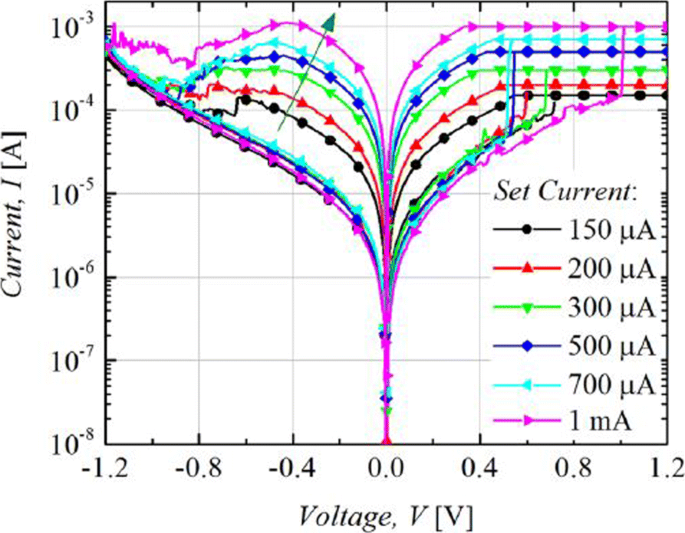
Multilevel characteristics of Ti/Ta2 O5 /Pt RRAM obtained by controlling the compliance current. ‘Reproduced from [127], with the permission of AIP Publishing’
The formation of the CF and its corresponding widening with an increase in I cc is the attributed mechanism of multilevel per cell (MLC) in compliance current (I cc ) mode as depicted schematically in Fig. 12. With an increase in the size of CF because of an increase of I cc , the resistance of the CF decreases and hence results in multiple LRS levels for different values of I cc . It is also observed that I reset increases with increasing I cc as higher power is required to rupture the CF having larger diameter.
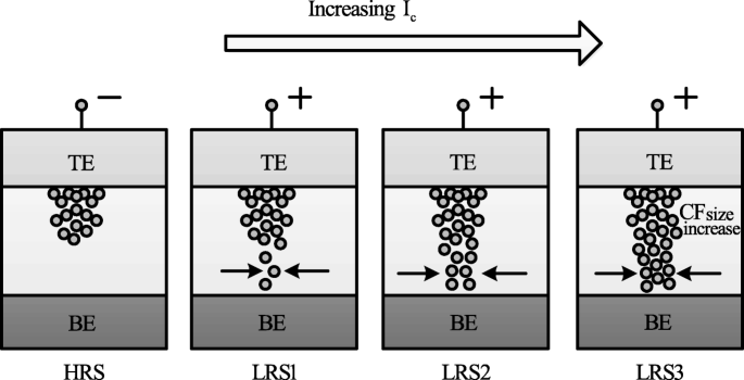
Schematic illustration of multiple resistance states in RRAM cell obtained by varying compliance current ‘I cc ’ [98]
MLC by Controlling Reset Voltage
The MLC characteristics in a RRAM cell can also be obtained by controlling the reset voltage (V resetten ) while (I cc ) is maintained constant. In this case, the typical MLC I-V curves of TiN/HfO x /AlO x /Pt-based RRAM cell [128] by applying different (V resetten ) of − 2.1 V, − 2.7 V and − 3.3 V are shown in Fig. 13.
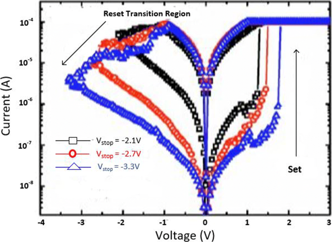
Multilevel characteristics of TiN/HfO x /AlO x /Pt RRAM obtained by controlling the reset voltage. ‘Reproduced from [128], with the permission of AIP Publishing’
It is observed that with an increase in (V resetten ), the HRS current (I HRS ) decreases; thus, multiple HRS levels with the same LRS resistance are obtained. In addition, the set voltage (V instellen ) also increases as V resetten is increased while as the I resetten remains almost constant.
The decrease in I HRS with the increase in reset voltage is primarily due to the increase in the gap between the metal electrode and tip of the CF as depicted in Fig. 14. The more the magnitude of the V resetten , the larger the gap and thus the higher the value of resistance. Therefore, an increase in the gap between the CF tip and bottom electrode (BE) with increasing reset voltage results in multiple resistance levels of HRS. It is observed that the devices in which the I resetten shows a gradual change in current instead of the abrupt change during the ‘reset’ operation, the change in HRS resistance in such devices can be due to decrease in the size of the conductive filament (CF) as V resetten is increased. This approach is more viable practically for cross-point architectures as it requires relatively lower complex circuitry.
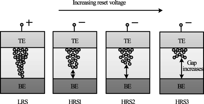
Schematic illustration of multiple resistance states in RRAM cell obtained by varying reset voltage ‘V reset ’ [98]
MLC by Varying Program/erase Pulse Width
MLC characteristics can also be obtained by varying the program/erase pulse width while the amplitude of the pulse is maintained constant [23]. In HfO x -based RRAM [128], three HRS levels were demonstrated by varying the width of the reset pulse from 50 ns to 5 μ s. This method of obtaining MLC characteristics in RRAM is relatively easier; however, this scheme is energy inefficient. This drawback limits the application of this method to obtain reliable characteristics in the RRAM cell. The higher energy consumption of the RRAM device was confirmed on the comparison of the transient responses between the reset pulse amplitude and pulse width control. This is particularly due to the higher unwanted energy dissipation as the thermal energy in the resistive switching material.
A summary of RRAM devices exhibiting multiple resistance states is shown in Table 4. As is evident from the table, various RRAM devices with multiple resistance states have been reported. Till date, however, only 8 resistance states have been demonstrated in a single RRAM cell either by varying I cc or V resetten . Therefore, there is a huge scope for increasing the number of resistance states in the RRAM cell, thus enhancing its storage density.
Modeling of RRAM Devices
Modeling plays a very critical role in development of devices utilizing semiconductor technologies. To fully understand device operation and to optimize the performance, an accurate model is of great importance. A number of RRAM models with varying features and accuracy have been proposed [129]. This section discusses the characteristics and attributes of the various commonly used RRAM models popular.
Stanford/ASU Model
One of the most popular physics-based RRAM models is the Stanford/ASU RRAM model [130–132], proposed by Guan et al. and Chen et al. This model was applied to validate the I-V switching characteristics of HfO2 RRAM [128] and includes the effect of Joule heating and temperature change on the switching of RRAM devices.
This model is dependent on the CF growth inside a dielectric switching layer. The filament gap, i.e. the gap between the tip of the CF and top electrode, is the internal state variable for this model. The growth of CF inside a dielectric is attributed to the oxygen ion movement and regeneration and recombination of oxygen vacancies [133]. Thus, the rate of change of filament gap (g) is given as [130]:
$$ {\frac{dg}{dt}} =V_{\tiny{0}}.\exp\bigg({{\frac{-E_{a},m}{k_{b}.T}} }\bigg). {\text{Sinh}} \bigg({\frac{qa_{h}\gamma V}{L.k_{b}.T}}\bigg) $$ (1)waar E een is the activation energy, V is the magnitude of the voltage applied across the device, L is the switching material thickness, a h is the hopping distance, γ is the local field enhancement factor, V 0 is the velocity containing attempt to escape frequency, K b is de Boltzmann-constante, q is the elementary unit charge and T is the temperature of the conductive filament.
The spatial variation in the gap size is accounted for in this model, in addition to the variations which arise due to the stochastic property of the ion process. A noise signal is added to the gap distance to account for these variations as [130]:
$$ g_{|t+\Delta t} =F \Big[ g_{|t}, {\frac{dg}{dt}} \Big] + \delta_{g}\times\tilde{X}(n)\Delta t, n ={\frac{t}{T_{GN}}} $$ (2)waar Δ t is the simulation time step, the function F represents time evolution of gap size fromt to Δ t. \(\tilde {X}\)(n) is a zero mean Gaussian noise sequence. T GN is the time interval after which \(\tilde {X}\)(n ) changes to next random value.
The variation in the gap size δ g depends on kinetic energy of ions and filament temperature as [130]:
$$ \delta_{g} (T) ={\frac{\delta^{\tiny{0}}_{g}}{\bigg\{ 1+\exp \Big({\frac{T_{\text{crit}}- T}{T_{\text{smith}}}} \Big) \bigg\}}} $$ (3)where \(\delta ^{0}_{g}\) and T smith are fitting coefficients to match the resistance distribution curves to experiments and T crit is a threshold temperature above which the gap size changes significantly.
This model shows strong dependence on temperature; thus, there is a need to account for the change of ‘T’ . With change in cell characteristics, the dynamic inner domain temperature T changes significantly, while the outer domain assumed to be at uniform and stable temperature (T bath ), is related as [130]:
$$ c_{p} {\frac{dT}{dt}} =V(t).I(t) - k(T-T_{\text{bath}}) $$ (4)where C p is the effective heat capacitance of inner domain, V (t) I (t) represents the Joule heating and k is the effective thermal conductivity.
Using a generalized conduction mechanism, the current conduction is defined as [130]:
$$ I(g,v) =I_{\tiny{0}}.\exp\bigg({{\frac{-g}{g_{\tiny{0}}}} }\bigg){\text{Sinh}} \bigg({\frac{V}{V_{\tiny{0}}}}\bigg) $$ (5)waar ik 0 , g 0 en V 0 are the fitting parameters to match experimental results.
One of the significant features of this model is its implementation in neuromorphic applications and RRAM synaptic device design [134], giving the model a great degree of flexibility and further scope for implementation in various neuromorphic systems.
Physical Electro-thermal Model
Physical electro-thermal model was developed by Kim et al. [135] and implemented with tantalum pentoxide (Ta2 O5 ) -based bilayer RRAM [136–138]. This physical model solves the differential equations based on finite element solving method. This model also makes use of electrothermal physics phenomenon approach for modeling [139], thus giving it advantage in terms of flexibility to incorporate finite element method (FEM) solver to simulate the system very accurately. However, the drawback of this approach is its difficulty in implementation for SPICE and Verilog circuit solvers.
This model describes CF as a doped region having oxygen vacancies as dopants with CF extending from the top to the bottom electrode of the device. To describe the drift-diffusion of vacancy migration, this model assumes the same equation can be used to describe both the processes of oxygen ions and vacancies. The ion model by Mott and Gurney [140] is employed here to describe the process given as [135]:
$$ {\frac{dn_{D}}{dt}} =\Delta \times \bigg(D_{s}.\Delta_{n\tiny{D}}- \mu v n_{D} \bigg) + G $$ (6)waar D s describes the diffusion process, v gives the drift velocity of vacancies and G is the CF growth rate which actually describes the SET process. The parameters are defined as [135]:
$$ D_{s} ={\frac{1}{2}} \times a^{2} \times f_{e} \times \exp \bigg({\frac{- E_{a}}{k_{B}T}} \bigg) $$ (7) $$ v =a_{h} \times f \times \exp \bigg({\frac{- E_{a}}{k_{B}T}} \bigg) \times {\text{Sinh}} \bigg({\frac{q a_{h}E}{k_{B}T}} \bigg) $$ (8) $$ G =A \times \exp \bigg({\frac{- (E_{a}-ql_{m}E)}{k_{B}T}} \bigg) $$ (9)where l m is the mesh size.
These equations govern the physical transformation of the device during SET and RESET transition, thus essentially controlling the CF growth and rupture.
Huang’s Physical Model
Huang’s physical model developed by Huang et al. [141, 142] is a very comprehensive physical model for RRAM device as it takes into account both the CF width and the gap of filament to electrode as the factors affecting the state variable dynamics. In addition, temperature distribution is also accounted for in this model.
SET/RESET process is considered as a result of generation/recombination process of oxygen ions (O 2− ) and oxygen vacancies (V 0 ). During the SET process, CF starts to evolve from the tip of the top electrode (T.E) and elongates in radius with increase in voltage, resulting in final width ‘W’ of the C.F. This model assumes symmetrical cylindrical shape of the C.F. During RESET process, CF ruptures starting from TE till it dissolves completely with increase in voltage. The filament gap distance ‘x’ is defined as the gap between active electrode layer (T.E) and the tip of the C.F.
Thus, for the SET process, parameter ‘W’ acts as state variable, while for RESET, parameter ‘x’ acts as state variable. Therefore, \(\frac {dx}{dt}\) and \(\frac {dw}{dt}\) define the dynamics of the device during the SET/RESET transition.
During the first reset process, CF reduction rate, i.e. release of O 2− , is by the electrode is expressed as [142]:
$$ {\frac{dx}{dt}} =a \times f\times \exp \bigg({\frac{- E_{i}-\gamma Z_{e}V}{k_{B}T}} \bigg) $$ (10)For O 2− hopping within the oxide layer, the CF reduction rate with ‘a’ being the distance between two V0 is given as [142]:
$$ {\frac{dx}{dt}} =a \times f\times \exp \bigg({\frac{- E_{h}}{k_{B}T}} \bigg) {\text{Sinh}} \bigg({\frac{ a_{h}Z_{e}E}{k_{B}T}} \bigg) $$ (11)For the case of RESET process when dominated by recombination between O 2− and V0 is expressed as [142]:
$$ {\frac{dx}{dt}} =a \times f\times \exp \bigg({\frac{- \Delta E_{r}}{k_{B}T}} \bigg) $$ (12)In the initial step of the SET process dominated by recombination of oxygen vacancies with thin CF initially grown is given by [142]:
$$ {\frac{dx}{dt}} =-a \times f_{e}\times \exp \bigg({\frac{- E_{a}-\alpha_{a} Z_{e}E}{k_{B}T}} \bigg) $$ (13)Here, Z en α g are the fitting parameters.
For the second step, CF grows along its radial direction and is defined as [142]:
$$ {\frac{dw}{dt}} =\bigg(\Delta w + {\frac{\Delta w^{2}}{2w}} \bigg) \times f_{e}\times \exp \bigg({\frac{- E_{a}-\gamma Z_{e}v}{k_{B}T}} \bigg) $$ (14)The current flowing through the device is modeled as a correlation of hopping current with voltage and gap distance expressed by [134] as:
$$ i =i_{0}. \exp \bigg({\frac{-x}{x_{T}}} \bigg) {\text{Sinh}} \bigg({\frac{v}{v_{T}}} \bigg) $$ (15)This model is validated in HfO x /TiO x system [141, 142], and a pretty accurate match between the experimental and simulation results is obtained. Although this model accounts for the significant processes which affect the RRAM operation, however, it has some limitations. The most critical one is being incompatible with the SPICE and Verilog-A.
Filament Dissolution Model
This model was developed exclusively for unipolar RRAM devices by Russo et al. [143–145], however was later modified for bipolar RRAM devices [139, 146] also. Filament dissolution model is based on rupture of CF under the effect of significant temperature change caused due to Joule heating.
One of the significant advantages of this model is that it utilizes the simple partial differential equations to account for the device current and temperature changes due to Joule heating as well as the dissolution velocity. The conduction of current within the device is described by Poisson’s equation [144] as:
$$ \triangledown \times \bigg({\frac{1}{\varphi}\triangledown_{v}} \bigg) =0 $$ (16)Here, φ is the oxide resistivity and v defines the electric potential due to the application of external bias voltage to one of the electrodes while the other electrode is connected to ground.
The CF is divided into a number of mesh grids and at each point of the mesh grid the temperature is calculated to describe the rupture of CF. The Fourier steady-state heat equation describes this effect as [144]:
$$ -\triangledown \times \bigg(k \triangledown T \bigg) =\varphi J^{2} $$ (17)waar k represents the oxide layer thermal conductivity, J is the current density and T is the device temperature.
The temperature ‘T’ of the device increases to the critical temperature, after which the device is reset and the CF dissolution takes place. The dissolution factor is modeled as [144]:
$$ V_{\text{DIS}} =V_{\text{DIS}-F}. \exp \bigg({\frac{- E_{a}}{k_{B}T}} \bigg) $$ (18)waar E een is the activation energy, k b is the Boltzmann constant, V DIS−F is a fitting parameter and V DIS is velocity of CF boundary towards symmetry axis.
The resistivity of CF is temperature-dependent and is described as [144]:
$$ \varphi_{\text{CF}} (T) =\varphi_{\mathrm{CF-RT}} \Big[ 1 + C (T-T_{0}) \Big] $$ (19)waar C is the experimentally calculated temperature coefficient of resistivity and φ C F −R T is the standard CF resistivity at room temperature.
COMSOL Multiphysics Software [147] is used for solving the coupled equations for this RRAM model due to its multiphysics capabities and ability to handle such simulations.
Bocquet Bipolar Model
Bocquet bipolar model [148] describes the bipolar oxide-based resistive switching memories utilizing a physics-based modeling approach. Bocquet bipolar model describes the electroforming process of RRAM device, inaddition to utilizing some of the characteristics from Bocquet unipolar model [149] and modifies them significantly according to the bipolar switching characteristics. In this model, the radius of the CF is the internal state variable which effectively governs the switching rate.
To model the electroforming stage, Bocquet bipolar model utilizes electroforming rate (τ Form ) which details the mechanism of conversion to switchable sub-oxide from pristine oxide. The electroforming stage is modeled as [148]:
$$ \tau_{\text{form}} =\tau_{\text{form}0} \times \exp \bigg({\frac{E_{a\text{Form}}-q \times \alpha_{s} \times V_{\text{cell}}}{k_{B}\times T}} \bigg) $$ (20) $$ {\frac{dr_{\text{CFmax}}}{dx}} ={\frac{r_{\text{work}}-r_{\text{CFmax}}}{\tau_{\text{form}}}} $$ (21)waar E een Form is the activation energy for electroforming, τ form0 is the nominal forming rate, α s is the charge transfer coefficient, V cell is the voltage applied between the top and bottom electrodes, r CF is the radius of CF which varies from 0 to r CFmax , q is the elementary charge of electron, T is the temperature of the device and k B is the Boltzmann constant.
The electrochemical redox reaction derived from Butler-Volmer equation [150] is used to describe the SET/RESET operation as [148]:
$$ \tau_{\text{Red}} =\tau_{\text{Redox}} \times \exp \bigg({\frac{E_{a}-q \times \alpha_{s} \times V_{\text{cell}}}{k_{B} \times T}} \bigg) $$ (22) $$ \tau_{Ox} =\tau_{\text{Redox}} \times \exp \bigg({\frac{E_{a}+q \times (1 - \alpha_{s}) \times V_{\text{cell}}}{k_{B} \times T}} \bigg) $$ (23)Here, τ Red en τ Ox are the reduction and oxidation rates, respectively. τ Redox is the effective reaction rate considering both reduction and oxidation reactions.
The switching rate is obtained by coupling the above two equations as [148]:
$$ {\frac{dr_{CF}}{dt}} ={\frac{r_{\text{CFmax}}-r_{\text{CF}}}{\tau_{\text{red}}}} - {\frac{r_{\text{CF}}}{\tau_{\text{Ox}}}} $$ (24)Bocquet bipolar model is a quite comprehensive model as it includes the temperature effects as well. The local filament temperature is coupled using heat equation and is given in Eq.(25), the temperature considering a cylindrical-shaped filament is given in Eq. (26). The maximum temperature reached into CF at x =0, the middle of the filament is given in Eq. (27) and the equivalent electrical conductivity in the work area (σ eq ) is given in Eq. (28).
$$ \sigma_{x} \times F(x)^{2} =- k_{th}.{\frac{d^{2}T(x)}{dx^{2}}} $$ (25) $$ T(x) =T_{\text{amb}}+{\frac{V^{2}_{\text{cell}}}{2. L^{2}_{x}.k_{th}}} \bigg({\frac{L^{2}_{x}}{4}- x^{2}} \bigg) \sigma_{eq} $$ (26) $$ T =T_{\text{amb}}+{\frac{V^{2}_{\text{cell}}}{8. k_{th}}} \sigma_{eq} $$ (27) $$ \sigma_{eq} =\sigma_{CF}.{\frac{r^{2}_{\text{CF}}}{r^{2}_{\text{work}}}} - \sigma_{Ox}. {\frac{r^{2}_{\text{CFmax}}-r^{2}_{\text{CF}}}{r^{2}_{\text{work}}}} $$ (28)where (σ x ) is the local electrical conductivity, F (x ) is the local electric field, σ CF is the electrical conductivity of the conductive filament, k de is the thermal conductivity and T amb is the ambient temperature.
It must be mentioned here that temperature increases with increase in radius of the CF, resulting in self-accelerated reaction due to a positive feedback loop. The self-limited reaction also referred to as SOFT reset [151], on the other hand, occurs due to the decrease in temperature and radius of the CF during RESET operation.
The total current flowing in OxRRAM is the sum of currents flowing in the conductive area (I CF ), the conduction through switchable sub-oxide (I sub−oxide ) and conduction through unswitched pristine oxide (I pristine ). The total current is as [148]:
$$ I_{\text{cell}} =I_{\mathrm{sub-oxide}} + I_{\text{CF}} + I_{\text{Pristine}} $$ (29) $$ I_{\text{CF}} =F.\pi. \sigma_{CF}.r^{2}_{CF} $$ (30) $$ I_{\mathrm{sub-oxide}} =F.\pi. \sigma_{Ox}. \big(r^{2}_{\text{CFmax}}- r^{2}_{CF}\big) $$ (31) $$ I_{\text{Pristine}} =S_{cell}.A.F^{2}. \exp {\frac{-B}{F}} $$ (32) $$ A ={\frac{m_{e}.q^{3} }{8\pi.h.m^{ox}_{e}.\phi_{b} }} $$ (33)The parameter B e is the metal-oxide barrier height (ϕ b )-dependent and is given as [148]:
$$ if \phi_{b}\geq qL_{x}F:B_{e} ={\frac{8 \pi \sqrt{2m^{ox}_{e} }}{3\times h\times q}} \Big[ \phi^{{\frac{3}{2}}}_{b}- (\phi_{b}-qL_{x}E)^{{\frac{3}{2}}} \Big] $$ $$ \text{otherwise}, B_{e} ={\frac{8 \pi \sqrt{2m^{ox}_{e} }}{3\times h\times q}} \times \phi^{{\frac{3}{2}}}_{b} $$ (34)where m e and \(m^{ox}_{e}\) are the effective electron masses into the cathode and oxide respectively, F =\(\frac {V_{\text {cell}} }{L_{x}}\) is the electric field across the active layer, h is the Planck constant and S cell is the section of the RRAM cell.
Discrete solutions are required to implement the model in an electrical simulator. This model accounts well in that aspect, making it suitable for simulation involving electrical circuits. This model implements equations in Eldo circuit simulator [152]. The discrete solutions are given as [148]:
$$ r_{\text{CFmax}_{i+1}} =\big(r_{\text{CFmax}_{i}}- r_{\text{work}} \big) \times e^{ {\frac{-\Delta t}{{\tau}_{\text{form}}}} } + r_{\text{work}} $$ (35) $$ r_{CF_{i+1}} =\bigg(r_{CF_{i}}- r_{\text{CFmax}_{i}} \times {\frac{\tau_{eq}}{\tau_{\text{Red}}}} \bigg) \times e^{ {\frac{-\Delta t}{{\tau}_{eq}}} } + r_{\text{CFmax}_{i}} \times {\frac{\tau_{eq}}{\tau_{\text{Red}}}} $$ (36) $$ \text{where} { \tau_{eq}} =\frac{\tau_{\text{Red}}\times \tau_{\text{Ox}} }{\tau_{\text{Red}}+\tau_{\text{Ox}}} $$ (37)This model has been verified against electrical characterization from an HfO2 -based system [153]. An important feature of this model is that it can account effectively for device to device variability [154, 155]. One of the major limitations of this model is the lack of current or voltage threshold.
This section presents in detail various characteristics and features of the RRAM models. A comparative analysis of the RRAM models discussed in this work is presented in Table 5.
Applications of RRAM
RRAM is seen as one of the standout candidates among the emerging memory technologies that has the potential for reforming the memory hierarchy primarily due to its high speed, the capability of non-volatile data storage, enhanced storage density and logic computing function. The various novel applications of RRAM are discussed in this section.
>Non-volatile Logic
The instruction codes and the data are transferred by making use of buses between various units in a computer system having von Neumann architecture because of the separate computing and memory unit. This data transferring process results increased energy consumption and time delay, which is commonly referred to as ‘von Neumann bottleneck’. For reducing the impact of von Neumann bottleneck [156], the computing process which utilizes RRAM crossbar array is suggested which alters the memory and computing operations in the same core. In addition, to obtain high integration density and low cost [157], two-terminal compact device structure of RRAM and its 4F 2 array architecture are highly beneficial. For example, to obtain simple Boolean logic functions such as ‘logic NOT’, ‘logic AND’, and ‘logic OR’, we require multiple transistors and each single transistor takes 8−10F 2 Oppervlakte. These logic functions can be realized by making use of two or three RRAM cells, resulting in total approximate area of around 10F 2 only [158].
Till date, several methods have been suggested for realizing Boolean logic functions [159, 160]. Boolean computing is significantly more established compared to existing non-Boolean computing paradigms such as neuromorphic computing and quantum computing. Therefore, energy and cost-efficiency of CPU or MCU can be enhanced without the need to develop new algorithms or software, although there is still a lack of technical solution on how to implement complex computing tasks in a crossbar array. Thus, most of research to date focusses on only basic logic level demonstration as it becomes quite complex to implement a whole computing unit using RRAM array.
Neuromorphic Computing
To overcome ‘von Neumann bottleneck’, one of the effective ways is brain-inspired neuromorphic computing which has shown promising potential in a wide range of complex and cognitive tasks like visual/audio recognition, self-driving, and real-time big-data analytics. Compared to CMOS-based neuromorphic network, neuromorphic computing based on RRAM-array offers advantages in terms of on-chip weight storage, online training, and scaling up to much larger array size [161–163]. In addition, the processing speed of RRAM improves by three orders of magnitude, whereas the power consumption rate is reduced by four orders of magnitude [164].
For realizing hardware-implemented neuromorphic computing paradigms, two methods are suggested:one among the strategies mimics the structure and working mechanism of biological neural networks while the other method works on accelerating the existing artificial neural network (ANN) algorithms. In a neural network, a synapse is used to transfer spikes between different neurons in addition to storing information about the transferring weights. The information regarding weights can be acquired through certain learning rules such as spike-time-dependent plasticity (STDP) and spike-rate-dependent plasticity (SRDP) [165–167]. Although some of the works reported in the literature have tried to emulate such learning rules on RRAM devices, it is however quite complicated to extend such types of bioinspired learning rules to a complex task as the theoretical algorithm is still lacking.
A practically viable approach is to map an ANN to a RRAM-based neuromorphic network directly. Some advanced tasks such as pattern and speech recognition have been demonstrated based on this method [166–169]. Although very promising, RRAM-based synapse is still far from being applied as various issues such as material optimization, variation suppressing, control circuit design, architecture, and algorithms design for analog computing need to be addressed effectively.
Security Application
The security aspect has become more prominent with rapid developments in the field of information technology; thus, there is a need for hardware-based security-integrated circuits. In contrast to security circuits based on CMOS logic which exploits the random nature of the semiconductor manufacturing process, security circuits based on RRAM are more robust to attacks of various types due to its completely random switching mechanisms [170, 171]. It must be noted that for security applications, larger variation of RRAM device parameters such as random telegraph noise (RTN), resistance variations and probabilistic switching is desirable, which is quite different from memory applications that require a smaller degree of variation among numerous parameters.
A novel security feature commonly referred to as physical unclonable function (PUF) [172], based on RRAM is proposed for device authentication (strong PUF) and key generation (weak PUF) applications. Significantly larger number of input-output pairs [also called challenge-response pair (CRP) are required for strong PUF, while only a small amount of CRPs of extremely higher reliability are required for weak PUF [173]. Although, PUFs based on RRAM have demonstrated remarkable performance; however, still more practical demonstrations and further evaluations are required to work out the maturity of this new primitive within the field of hardware security.
Non-volatile SRAM
Volatile memory technologies like SRAM and DRAM may consume over half of the static power within the current mobile SoC chips. Thus, to attain fast parallel memory operations, reduced area and low-energy consumption, RRAM-based non-volatile SRAM (nvSRAM) was proposed [174] in which two RRAM cells are stacked on eight transistors, forming an 8T2R structure. Also, non-volatile ternary content-addressable memory (TCAM) having 4T2R cell structure [175] and non-volatile flip flops having reduced stress time and write power based on RRAM have been demonstrated recently [176].
Challenges and Future Outlook
During the past several years, research in the field of emerging memory technologies has grown significantly and several prototype RRAM products have been developed demonstrating the potential for high-speed and low-power embedded memory applications. RRAM is one of the most promising memory technologies because of the advantages of simple structure, compatibility with the existing CMOS technology, good switching speed and ability to scale to the smallest dimensions. As a matter of fact, currently the Flash memory technology is facing difficulties to reduce to lower dimensions and as such RRAM is emerging as a potential replacement especially for fast operation and medium size storage density memory applications.
One of the most critical aspects that needs to be thoroughly investigated is that of the reliability of RRAM. A mechanism must be developed to ensure the detection of the operation failure of the device. Also designing circuits, e.g. a test element group (TEG) design for robust signal sensing, is one of the critical challenges for the emergence of RRAM devices. To achieve high-density memory operation in RRAM, the 1D1R operation is essential. This can be realized by operating the RRAM device in the unipolar mode. However, in the unipolar operation, higher current is needed for the reset process as compared to that of the bipolar operation. This is due to the fact that thermal effect plays a significant role in the unipolar reset process. Thus, to realize a high-density 1D1R RRAM array, the thermal effects both inside and outside a memory element needs to be considered. Also note that till date, in a single RRAM device, no technology has simultaneously reported fast switching, low power, and stable operation. Although, the endurance of RRAM has been reported as high as 10 12 [59], it is still not enough to be able to replace DRAM. The RRAM possesses the switching speed fast enough for DRAM replacement and the materials used in the fabrication for RRAM are very similar to that of DRAM, it becomes a critical challenge to improve the endurance characteristics of RRAM. To improve the endurance characteristics, it is necessary to control the oxygen movement between the electrode and the oxide layer at the interface. It is suggested to insert the second metal layer at the interface which can be easily oxidized and acts as an oxygen reservoir to prevent oxygen from penetrating into the electrode during the resistance switching. The most critical challenge hindering RRAM development till date is the proper understanding of the device switching mechanism which is since long being debated by researchers across the globe. The inconsistent switching mechanism of various reported RRAM devices is believed to be because of variation in the fabrication process, and thus, more rigorous analysis is needed in the future for obtaining a better understanding of the switching mechanism of RRAM devices. The aforesaid issues need to be handled effectively before implementing RRAM in future memory applications. Although, RRAM is highly attractive for use in neuromorphic computations, the biggest challenge to industrialize RRAM lies in its ability to tackle the variability issues, not only at nominal operating conditions but also at high temperatures before they can be used in a wide variety of applications.
Conclusion
This review article provides a brief introduction into the advancement of the memory architecture, the current trends and the limitations while providing a valuable insight into the field of emerging memory technologies. A detailed discussion, highlighting the importance of RRAM, its structure, working mechanism, and classification, has been presented. The key performance parameters and their effect on the RRAM operation has also been detailed within the current manuscript. An elaborate study on the MLC capability of RRAM, along with the methodology have been presented. The manuscript also discusses the important features of the widely accepted RRAM models. The implementation of RRAM for various important applications such as non-volatile logic, neuromorphic computing, security, and non-volatile SRAM have been highlighted. Although, significant success has been achieved in RRAM technology; however, more work is needed as RRAM still suffers from various challenges in terms in terms of high operation current, lower resistance ratios, and reliability issues. More efforts in research should aim to develop methods to achieve faster programming/erasing, lower power consumption, enhancing the storage density by implementing multilevel storage capability and improvement in the fabrication process for enhanced uniformity. In addition, renewed focus should be towards use of RRAM in embedded memory and non-volatile logic applications as breakthroughs in these fields are much more exciting and significant. With continued work and improvements, it is imperative that RRAM devices will be a standout technology for future non-volatile memory applications.
Beschikbaarheid van gegevens en materialen
Niet van toepassing.
Afkortingen
- RRAM:
-
Resistive random access memory
- MLC:
-
Multilevel cell
- RTN:
-
Random telegraph noise
- DRAM:
-
Dynamic random access memory
- SRAM:
-
Static random access memory
- PCM:
-
Phase change memory
- STT-MRAM:
-
Spin-transfer torque resistive random access memory
- LRS:
-
Low resistance state
- HRS:
-
High resistance state
- MTJ:
-
Magnetic tunneling junction
- MIM:
-
Metaal-isolator-metaal
- MoM:
-
Metal-oxide-metal
- PLD:
-
Pulse laser deposition
- ALD:
-
Atoomlaagafzetting
- V set :
-
Set voltage
- V reset :
-
Reset voltage
- V f :
-
Forming voltage
- Ik CC :
-
Compliance current
- CBRRAM:
-
Conductive bridge resistive random access memory
- OxRRAM:
-
Oxygen vacancies resistive random access memory
- ECM:
-
Electrochemical metallization memory
- VCM:
-
Valence change memory
- CF:
-
Conductive filament
- BE:
-
Bottom electrode
- TEM:
-
Transmissie-elektronenmicroscopie
- I-V:
-
Stroom-spanning
- 1T-1R:
-
1-Transistor 1-RRAM
- ANN:
-
Artificial neural network
- STDP:
-
Spike-time-dependent plasticity
- SRDP:
-
Spike-rate-dependent plasticity
- PUF:
-
Physical unclonable function
- CRP:
-
Challenge-response-pair
- nvSRAM:
-
Non-volatile SRAM
- TCAM:
-
Ternary content addressable memory
- TEG:
-
Test element group
Nanomaterialen
- 13 soorten vuurvaste materialen en hun toepassingen
- Verbeteren van prestaties en beveiliging in IoT-wearables
- Cervoz:de juiste flash-opslag kiezen voor industriële toepassingen
- Bipolaire resistieve schakelkenmerken van HfO2/TiO2/HfO2 drielaagse structuur RRAM-apparaten op Pt- en TiN-gecoate substraten vervaardigd door atomaire laagafzetting
- Compliance-vrij ZrO2/ZrO2 − x /ZrO2 resistief geheugen met controleerbaar interfaciaal multistate schakelgedrag
- Een RRAM-geïntegreerde 4T SRAM met zelfremmende resistieve schakelbelasting door puur CMOS logisch proces
- Geleidingsmechanisme en verbeterd uithoudingsvermogen in HfO2-gebaseerd RRAM met nitridatiebehandeling
- Een collectief onderzoek naar modellering en simulatie van resistief willekeurig toegankelijk geheugen
- Hiërarchisch macroporeuze grafische nanowebs die ultrasnelle en stabiele laadopslagprestaties vertonen
- Synthese en supercondensatorprestaties van met polyaniline/stikstof gedoteerde mesoporeuze koolstofcomposieten
- Een onderzoek naar de variabiliteit in contactresistief willekeurig toegankelijk geheugen door stochastisch vacaturemodel


