


3D-printtypen:7 hoofdcategorieën van 3D-printtechnologieën
Wanneer de meeste mensen ‘3D-printen’ horen, stellen ze zich een kleine desktopmachine voor die plastic onderdelen maakt. Maar achter de schermen gebeurt er nog veel meer. Wat wij 3D-printen noemen, is eigenlijk een groep verschillende technologieën die objecten laag voor laag opbouwen vanuit een digitaal ontwerp.
In tegenstelling tot traditionele productie, waarbij materiaal uit een massief blok wordt gesneden, voegen 3D-printers alleen toe wat nodig is.
Volgens de ISO/ASTM 52900-15-standaard is 3D-printen onderverdeeld in zeven categorieën:vatfotopolymerisatie, materiaaljetting, bindmiddeljetting, poederbedfusie, materiaalextrusie, gerichte energiedepositie en plaatlaminering. Elk van deze gebruikt een andere aanpak en elk heeft zijn eigen sterke punten, afhankelijk van de materialen waarmee u werkt, uw budget en hoe complex uw onderdeel is.
Enkele van de meest geavanceerde 3D-printmethoden van vandaag gaan helemaal terug tot de jaren tachtig. Stereolithografie (SLA) werd in 1986 gepatenteerd en sindsdien hebben we enorme doorbraken gezien, zoals FDM, SLS en MJF, elk ontworpen voor verschillende doeleinden:snelheid, detail, materiaalbereik of kostenefficiëntie.
Je kunt nu desktopmachines vinden voor minder dan $ 200 en industriële systemen die meer dan $ 1 miljoen kosten. Van PLA en ABS tot metaalpoeders, keramiek en fotopolymeerharsen:de 3D-printindustrie is uitgegroeid tot een serieus hulpmiddel voor zowel hobbyisten als productie-ingenieurs.
In dit artikel bespreken we alle belangrijke soorten 3D-printen, onderzoeken we hoe ze werken en helpen we je erachter te komen welke het beste bij je behoeften past, of je nu net begint of de productie aan het opschalen bent.
Materiaalextrusie
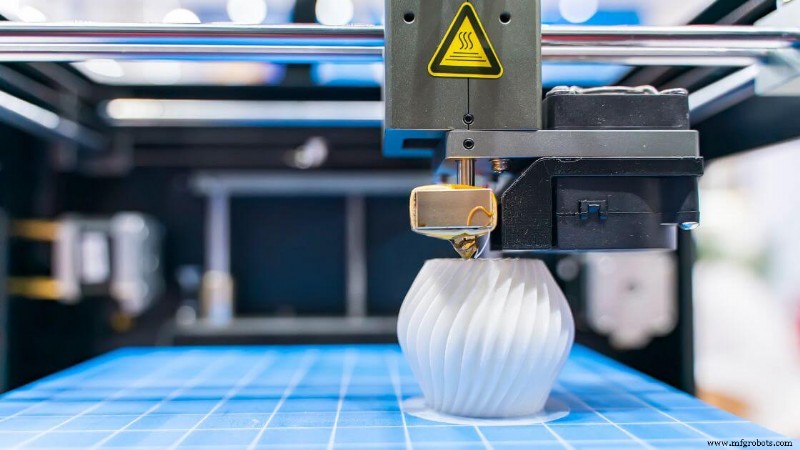 Materiaalextrusie verwijst naar een groep 3D-printprocessen waarbij bouwmateriaal door een mondstuk wordt geduwd en laag voor laag wordt neergelegd om een driedimensionaal onderdeel te vormen.
Het materiaal, meestal thermoplastisch, wordt verwarmd tot het halfvloeibaar is en vervolgens geëxtrudeerd in een gecontroleerd pad, geleid door een computerondersteund ontwerpbestand. Elke laag versmelt met de vorige terwijl deze afkoelt, waardoor een stevige structuur ontstaat.
Dit is een van de meest voorkomende en toegankelijke vormen van 3D-printmethoden. Je ziet het vaak bij desktop 3D-printers die spooled filament gebruiken, maar de categorie omvat ook machines met hoge capaciteit die pellets, beton of pasta's extruderen.
Of u nu kleine componenten of grootschalige prototypes produceert, materiaalextrusie biedt aanzienlijke flexibiliteit in ontwerp en bouwvolume.
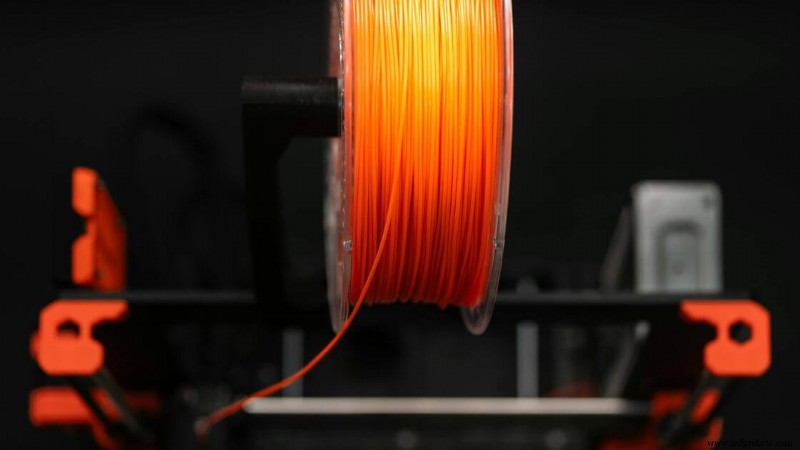
Het aanbod aan ondersteunde 3D-printmaterialen is breed. Standaard thermoplasten zoals PLA, ABS en PETG zijn gebruikelijk, terwijl geavanceerdere opstellingen koolstofvezelcomposieten, temperatuurbestendige polymeren of met metaal gevulde filamenten kunnen verwerken.
Sommige machines worden zelfs gebruikt in de bouw- of voedselmodellering.
De maatnauwkeurigheid ligt doorgaans rond de ±0,5 mm, hoewel dit varieert per apparatuur, materiaal en omgevingscontroles. Objecten met overhangen hebben vaak steunstructuren nodig om instorten tijdens het afdrukken te voorkomen. Nabewerking kan nodig zijn om de oppervlakteafwerking te verbeteren en steunen te verwijderen.
Materiaalextrusie blijft een toonaangevende keuze voor prototyping vanwege de kostenefficiëntie, vooral in vergelijking met complexere technologieën zoals selectief lasersinteren of stereolithografie. Het dient ook als basis voor gefuseerde depositiemodellering, een veelgebruikte implementatie van deze categorie.
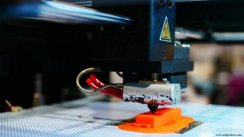
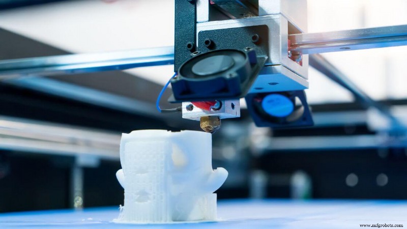
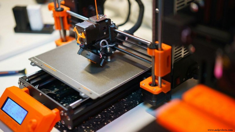
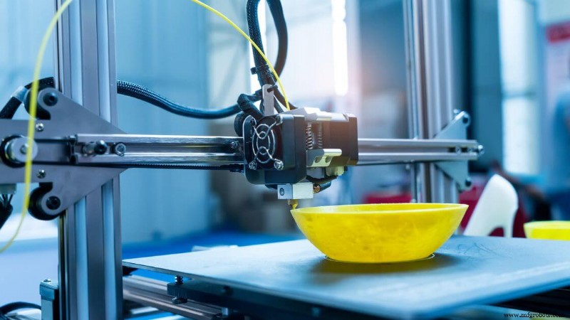
Fused Deposition Modeling (FDM) of Fused Filament Fabrication (FFF)
Fused Deposition Modeling, ook wel Fused Filament Fabrication genoemd, is een vorm van materiaalextrusie waarbij thermoplastisch filament in een verwarmde printkop wordt gevoerd. Het materiaal smelt en wordt door een mondstuk geëxtrudeerd, waardoor elke laag van het 3D-object wordt gevormd terwijl het afkoelt en stolt op de bouwplaat.
Je werkt vaak met materialen als PLA, ABS, PETG en TPU. Meer geavanceerde opties zijn onder meer polycarbonaat, ULTEM en filamenten gevuld met koolstofvezel of metaalpoeders. Deze filamenten kunnen verschillende mechanische eigenschappen bieden, afhankelijk van de functionele vereisten van uw onderdeel.
Dit proces is ideaal voor toepassingen zoals rapid prototyping, educatieve modellen, testen van consumentenproducten en productiehulpmiddelen zoals mallen of armaturen.
FDM 3D-printen is ook gebruikelijk in productontwikkelingsworkflows waarbij de geometrie van onderdelen of de pasvorm van de assemblage moet worden geëvalueerd vóór massaproductie.
Typische nauwkeurigheid varieert rond ±0,5 mm, en de laagresolutie varieert gewoonlijk van 50 tot 300 micron. De printsnelheid varieert afhankelijk van het materiaal en de complexiteit van de onderdelen, maar de standaardsnelheden liggen tussen 40 en 100 mm/s.
Pluspunten:
- Lage kosten:printers en filament op instapniveau zijn overal verkrijgbaar tegen betaalbare prijzen.
- Materiaalvariëteit:een brede selectie kunststoffen met verschillende sterktes, kleuren en afwerkingen.
- Gebruiksgemak:eenvoudige softwareworkflows maken het toegankelijk voor zowel beginners als professionals.
- Schaalbaarheid:beschikbaar van desktopmachines tot systemen op industriële schaal met grote bouwvolumes.
Nadelen:
- Zichtbare laaglijnen:Delen vertonen vaak ribbels tussen de lagen, tenzij nabewerking wordt toegepast.
- Zwakkere verbindingen tussen de lagen:mechanische eigenschappen kunnen inconsistent zijn, afhankelijk van de oriëntatie van het onderdeel.
- Ondersteuningsvereisten:voor overhangen en bruggen is mogelijk extra materiaal nodig dat later moet worden verwijderd.
- Lagere precisie:Vergeleken met 3D-printen met hars of poederbedfusie kan FDM moeite hebben met fijne details.
3D-bioprinten
 3D-bioprinten is een gespecialiseerde vorm van materiaalextrusie waarbij gebruik wordt gemaakt van bio-inkten (meestal gemaakt van levende cellen gesuspendeerd in hydrogels) om laag voor laag weefselachtige structuren te creëren.
In tegenstelling tot traditionele 3D-printmethoden die afhankelijk zijn van thermoplastische kunststoffen of metaalpoeders, geeft dit proces prioriteit aan de levensvatbaarheid van de cellen en de compatibiliteit van biomaterialen.
De extrusie moet nauwkeurig en zacht genoeg zijn om beschadiging van de levende componenten te voorkomen, terwijl tegelijkertijd functionele biologische geometrieën worden gevormd.
De materialen die je in dit proces tegenkomt, zijn onder meer biologisch afbreekbare polymeren zoals alginaat, collageen, gelatine en fibrine.
Deze dienen als steigers om de groei en rangschikking van cellen te ondersteunen. Omdat de structuren echt weefsel moeten nabootsen, worden deze materialen geselecteerd vanwege hun compatibiliteit, flexibiliteit en vermogen om vascularisatie te ondersteunen.
De toepassingen vorderen snel. Je zult zien dat 3D-bioprinten wordt gebruikt in onderzoek naar orgaan-op-een-chip-apparaten, weefselsteigers, modellen voor regeneratieve geneeskunde en zelfs biofabricage in een vroeg stadium van huid of kraakbeen. Dit zijn niet slechts conceptmodellen, het zijn praktische stappen op weg naar toekomstige implanteerbare oplossingen.
De maatnauwkeurigheid kan variëren van 100 tot 200 micron of fijner, afhankelijk van de printerkalibratie en de viscositeit van de bio-inkt. De prestaties variëren echter afhankelijk van omgevingsfactoren zoals vochtigheid, printkopcontrole en steriliteit.
De afdruksnelheid is afhankelijk van de celdichtheid, de spuitmondgrootte en de stroomsnelheid van de hydrogel. Afdrukken zijn doorgaans langzamer dan polymeerextrusie, omdat het behoud van de celgezondheid belangrijker is dan snelheid.
Pluspunten:
- Potentieel voor weefselmanipulatie:biedt een pad naar functionele organen en regeneratieve therapieën.
- Aanpasbaarheid:op maat gemaakte structuren voor het testen van geneesmiddelen of patiëntspecifieke implantaten.
- Laag-voor-laag controle:Maakt ruimtelijke plaatsing van verschillende celtypen mogelijk.
Nadelen:
- Hoge complexiteit:vereist strikte controle van temperatuur, steriliteit en consistentie van bio-inkt.
- Beperkte levensduur:Gedrukte constructies vereisen vaak onmiddellijke kweek of conditionering.
- Regelgevingshindernissen:Klinisch gebruik omvat uitgebreide test- en nalevingsstappen.
Constructie 3D-printen
3D-printen in de bouw is een grootschalige additieve productiemethode waarbij gebruik wordt gemaakt van geautomatiseerde extrusiesystemen, meestal robotarmen of op een portaal gemonteerde spuitmonden, om materialen van bouwkwaliteit, zoals beton, in gelaagde formaties af te zetten.
In tegenstelling tot traditionele methoden wordt er rechtstreeks vanuit digitale modellen gebouwd met behulp van 3D-printtechnologie, waardoor muren, structurele schillen of zelfs hele gebouwen laag voor laag kunnen worden geproduceerd zonder standaardmallen of bekistingen.
Meestal zie je materialen zoals cementmengsels, snelhardend beton, geopolymeerverbindingen en gespecialiseerde mortels die in deze systemen worden gebruikt.
De keuze van het basismateriaal moet voldoen aan strikte eisen op het gebied van vloeibaarheid en uitharding, zodat elke nieuwe deellaag goed hecht aan de vorige, terwijl de structurele integriteit behouden blijft.
Deze aanpak heeft wereldwijd aan populariteit gewonnen bij projecten die gericht zijn op duurzame, snelle en goedkope bouw. Van woningen voor lage inkomens tot noodopvangcentra en artistieke architectuur, het scala aan toepassingen groeit.
Hoewel het nog steeds in opkomst is, vind je verschillende voorbeelden uit de praktijk waarbij 3D-printers in slechts enkele dagen hele huizen of belangrijke structurele onderdelen hebben gemaakt, wat weken scheelt ten opzichte van de traditionele bouwtijdlijnen.
De nauwkeurigheid ligt doorgaans tussen ±5 mm en ±10 mm, afhankelijk van de grootte van het bouwplatform van de printer, de precisie van de spuitmondjes en omgevingsfactoren. De afdruksnelheid kan variëren, maar is vaak sneller dan handmatig werk voor rechte of repetitieve vormen. De laagresolutie is meestal grof, variërend tussen 10 mm en 30 mm, maar kan worden verbeterd met behulp van afwerkingstechnieken.
Pluspunten:
- Vermindert de arbeidsvereisten, vooral bij repetitieve taken
- Versnelt de bouwtijd dramatisch voor bepaalde geometrieën
- Minimaliseert materiaalverspilling tijdens depositiemodellering
- Maakt nieuwe, organische architecturale vormen mogelijk die niet haalbaar zijn met traditionele methoden
Nadelen:
- Vereist enorme apparatuur, waardoor de mobiliteit en het installatiegemak beperkt worden
- Materialen moeten nauwkeurig worden ontworpen voor vloeiing en snelle uitharding
- Naleving van de code en inspectienormen zijn nog steeds in ontwikkeling
- Oppervlakafwerking en onderdeelgeometrie moeten mogelijk handmatig worden verfijnd na het afdrukken
Btw-fotopolymerisatie
Vat-fotopolymerisatie is een 3D-printproces waarbij licht wordt gebruikt om lagen vloeibare hars selectief uit te harden tot vaste delen. Je begint met een vat gevuld met fotopolymeerhars, meestal op acrylbasis, dat reageert op specifieke golflengten van licht.
Een laser, digitale lichtprojector of LCD-scherm begeleidt dit uithardingsproces met hoge precisie. Terwijl elke fotopolymeerlaag uithardt, gaat het bouwplatform geleidelijk omhoog of omlaag, zodat de volgende laag zich kan vormen. Deze reeks herhaalt zich totdat het hele object voltooid is.
Wat deze methode onderscheidt, is het vermogen om extreem fijne details en ultragladde oppervlakteafwerkingen te produceren. Daarom heeft het de voorkeur voor toepassingen waarbij precisie van belang is, zoals tandheelkundige mallen, ingewikkelde sieraden en geminiaturiseerde medische componenten.
De maatnauwkeurigheid kan binnen ±0,1 mm liggen of zelfs beter op nauwkeurig afgestelde machines, en de geometrie van de onderdelen blijft consistent dankzij de gecontroleerde blootstelling aan licht en het vloeigedrag van de hars.
Je vindt dit proces ook in meerdere formaten (SLA, DLP en LCD), waarbij elk een iets andere lichtbron gebruikt, maar volgens hetzelfde algemene principe werkt:fotopolymerisatie.
Harsen die in deze machines worden gebruikt, zijn er in vele formuleringen:sommige zijn geoptimaliseerd voor taaiheid, andere voor flexibiliteit, helderheid of temperatuurbestendigheid. Sommige zijn biocompatibel, waardoor gebruik in medische prototypes of chirurgische handleidingen mogelijk is.
Houd er echter rekening mee dat ondersteunende structuren nodig zijn voor bepaalde overhangen of brugelementen, en dat deze na het afdrukken handmatig moeten worden verwijderd. Naharding onder UV-licht is meestal essentieel voor het verbeteren van de mechanische eigenschappen en het garanderen van een schoon oppervlak dat vrij is van eventuele resterende kleverigheid.
Stereolithografie (SLA)
 Stereolithografie, of SLA, was het eerste commercieel succesvolle 3D-printproces en is nog steeds een van de meest nauwkeurige. In SLA-systemen traceert en stolt een UV-laser één laag van een lichtgevoelige hars tegelijk.
Het bouwplatform verschuift vervolgens stapsgewijs, waardoor elke volgende onderdeellaag bovenop de vorige kan uitharden. Hierdoor ontstaat een naadloze structuur met uitzonderlijke oppervlaktekwaliteit.
Wat SLA uniek maakt, is het assortiment gespecialiseerde harsen. Je vindt standaardharsen voor prototypes, versies voor hoge temperaturen voor hittebestendigheid, flexibele opties voor elastische onderdelen en zelfs gietbare formules die worden gebruikt in sieraden en investeringsgietwerk. Sommige biocompatibele harsen worden gebruikt in tandheelkundige toepassingen en medische apparatuur.
Typische SLA-printers bereiken laagresoluties tot wel 25 micron en maattoleranties van bijna ±0,1 mm, afhankelijk van de onderdeelgeometrie en printinstellingen. Hoewel de printsnelheid niet het sterkste voordeel is, zijn de resultaten consistent van hoge kwaliteit en fijne details, ideaal voor conceptmodellen of kleine productieruns van precisiecomponenten.
Pluspunten:
- Zorgt voor een extreem gladde oppervlakteafwerking en minimaal zichtbare laaglijnen
- Hoge nauwkeurigheid en resolutie voor ingewikkelde functies
- De grote verscheidenheid aan harsen ondersteunt functionele en esthetische toepassingen
- Ideaal voor snelle prototyping en productieonderdelen in kleine oplagen
Nadelen:
- Hars kan broos zijn, waardoor de mechanische eigenschappen onder belasting beperkt worden
- Blootstelling aan UV-licht kan na verloop van tijd onderdelen aantasten
- Vereist nabewerkingsstappen zoals wassen en UV-uitharden
- Harskosten en printeronderhoud kunnen relatief hoog zijn
Digitale lichtverwerking (DLP)
Digital Light Processing, of DLP, is een fotopolymerisatietechniek in vaten waarbij een digitale projector wordt gebruikt om hele lagen vloeibare hars in één keer uit te harden. In tegenstelling tot stereolithografie (SLA), waarbij elke doorsnede wordt gevolgd met een UV-laser, flitst DLP een volledig beeld van de laag met behulp van een lichtprojector.
Dit proces versnelt het printen aanzienlijk, vooral bij het bouwen van meerdere onderdelen of onderdelen met een groter dwarsdoorsnedeoppervlak.
DLP is afhankelijk van fotopolymeerhars, vergelijkbaar met wat wordt gebruikt in SLA-printers. Deze materialen vereisen ondersteunende structuren voor bepaalde geometrieën en hebben vaak nabewerkingsstappen nodig, zoals spoelen in isopropylalcohol en UV-uitharding. Elke pixel in de projector wordt een voxel (in wezen een 3D-pixel), wat leidt tot zeer gedetailleerde oppervlaktekenmerken.
Deze methode is vooral handig als je fijne details en snelheid nodig hebt. Hoewel de resolutie de SLA kan evenaren of zelfs overtreffen, hangt dit sterk af van de resolutie van de projector.
Lagere systemen kunnen pixelartefacten vertonen, maar moderne desktop DLP-printers hebben dit grotendeels verzacht met verbeterde optica en kleinere pixelgroottes.
Pluspunten:
- Hart elke harslaag tegelijkertijd uit, waardoor de printsnelheid toeneemt
- Uitstekende detailresolutie, ideaal voor ingewikkelde 3D-geprinte onderdelen
- Vaak goedkoper dan SLA-systemen van groot formaat
- Consistente laaghechting en gladde oppervlakteafwerkingen
Nadelen:
- Potentieel voor zichtbare pixelvorming, afhankelijk van de projectorresolutie
- Vereist nauwkeurige kalibratie van het digitale lichtpad
- Harsvaten en optica vereisen zorgvuldig onderhoud
Liquid Crystal Display (LCD)
LCD-gebaseerd 3D-printen, ook wel gemaskeerde stereolithografie genoemd, maakt gebruik van een LCD-paneel om selectief het licht van een UV-achtergrondverlichting te blokkeren en de hars te laten uitharden. Het paneel fungeert als een sjabloon, waarbij alleen de delen van elke laag zichtbaar worden die moeten uitharden.
Deze laag-voor-laag-uithardingsmethode is vergelijkbaar met DLP, maar maakt gebruik van een LCD-scherm in plaats van een digitale projector, waardoor de opstelling compacter en betaalbaarder wordt.
De afgelopen jaren zijn LCD 3D-printers enorm in populariteit gestegen vanwege hun lage kosten, hoge resolutie en gebruiksgemak. Je zult ze vooral aantreffen in desktopmachines voor consumenten, prosumenten en zelfs in tandheelkundige of sieradentoepassingen.
Sommige modellen zijn nu voorzien van 4K- en 8K LCD-schermen om de details te versterken en zichtbare pixelvorming te verminderen, wat de oppervlakteafwerking en resolutie verbetert.
Deze printers werken met een breed scala aan fotopolymeerharsen, net als DLP- en SLA-systemen. Ze kunnen laagresoluties bereiken tussen 35–100 micron en maatnauwkeurigheden rond ±0,1–0,2 mm, afhankelijk van het bouwvolume en de schermkwaliteit.
Pluspunten:
- Budgetvriendelijk instapmodel voor 3D-printen met hars
- Compacte desktopmachines met hoge functieresolutie
- Snelle laaguitharding door uniforme belichting
- Uitstekend voor gedetailleerde prototyping en kleine productieonderdelen
Nadelen:
- LCD-schermen gaan na verloop van tijd achteruit en moeten mogelijk worden vervangen
- Effectieve resolutie gekoppeld aan de pixeldichtheid van het scherm
- Bouwvolumes zijn over het algemeen kleiner dan die van industriële alternatieven
Continue vloeistofinterfaceproductie (CLIP) en computergestuurde axiale lithografie (CAL)
CLIP en CAL vertegenwoordigen het allernieuwste op het gebied van vatfotopolymerisatie en verleggen de grenzen van hoe snel en soepel additieve productie kan zijn. In plaats van de hars laag voor laag uit te harden met discrete pauzes, richten deze methoden zich op continu printen om zichtbare laaglijnen te elimineren en mechanische zwakheden te verminderen.
CLIP, ontwikkeld door Carbon, maakt gebruik van een uniek zuurstofdoorlatend venster om een ‘dode zone’ te creëren net boven de lichtbron. Deze dunne laag niet-uitgeharde fotopolymeerhars blijft tijdens het printen in vloeibare toestand, waardoor het 3D-object continu uit het vat naar boven kan worden getrokken.
Het resultaat is dat u een extreem gladde oppervlakteafwerking krijgt en dat er geen pauzes tussen de lagen nodig zijn. Dit proces verbetert ook de sterkte van de onderdelen en vermindert de nabewerkingsbehoeften voor productieonderdelen.
CAL, nog in de kinderschoenen, benadert de uitdaging anders. Het projecteert meerdere 2D-beelden in een ronddraaiend volume vloeibare hars.
Door de geometrie vanuit alle hoeken tegelijk te reconstrueren, maakt CAL volumetrische uitharding mogelijk. Hierdoor wordt de tijd die nodig is om een complex onderdeel te produceren radicaal verkort en kunnen binnen enkele minuten volledige 3D-geprinte onderdelen worden gegenereerd.
Pluspunten:
- Extreem hoge printsnelheden zonder laag-voor-laag onderbreking
- Gladde oppervlakteafwerkingen en verminderde mechanische laaglijnen
- Uitstekend voor functionele prototypes en componenten van productiekwaliteit
Nadelen:
- Vereist geavanceerde, dure apparatuur
- Beperkte materiaalkeuze vergeleken met traditionele 3D-printers uit hars
- CAL is nog niet algemeen beschikbaar voor commercieel gebruik
Poederbedfusie
Powder Bed Fusion (PBF) verwijst naar een categorie additieve productieprocessen waarbij lagen fijn poeder, meestal polymeren of metalen, selectief worden versmolten met behulp van een hoogenergetische bron zoals een laser- of elektronenstraal.
Terwijl elke nieuwe laag poeder over het bouwplatform wordt verspreid, smelt of sintert de warmtebron specifieke gebieden, waardoor laag voor laag stevige dwarsdoorsneden van het onderdeel worden gevormd.
Wat PBF onderscheidt is het vermogen om complexe geometrieën met uitzonderlijke mechanische eigenschappen te produceren. Omdat het ongefuseerde poeder het geprinte onderdeel omringt, ondersteunt het op natuurlijke wijze overhangen en interne structuren.
Dit elimineert de noodzaak voor veel traditionele ondersteuningsstructuren, vooral in op polymeer gebaseerde systemen zoals selectief lasersinteren.
PBF ondersteunt een breed scala aan materialen van technische kwaliteit. Veel voorkomende opties zijn nylon, polyamidecomposieten, roestvrij staal, titanium en aluminium.
Deze poeders worden gekozen vanwege hun mechanische sterkte, thermische weerstand en toepassingsspecifieke kenmerken. Of u nu snelle prototypes of functionele componenten voor eindgebruik ontwikkelt, dit proces biedt een indrukwekkende veelzijdigheid.
Een van de belangrijkste voordelen van poederbedfusie is het vermogen om bijna-spuitgietkwaliteit te bereiken voor 3D-geprinte onderdelen, vooral wat betreft mechanische eigenschappen en duurzaamheid.
Het proces vereist echter geavanceerde apparatuur, inerte gaskamers (voor metaal-PBF) en vakkundige nabewerking om overtollig poeder te verwijderen en de oppervlakteafwerking te verfijnen.
PBF-systemen bieden doorgaans bouwvolumes tussen 200 en 400 mm op elke as. Veel fabrikanten gebruiken ze voor de productie van kleine series, waarbij tientallen onderdelen in één run worden genest. Deze schaalbaarheid is een belangrijk voordeel voor kosteneffectieve additive manufacturing op productieniveau.
Selectief lasersinteren (SLS)
SLS is een van de meest prominente polymeergebaseerde poederbedfusiemethoden die worden gebruikt in de 3D-printindustrie. Het maakt gebruik van een krachtige laser om poedervormig materiaal (meestal nylon- of polyamidecomposieten) te scannen en te sinteren tot solide, functionele onderdelen.
Elke doorsnede wordt laag voor laag in een verwarmde kamer versmolten, zonder dat externe ondersteuningsstructuren nodig zijn.
SLS wordt alom gewaardeerd om zijn materiaalflexibiliteit. Je werkt vaak met PA12- of PA11-nylon, soms gemengd met koolstofvezel, glaskralen of flexibele elastomeren. Deze poeders bieden een solide balans tussen sterkte, duurzaamheid en ontwerpvrijheid, waardoor SLS ideaal is voor snelle prototyping en productie van onderdelen in kleine batches.
Veel voorkomende toepassingen zijn behuizingen, mallen, beugels, armaturen, kliksluitingen en functionele testonderdelen. De maatnauwkeurigheid is doorgaans ±0,3 mm of ±0,3% van de lengte van het onderdeel, waardoor het concurrerend is met bepaalde traditionele productiemethoden.
Laagresoluties voor SLS liggen over het algemeen tussen 100 en 150 micron. Hoewel de individuele bouwsnelheden variëren per printer- en laservermogen, verbetert de mogelijkheid om meerdere onderdelen tegelijkertijd te nesten de doorvoer aanzienlijk.
Pluspunten:
- Geen ondersteuningsconstructies nodig vanwege het omringende poederbed
- Uitstekende mechanische eigenschappen, ideaal voor functionele onderdelen en onderdelen voor eindgebruik
- Sterke weerstand tegen slijtage en hitte met bepaalde technische materialen
- Compatibel met complexe geometrieën en fijne ontwerpdetails
Nadelen:
- De oppervlakteafwerking is poederachtig en moet mogelijk worden gladgemaakt of gecoat
- Hogere apparatuurkosten en onderhoudsvereisten
- Poeder moet tussen builds worden ververst of gerecycled
Multi Jet Fusion (MJF)
Multi Jet Fusion is een geavanceerde poederbedfusiemethode die wordt gebruikt bij 3D-printen. In plaats van een laser te gebruiken om poeder zoals SLS te sinteren, spuit MJF selectief een smeltmiddel op een bed van polymeerpoeder en past vervolgens infraroodwarmte toe om de deeltjes te binden.
Dit resulteert in een snellere, meer uniforme laagfusie, waardoor MJF een zeer efficiënte oplossing is in additieve productie.
Meestal zie je nylon (PA12) gebruikt worden in MJF, waarbij nieuwere ontwikkelingen zich uitbreiden naar TPU, polypropyleen en vlamvertragende materialen. Deze polymeren van technische kwaliteit zijn ideaal voor functionele onderdelen die sterkte, precisie en consistentie in mechanische eigenschappen vereisen.
MJF wordt vaak gebruikt voor productieonderdelen, behuizingen, beugels en op maat gemaakte behuizingen in kleine oplages. Mogelijk vindt u dit vooral handig voor componenten met fijne interne kenmerken of voor tekst die na het afdrukken leesbaar moet blijven.
De maatnauwkeurigheid ligt vaak binnen ±0,2 tot 0,3 mm, waardoor deze nauwkeuriger is dan veel gefuseerde depositiemodelleringsmethoden.
De laagdikte ligt doorgaans tussen de 80 en 120 micron. Omdat elke laag gelijktijdig over de volledige dwarsdoorsnede wordt versmolten, zijn de printsnelheden aanzienlijk sneller dan lasergebaseerde processen zoals SLS.
Pluspunten:
- Uniforme mechanische eigenschappen door het hele onderdeel
- Sneller dan SLS dankzij laagfusie over het volledige oppervlak
- Geen ondersteunende structuren nodig dankzij omringend poeder
- Gladdere oppervlakteafwerking vergeleken met typische gesinterde onderdelen
Nadelen:
- Hogere materiaal- en apparatuurkosten
- Nabewerking is nog steeds vereist om resterend poeder te verwijderen en de afwerking te verbeteren
Selectief lasersmelten (SLM)
Selective Laser Melting is een op metaal gebaseerd poederbedfusieproces waarbij gebruik wordt gemaakt van een krachtige laser om metaaldeeltjes volledig te smelten tot dichte, sterke delen.
In tegenstelling tot sinteren, waarbij materiaal bij lagere temperaturen samensmelt, creëert SLM volledig gestolde lagen, die qua prestaties dichter bij traditioneel vervaardigde metalen componenten liggen.
SLM werkt met materialen als roestvrij staal, titanium, kobalt-chroom en aluminium. Deze metalen worden veel gebruikt in industrieën waar sterkte, precisie en duurzaamheid essentieel zijn, zoals de lucht- en ruimtevaart, de automobielsector, medische implantaten en industriële gereedschappen.
Typische maatnauwkeurigheid varieert tussen ±0,1 en ±0,2 mm, afhankelijk van de geometrie van het onderdeel en de scanstrategie. De laagresoluties zijn prima, tussen de 20 en 50 micron, waardoor je zeer gedetailleerde componenten met complexe interne kenmerken kunt printen.
Pluspunten:
- Produceert bijna 100% dichte metalen onderdelen
- Mechanische eigenschappen komen overeen met of overtreffen traditionele productie
- Maakt zeer complexe geometrieën mogelijk, zoals roosterstructuren of koelkanalen
- Compatibel met kritieke sectoren zoals lucht- en ruimtevaart en de medische wereld
Nadelen:
- Machines zijn duur en vereisen een omgeving met inerte gassen
- Nabewerking is arbeidsintensief (verwijdering van ondersteuning, warmtebehandeling, oppervlakteafwerking)
- Lagere printsnelheid vergeleken met op polymeer gebaseerde poederbedfusie
Direct metaallasersinteren (DMLS)
Direct Metal Laser Sintering (DMLS) is een poederbedfusieproces waarbij een krachtige laser metaalpoederdeeltjes laag voor laag sintert om complexe metalen componenten te bouwen.
Hoewel DMLS vergelijkbaar is met Selective Laser Melting (SLM), kan het werken in de buurt van het smeltpunt van het metaal in plaats van het poeder volledig te smelten, afhankelijk van de vereisten voor de legering en het materiaal.
Meestal zie je roestvrij staal, gereedschapsstaal, titaniumlegeringen en op nikkel gebaseerde superlegeringen gebruikt in DMLS. Deze materialen worden vaak geselecteerd in de sectoren lucht- en ruimtevaart, industriële gereedschappen en medische apparatuur.
Functionele prototypes en productieonderdelen in kleine series profiteren van dit proces, vooral wanneer conventionele productie kostbare subtractieve bewerkingen met zich meebrengt.
DMLS bereikt maatnauwkeurigheid in het bereik van ±0,1 tot ±0,2 mm en gebruikt fijne laaghoogtes tussen 20 en 50 micron. De printsnelheid varieert afhankelijk van de scanstrategie en het machinevermogen, maar komt doorgaans overeen met andere metaaladditieve productietechnologieën.
Pluspunten:
- Maakt de creatie van geconsolideerde, zeer sterke 3D-geprinte onderdelen mogelijk
- Ondersteunt complexe geometrieën die niet haalbaar zijn met traditionele bewerking
- Minimaliseert materiaalverspilling vergeleken met CNC of gieten
- Compatibel met veel hoogwaardige legeringen die in kritische industrieën worden gebruikt
Nadelen:
- Vereist bescherming met inert gas (argon of stikstof)
- Kan interne spanningen met zich meebrengen die een warmtebehandeling na het printen vereisen
- De uitrustings- en materiaalkosten zijn relatief hoog
Elektronenbundelsmelten (EBM)
Electron Beam Melting (EBM) is een ander metaalpoederbedfusieproces, maar in plaats van een laser gebruikt het een gefocusseerde elektronenbundel om deeltjes samen te smelten.
Wat EBM uniek maakt, is de werking ervan in een hoogvacuümkamer, waardoor de oxidatie aanzienlijk wordt verminderd en materialen met hoge temperaturen worden ondersteund.
EBM wordt vaak gebruikt in combinatie met titaniumlegeringen en kobaltchroom – metalen die veel worden toegepast in de lucht- en ruimtevaart- en biomedische industrie. Het vermogen om lichtgewicht structuren met sterke mechanische eigenschappen te printen maakt het bijzonder waardevol voor orthopedische implantaten en hoogwaardige motoronderdelen.
De maatnauwkeurigheid ligt doorgaans rond ±0,2 mm of beter, en de laagdikte ligt tussen 50 en 100 micron. Het voorverwarmen van de bouwkamer helpt de restspanning te verminderen, waardoor u onderdelen kunt produceren met minimale kromtrekking.
Pluspunten:
- Uitstekend voor materialen die gevoelig zijn voor oxidatie als gevolg van een vacuümomgeving
- Hoge bouwtemperatuur verbetert de sterkte van het onderdeel en vermindert de spanning
- Levert volledig dichte 3D-geprinte onderdelen met uniforme eigenschappen
- Geschikt voor medische implantaten en componenten van ruimtevaartkwaliteit
Nadelen:
- Vereist vacuümwerking, wat de insteltijd en complexiteit vergroot
- Beperkte materiaalopties vergeleken met 3D-printen van metaal op laserbasis
- Nabewerking is nog steeds nodig voor het verwijderen van de ondersteuning en de oppervlakteafwerking
Laserpoederbedfusie (LPBF)
 Laser Powder Bed Fusion (LPBF) is een overkoepelende term voor lasergebaseerde 3D-printtechnologieën voor metaal, zoals Selective Laser Melting (SLM) en Direct Metal Laser Sintering (DMLS).
Dit additieve productieproces maakt gebruik van een krachtige laser om lagen fijn metaalpoeder selectief te smelten of te sinteren, waardoor volledig dichte en zeer complexe 3D-geprinte onderdelen ontstaan. Elke laag materiaal wordt afgezet en versmolten in een gecontroleerde omgeving, meestal met een inerte gasstroom om oxidatie te voorkomen.
Je werkt vaak met een breed scala aan 3D-printmaterialen in LPBF, waaronder roestvrij staal, titaniumlegeringen en aluminium. Deze technische materialen zijn vooral populair in de lucht- en ruimtevaart-, medische en automobielsector vanwege hun sterkte-gewichtsverhouding en het vermogen om ingewikkelde geometrieën te vormen.
De maatnauwkeurigheid ligt doorgaans tussen ±0,1 en ±0,2 mm, wat precies genoeg is voor productieonderdelen en functionele prototypes. De laagdikte varieert doorgaans van 20 tot 60 micron, waardoor fijne oppervlaktedetails mogelijk zijn. De printsnelheid varieert afhankelijk van het laservermogen, de scanstrategie en de complexiteit van de onderdelen.
Pluspunten:
- Creëert volledig dichte onderdelen met sterke mechanische eigenschappen
- Geschikt voor hoogwaardig productontwerp en industriële componenten
- Maakt complexe geometrieën mogelijk die niet haalbaar zijn met traditionele productie
- Compatibel met een breed scala aan materialen
Nadelen:
- Dure 3D-printers en poedergrondstoffen
- Vereist nabewerking (bijvoorbeeld verwijdering van ondersteuning, verbetering van de oppervlakteafwerking)
- Beperkt bouwvolume en soms langzamer voor grootschalige onderdelen
Materiaalspuiten
Material jetting is een nauwkeurig gericht additief productieproces waarbij onderdelen worden gebouwd door kleine druppeltjes vloeibaar materiaal op een bouwplatform te deponeren. Deze druppeltjes, vaak fotopolymeren of wasachtige stoffen, worden laag voor laag gestold door UV-licht of thermische uitharding.
Het proces lijkt op 2D-inkjetprinten, maar in plaats van platte afbeeldingen te maken, worden volledig driedimensionale objecten geconstrueerd.
U zult merken dat materiaalstralen ideaal is wanneer oppervlakteafwerking en details er het meest toe doen. Het bouwmateriaal wordt via meerdere spuitmonden gedoseerd, soms naast een afzonderlijk ondersteuningsmateriaal. Die ondersteuning wordt later opgelost of verwijderd, waardoor schone, ingewikkelde geometrieën achterblijven met minimale handmatige opruiming.
Omdat elke druppel met hoge nauwkeurigheid wordt geplaatst, kunnen de resulterende onderdelen meerdere materialen of zelfs meerdere kleuren binnen dezelfde print bevatten, waardoor deze zich onderscheidt van veel andere 3D-printprocessen.
Material jetting is frequently used with UV-curable resins, elastomeric inks, and waxes. These materials allow for visual prototyping, functional testing of soft-touch components, and even mold-making.
Because it can produce smooth surface finishes and capture ultra-fine resolution, it’s especially useful for design validation, medical visualization models, or overmold simulations in product design workflows.
However, this method does come with trade-offs. Photopolymers used in material jetting generally don’t match the mechanical strength of thermoplastics used in fused deposition modeling. Material costs are also higher, and parts may be sensitive to prolonged UV exposure.
PolyJet
PolyJet is a high-resolution material jetting technology that precisely jets and cures layers of photopolymer using UV light. The process builds parts with exceptional surface finish and detail by depositing droplets layer by layer, similar to an inkjet printer working in 3D. It’s a powerful option if you need visual accuracy, multiple material properties, or color simulation in a single part.
You can choose from a wide range of materials—rigid, rubber-like, transparent, or high-temperature resins—many of which are blendable in real time during printing. This allows you to replicate overmolded parts, simulate silicone or soft-touch textures, and produce full-color prototypes for marketing or ergonomic testing.
PolyJet typically offers dimensional accuracy within ±0.1–0.2 mm and layer heights down to 16 microns.
Print speed depends on the model’s size and complexity, but the ability to jet multiple materials at once increases throughput for multi-property components. It’s most commonly used for concept models, dental or medical devices, and design verification of complex assemblies.
Pros:
- Exceptional surface finish and resolution (as low as 16 microns)
- Ability to print multiple materials and colors in one part
- Smooth gradient transitions for lifelike visual models
- Supports dissolvable or water-removable support structures
- Ideal for overmold simulations and concept validation
Nadelen:
- Parts may degrade when exposed to long-term UV light
- Lower mechanical durability compared to thermoplastics
- Material costs are relatively high
- Photopolymer parts are not ideal for load-bearing functions
NanoParticle Jetting (NPJ)
NanoParticle Jetting (NPJ) is a precision-driven 3D printing process that deposits liquid suspensions containing nanoparticles of metal or ceramic materials. These suspensions are jetted layer by layer, similar to how inkjet printers work—except instead of ink, the droplets contain densely packed particles.
After deposition, the liquid carrier evaporates or is removed, and the remaining solid material is sintered in a post-processing stage to form a high-density part.
This method enables the creation of fine-featured metal or ceramic components. Common 3D printing materials for NPJ include stainless steel, zirconia, and other engineering-grade alloys and ceramics. These parts are ideal for industries that demand miniaturization and high mechanical properties, such as medical, aerospace, and electronics.
You’ll often find NPJ used for prototypes and production parts that require tight tolerances, such as surgical tools or micro-mechanical assemblies. It’s capable of producing intricate geometries and detailed surface textures without the need for traditional support structures, thanks to the inherent self-supporting nature of each layer during the drying stage.
Dimensional accuracy generally falls within ±0.1–0.2 mm, although some shrinkage occurs during sintering. Print speed is moderate and depends on part geometry and the thickness of the printed layers. Layer resolution is usually within 20–50 microns, allowing for highly detailed builds.
Voordelen:
- Capable of producing dense metal or ceramic parts with fine details
- Minimal material waste compared to subtractive methods
- No need for complex support removal systems
- Suitable for multi-material applications using different suspensions
Nadelen:
- Requires post-processing via sintering, which adds time and cost
- Dimensional changes from shrinkage must be anticipated in design
- Material options are more limited than in polymer-based technologies
- Equipment and nanoparticle inks can be expensive
Binder Jetting
Binder jetting is a 3D printing process where a liquid binding agent is selectively deposited onto thin layers of powder, gradually building up a part layer by layer. Unlike energy-intensive methods like laser sintering or melting, this approach relies on adhesion between particles to create what’s called a “green part.”
The materials used in binder jetting are diverse—metals, ceramics, sand, and polymer powders are all common.
Once a part is fully printed, it often requires post-processing to gain final strength. This may involve sintering, infiltration with metals like bronze, or curing, depending on the base material.
Binder jetting stands out for its speed and scalability. Because it doesn’t use lasers or high heat during printing, machines can process layers more rapidly and in larger volumes. However, accuracy and final density often depend on the specific post-processing route used.
Applications range from functional metal components to full-color architectural models made with plaster-like gypsum powder. You’ll also find it used in low- to mid-volume production of parts where traditional manufacturing would be cost-prohibitive.
Because it prints without the need for complex support structures, binder jetting is ideal for geometries that would be challenging with other 3D printing methods.
Metal Binder Jetting
Metal binder jetting is a subset of the binder jetting process that targets metallic powders. Instead of melting the metal directly, a print head deposits a binding agent onto the metal powder layer by layer.
After printing, the “green” part is sintered in a furnace to fuse the particles and achieve the required strength and density.
Typical materials include stainless steel, tool steel, and cobalt-chrome, which are all known for their mechanical properties and thermal resistance. This makes the process well-suited for end-use parts in aerospace, industrial tooling, and even consumer electronics.
Dimensional accuracy is typically in the ±0.3–0.5 mm range, though sintering shrinkage must be anticipated during the design phase. Print speed is a major advantage since it avoids point-by-point scanning. Layer resolution usually falls between 50 and 100 microns.
Pros:
- Lower machine and operational costs than laser-based metal 3D printing systems
- No need for support structures during the build phase
- Allows production of complex geometries and internal channels
- Ideal for batch production of small metal parts
Cons:
- Final part density may be lower than laser-melted components
- Sintering introduces shrinkage and potential warping
- Post-processing can add time and complexity
Sand Binder Jetting
Sand binder jetting is a form of binder jetting where layers of sand are selectively bonded using a liquid adhesive.
The process creates large-scale molds and cores that are primarily used in metal casting applications. Instead of producing the final part, this method builds complex sand forms that act as temporary structures into which molten metal is poured.
The materials typically include silica sand and specialty foundry-grade sands. These sands are chosen for their thermal stability and compatibility with different casting alloys.
You’ll find this method valuable in industries like automotive, heavy machinery, and aerospace, where intricate or large cast components are needed quickly.
Dimensional accuracy ranges from ±0.5 to ±1 mm, depending on sand grain size and geometry. Although the layer resolution is coarser than polymer-based processes, it’s more than sufficient for foundry-grade precision. One of the standout benefits is the high print speed, especially when producing large molds or multi-part assemblies.
Pros:
- Enables fast production of large, complex casting molds
- Eliminates traditional mold tooling, reducing cost and time
- Allows internal geometries not possible with conventional sand cores
- Scalable for industrial applications
Cons:
- Printed object is not the final part; casting is a required next step
- Limited to foundry sands; surface finish depends on particle size
- Fragility of green molds may require careful handling before use
Plastic Binder Jetting
 Plastic binder jetting operates by jetting a liquid adhesive onto fine layers of polymer powder. Over successive layers, a “green” object is formed. After printing, parts typically undergo post-processing steps—like curing in an oven or chemical infiltration—to reach final strength and durability.
Common materials used in this process include thermoplastic powders, resin powders, and sometimes full-color composites. These materials can produce vivid, detailed parts that are especially useful for visual prototypes, marketing samples, and moderate-strength components.
Dimensional accuracy usually falls within ±0.3 to ±0.5 mm, depending on geometry and finishing techniques.
Print speed tends to be high because the process avoids laser scanning, making it an efficient option for volume prototyping or display-grade production. Layer resolution typically ranges from 100 to 200 microns.
Pros:
- Ideal for full-color 3D printing with rich visual detail
- Fast throughput with relatively low machine complexity
- No laser or complex energy source required
- Good for marketing models and concept design validation
Cons:
- Requires careful curing or post-infiltration to reach usable strength
- Lower mechanical properties compared to other polymer 3D printing methods
- Parts can be brittle if not properly post-processed
Directed Energy Deposition (DED)
Directed Energy Deposition (DED) is a metal 3D printing process where material is fed directly into a high-energy source—usually a laser, electron beam, or plasma arc—which creates a melt pool on the surface of a substrate.
Wire or powdered feedstock is melted upon contact, then solidifies as you build up the part layer by layer. Unlike powder bed fusion, which forms parts in a static bed, DED uses motion-controlled multi-axis systems to apply material dynamically in various directions.
One of the major strengths of DED is its ability to add material to existing components. You can use it to repair damaged parts, reinforce areas with wear, or add entirely new features to an otherwise finished component.
This makes it incredibly valuable in aerospace, oil and gas, and defense sectors where part costs are high and downtime is expensive.
DED is compatible with a variety of metals, including stainless steel, titanium, nickel-based superalloys, and even composite materials. The process supports rapid deposition rates, which is especially useful for building large parts near net shape. However, you’ll often need follow-up machining or post-processing to achieve precision tolerances or smoother surfaces.
Since shielding gas is critical during energy deposition, a stable inert atmosphere helps prevent oxidation or contamination.
Some systems also enable gradient material transitions by blending powders during deposition.
You should consider DED if you’re looking to extend the life of expensive components, experiment with multi-material designs, or produce large-scale metallic parts that can’t be made efficiently through traditional manufacturing methods.
Laser Directed Energy Deposition
Laser Directed Energy Deposition (L-DED) is a specific type of DED that uses a focused laser beam to melt metal feedstock, usually in the form of powder or wire directly onto a build surface. This method is excellent for adding new material to existing parts or fabricating large metal structures from scratch.
L-DED supports a wide range of metals including tool steels, titanium, cobalt-chrome, and nickel superalloys.
These materials are typically used in high-performance or mission-critical applications. Think turbine blade repairs, aerospace brackets, or custom medical components where both size and strength matter.
Dimensional accuracy for laser DED generally ranges from ±0.5 mm to ±1 mm. While this is coarser than what powder bed systems can achieve, it’s often sufficient when you plan to machine the part post-build.
The layer resolution typically falls between 300 and 1000 microns, depending on the laser settings, nozzle diameter, and material feed rate.
Pros:
- Supports large parts and hybrid manufacturing with fewer size constraints
- Ideal for repair and refurbishment of high-value components
- Flexible deposition with multi-axis robotic systems
- Utilizes common welding powders, reducing raw material costs
Cons:
- Requires precision machining afterward to achieve tight tolerances
- Equipment and operation complexity drive up initial cost
- Surface finish is rougher and may require secondary processing
Electron Beam Directed Energy Deposition
Electron Beam Directed Energy Deposition (EB-DED) is a metal additive manufacturing method that uses a focused electron beam to melt metal wire or powder feedstock, layer by layer.
The process is performed inside a vacuum chamber to prevent oxidation and ensure high purity in the final part. Unlike laser-based systems, the electron beam offers deeper penetration and faster energy transfer, making it well-suited for reactive materials.
EB-DED is commonly used with titanium alloys, nickel-based superalloys, and stainless steels. These materials are ideal for aerospace, energy, and defense sectors—especially when large structural parts or critical repairs are needed.
The vacuum setup not only protects the metal from oxidation but also enhances bonding and thermal stability.
Dimensional accuracy is usually around ±1 mm, depending on the feedstock form, beam stability, and system calibration. Layer resolution is coarse, often ranging from several hundred microns to a few millimeters.
While this limits fine detail, the process shines when you need fast deposition over large areas.
Pros:
- Enables high deposition rates for large or heavy-duty parts
- Vacuum chamber prevents oxidation and preserves material properties
- Excellent for working with reactive metals like titanium
Cons:
- Requires a large vacuum system, increasing setup time and machine size
- Limited to materials that perform well under vacuum conditions
- Surface finish is rough and needs post-processing for precision
Wire Directed Energy Deposition
Wire Directed Energy Deposition (Wire DED) is a form of metal 3D printing where a spool of metal wire is continuously fed into a melt pool generated by a laser, electron beam, or plasma arc.
This process enables you to build up layers of metal quickly and efficiently, particularly when you’re dealing with large-scale structures or repairs.
Wire DED supports a wide range of materials, including stainless steel, titanium alloys, and aluminum alloys. It’s often chosen for aerospace frames, marine parts, and large industrial structures that benefit from thick wall sections and robust material properties.
Because wire feedstock is easier to handle and generally safer than metal powder, it’s also attractive for operations focused on safety and simplicity.
Dimensional accuracy for wire DED typically ranges around ±1 mm. The print speed can be quite high thanks to the continuous feed, although layer resolution is on the coarser side, often over 1 mm per layer.
Despite this, you can achieve excellent mechanical strength, especially when paired with subtractive finishing processes like CNC machining.
Pros:
- Lower material cost and safer handling than powder-based systems
- Faster build rates for large-scale parts
- Suitable for repairs and bulk material additions
Cons:
- Requires machining to achieve fine tolerances and surface finish
- Not ideal for highly detailed or intricate geometries
- Limited design freedom compared to powder-based 3D printing
Cold Spray
Cold spray is a form of directed energy deposition where metal powders are accelerated to supersonic speeds using compressed gas and then directed at a target surface.
Unlike other 3D printing methods that rely on melting, cold spray achieves bonding through solid-state deformation. When the particles hit the surface at high velocity, they plastically deform and adhere without undergoing any melting.
This unique approach enables you to apply material without the thermal stress typically associated with metal additive manufacturing.
This process is well-suited for materials like aluminum, copper, titanium, and other ductile alloys. Because of its low-heat nature, cold spray is often used in the additive manufacturing industry to repair aerospace components, restore damaged surfaces, or apply corrosion-resistant coatings.
It’s also useful for creating functional metal parts with decent mechanical properties, especially when thermal distortion must be avoided.
Dimensional accuracy tends to be relatively coarse, around ±1 mm or more due to the spray nature of deposition. Layer resolution is also limited, so you’ll often need post-processing or machining to achieve precision. However, cold spray offers fast coverage, especially for larger parts.
Pros:
- Minimal heat input reduces oxidation, warping, or thermal distortion
- Ideal for repair applications or surface coating in high-performance industries
- No melting means metallurgical integrity of base material is preserved
Cons:
- Coarse resolution and surface roughness limit use in high-detail applications
- Requires specialized, high-pressure gas equipment
- Not ideal for complex 3D printed parts or internal geometries
Molten Directed Energy Deposition
Molten Directed Energy Deposition (DED) refers to additive manufacturing processes where the feedstock—typically metal wire—is fully melted during deposition.
Unlike standard wire DED, molten DED focuses on controlling the melt pool with greater precision or alternative energy inputs, such as variable arc control or plasma transfer. This allows for more consistent material flow and fusion, especially in large-scale metal parts.
Materials commonly used include stainless steels, titanium alloys, and nickel-based superalloys. These are often chosen for applications in shipbuilding, energy infrastructure, and heavy machinery.
Whether you’re fabricating structural frames or adding material to worn parts, molten DED enables you to build big—fast.
Dimensional accuracy is usually coarse, in the range of ±1–2 mm. Layer resolution is also larger, often exceeding 1 mm per pass. But that’s a tradeoff many are willing to make for the speed and size advantages this process delivers.
Pros:
- High deposition rates make it ideal for large, bulky components
- Suitable for multi-material builds and custom alloy mixing
- Effective for adding features or repairing large industrial equipment
Cons:
- Significant thermal gradients can introduce residual stress
- Requires post-machining for accuracy and smoother surface finish
- Geometry complexity is limited compared to powder-based 3D printing
Sheet Lamination
Sheet lamination is a group of 3D printing processes where objects are created by stacking and bonding sheets of material layer by layer.
These sheets, commonly paper, metal foil, or plastic film—are either pre-coated with adhesive or fused during the build process through heat, pressure, or ultrasonic welding.
Once a layer is bonded, a laser or blade cuts the profile of the part, either before or after the bonding stage.
Unlike some additive manufacturing methods that require high-energy sources like lasers or UV light, sheet lamination operates at lower temperatures.
This makes it a more cost-effective option for producing large parts, especially in applications where surface finish or material strength is not the primary concern.
Materials often used in this process include standard office paper for color prototypes, polymer films for lightweight models, or thin metal foils for structural or embedded-function parts. Depending on the bonding and cutting technique used, the level of detail and final mechanical properties can vary.
Sheet lamination is often chosen for its speed, affordability, and ability to create large visual prototypes quickly. Its applications range from architectural models and packaging mockups to experimental builds involving embedded electronics or multi-material stacking.
Laminated Object Manufacturing (LOM)
Laminated Object Manufacturing, or LOM, is a specific type of sheet lamination where layers of adhesive-backed material are bonded together and cut to shape, one layer at a time. It works by feeding sheets—usually paper—over a build platform.
Each layer is bonded using heat and pressure, then shaped with a laser or mechanical blade based on the CAD design.
This process is straightforward and cost-effective, particularly useful when you need a large physical prototype quickly but don’t need engineering-grade mechanical properties. It doesn’t use photopolymers or require a controlled atmosphere, which makes it relatively easy to implement in an office or design studio environment.
Typical materials include standard paper, plastic films, or thin composite sheets. Paper-based builds can even include color by printing graphics onto each sheet before layering. Once the part is finished, excess material is trimmed, and post-processing like sanding or sealing can improve appearance.
The layer resolution of LOM is usually determined by sheet thickness; usually around 0.1–0.2 mm. Depending on blade sharpness and calibration, the dimensional accuracy is within ±0.5–1 mm.
Pros
- Low-cost raw materials (especially paper)
- High-speed production for large models
- Easy to operate without hazardous materials
- Simple post-processing and cleanup
Cons
- Limited mechanical properties for structural parts
- Visible layer lines, especially on paper builds
- Not suitable for fine detail or functional testing
- Significant waste from trimmed sheet margins
Ultrasonic Consolidation (UC)
Ultrasonic Consolidation is a solid-state additive manufacturing method where thin layers of metal foil are bonded using high-frequency ultrasonic vibrations. Unlike traditional 3D printing methods that rely on high heat or melting, UC fuses metal at a molecular level by vibrating the foil while applying pressure. This allows bonding without reaching the material’s melting point.
The process is part of the broader sheet lamination category in additive manufacturing. Each foil sheet is cut to shape using a CNC-controlled system and ultrasonically welded layer by layer.
Because there’s no full melting involved, this method avoids issues like residual stress or large heat-affected zones—making it ideal when you want to preserve original material properties.
Materials include lightweight metals like aluminum, titanium, and copper alloys—especially in foil form. UC can also embed sensors, wires, or electronics between layers, enabling functional integration in a single part.
Applications are most common in aerospace and defense, where you might need lightweight structures with embedded components, or multi-metal parts for complex mechanical behavior. Its dimensional accuracy typically falls within ±0.2–0.3 mm, though final machining is often performed for tight tolerances.
Print speed is moderate; each weld is fast, but layering takes time due to foil preparation and trimming. Also, the layer resolution depends on foil thickness—usually between 50 to 200 microns.
Pros
- Minimal thermal distortion and residual stress
- Can bond dissimilar metals effectively
- Supports embedding of sensors or electronics during printing
- Avoids oxidation due to solid-state bonding
Cons
- Requires specialized ultrasonic welding equipment
- Limited to foil-based feedstock
- Post-processing often required for surface finish
- Slower overall speed for large parts compared to powder-based deposition
Additive Friction-Stir Deposition
 Additive Friction-Stir Deposition (AFSD) is a solid-state 3D printing process that builds parts without melting the feedstock. Instead of lasers or electron beams, this method uses a rotating tool or nozzle to force metal in solid or near-solid form onto a base surface.
Friction between the tool and material generates enough heat to plastically deform and bond the layers. This energy-efficient process allows you to create or repair metal components while avoiding the residual stresses and porosity often seen in melt-based additive manufacturing methods.
You’ll typically see materials like aluminum, copper, and titanium used in AFSD due to their favorable mechanical properties and thermal conductivity. Since the feedstock stays below its melting point, the final part often retains better structural integrity.
AFSD is ideal for applications requiring large-scale structural builds, localized repair jobs, or multi-metal gradient structures.
It allows the integration of dissimilar alloys without forming brittle intermetallic layers—something difficult with traditional powder bed fusion or fused deposition modeling.
While the dimensional accuracy may still require post-machining for tight tolerances, the process enables unique possibilities for producing high-performance 3D printed parts with minimal distortion.
Other Emerging or Specialized 3D Printing Methods
Beyond the well-known additive manufacturing processes like fused deposition modeling and stereolithography, several specialized or still-developing 3D printing methods are gaining attention.
These techniques often tackle very specific design challenges, whether it’s printing micro-scale features, combining materials in a single build, or achieving full-color surface finishes for display models.
You’ll find these methods pushing boundaries in fields such as biomedical device manufacturing, embedded electronics, and aerospace prototyping.
Hybrid techniques are also emerging, where two or more energy deposition methods (like friction and powder) are combined.
These innovations continue to broaden the scope of 3D printing technology, expanding material compatibility, reducing printing time, and improving part resolution in unique ways.
3D Printing at Microscale or Nanoscale
When your project demands ultra-high precision, such as building medical micro-implants or lab-on-a-chip devices, microscale 3D printing enters the picture. These advanced systems use highly focused energy sources, including lasers or electron beams, to deposit or cure materials at resolutions measured in microns or even nanometers.
At this scale, specialized photopolymer resins and nanoparticle inks become essential. Some methods use two-photon polymerization to cure light-sensitive materials only at the precise focal point of a laser, allowing incredibly detailed structures to be built layer by layer. This results in 3D printed parts with minimal feature size and excellent dimensional accuracy.
Despite its precision, this method is slower than traditional processes and requires careful control over heat, material flow, and shrinkage. However, the benefits are significant when you’re working on microfluidics, drug delivery systems, or advanced electronics packaging.
Drop on Demand (DOD)
Drop on Demand (DOD) is a precision-oriented 3D printing method where droplets of build material are selectively deposited only where needed. Unlike continuous inkjet systems, DOD technology triggers each droplet individually, allowing you to achieve tight control over shape and detail. These droplets solidify immediately upon contact or through a curing process like UV exposure.
This process is commonly used for wax patterns in investment casting or small polymer parts that require detailed surface finish and dimensional accuracy. DOD printers often feature two nozzles, one for build material and one for support material that’s later dissolved or removed. Layer height can be as fine as tens of microns, making it ideal for smooth, intricate 3D printed parts.
Continuous Fiber Reinforcement (CFR)
CFR 3D printing combines traditional polymer extrusion with continuous fiber placement to boost mechanical strength. You feed fibers such as carbon, Kevlar, or glass through a specialized nozzle while depositing a thermoplastic matrix. The result is a high-strength composite that retains lightweight characteristics, something you’d want for functional parts in aerospace, automotive, or tooling applications.
The fiber paths can be customized within your computer-aided design software to align with stress loads, enhancing tensile performance where it’s needed most. Parts produced with this method often outperform metal in strength-to-weight ratio and can replace heavier components in structural designs.
Atomic Diffusion Additive Manufacturing (ADAM)
Atomic Diffusion Additive Manufacturing (ADAM) is a metal 3D printing technique that begins with metal rods encased in a polymer matrix. These rods are deposited layer by layer, forming a “green” part that retains the desired geometry but lacks full density. After printing, the part undergoes sintering, where heat causes the metal particles to diffuse and bond, resulting in a fully metallic component.
This process is ideal for complex metal parts that require simpler post-processing and is more cost-effective than some powder bed fusion systems. Since the base material is rod-shaped rather than powder, ADAM minimizes handling hazards and can increase deposition rates. It’s well-suited for prototyping, functional testing, and low-volume production of geometries that are difficult to achieve using traditional manufacturing methods. If you’re looking for a bridge between fused filament fabrication and direct metal laser sintering, ADAM is worth considering for its balance of safety, resolution, and performance
Powder Adhesion
Powder adhesion is a lesser-known additive manufacturing method closely related to binder jetting. Instead of using lasers or high-powered heat sources, it selectively bonds powder using chemical binders or controlled heat. This can involve applying infrared light or heat-absorbing agents to fuse specific regions of thermoplastic or composite powder. Each pass deposits a fine layer of material, which bonds where energy or binder is applied.
While the parts often need post-processing—such as sintering or infiltration—this technique offers flexibility in handling materials that respond poorly to direct melting. Maintaining a consistent powder bed is critical to ensure layer accuracy and part geometry. Powder adhesion processes are especially appealing for industries focused on prototyping and product development where powder bed fusion might be too costly or intense. As with most powder-based 3D printing methods, it emphasizes surface finish, build plate stability, and post-processing to refine mechanical properties and dimensional tolerances.
Plaster-Based 3D Printing &ColorJet Printing (CJP)
ColorJet Printing (CJP) is one of the few 3D printing processes capable of producing full-color models directly from CAD files, making it ideal when you need high-fidelity visuals for presentations, educational models, or marketing prototypes.
Each layer is formed by selectively depositing liquid binder and colored ink droplets onto a thin layer of gypsum powder. Over time, the printed part is built layer by layer with accurate coloring embedded in the structure.
After printing, parts can be strengthened and sealed using infiltration materials like epoxy resin, enhancing durability and vibrancy. The resulting 3D printed parts don’t possess high mechanical strength but excel in aesthetics and detail—particularly useful for architecture, figurines, and medical demonstrations.
ColorJet technology reflects the diverse applications of inkjet printing in additive manufacturing. Unlike other types of 3D printing that prioritize strength, CJP focuses on appearance, offering vibrant models at a lower cost and faster turnaround than polymer-based SLA or FDM 3D printing methods.
Selective Heat Sintering (SHS)
Selective Heat Sintering (SHS) is a thermoplastic-based additive manufacturing method that uses a thermal printhead to fuse powder rather than relying on high-power lasers like those used in selective laser sintering (SLS). The process is energy-efficient, operating at lower temperatures, and is well-suited for quick prototyping with polymers like nylon or polylactic acid (PLA).
In each layer, the printhead selectively applies heat to regions of the powder bed based on your 3D model.
As new layers are deposited, they fuse together and gradually build up the object. Since the heat input is lower than in laser sintering, SHS may result in parts with reduced mechanical properties and rougher surface finish, making it better suited for concept models than production parts.
If you’re exploring different types of 3D printing for prototyping without the cost and safety demands of laser-based machines, SHS offers an approachable entry point. It also supports workflows with smaller desktop machines and doesn’t require specialized build chambers.
Laser Metal Deposition (LMD)
Laser Metal Deposition (LMD) is a form of directed energy deposition that exclusively uses a laser as the energy source to melt metal feedstock—either wire or powder—as it is deposited. Unlike electron beam melting (EBM) or plasma-based systems, LMD is often integrated with CNC machines to convert them into hybrid platforms that combine additive and subtractive manufacturing in one setup.
This method is ideal for adding features to existing components or producing near-net-shape parts with minimal material waste. It enables precise control of the melt pool, which can help reduce thermal stress and improve overall surface finish compared to more generalized DED systems.
While it shares many traits with other 3D printing processes, its laser-based control and ability to repair or modify components mid-life make it particularly appealing for aerospace and industrial tooling applications.
Multi-Jet Modeling (MJM)
Multi-Jet Modeling (MJM) is a material jetting technique where multiple print heads dispense photopolymers or waxes in parallel lines across the build area. Each droplet is cured by UV light or solidified by cooling, depending on the material used.
This method stands out from typical inkjet printing by offering simultaneous deposition of support and build materials, allowing you to fabricate complex geometries with minimal post-processing.
Thanks to its fine resolution, sometimes under 20 microns, MJM is well-suited for concept models, investment casting patterns, and even dental devices. Because you can vary materials between jets, MJM can also create gradient structures or embed variable mechanical properties in a single build. While not the fastest of the 3D printing methods, its precision and surface quality give it a place in high-end product design and prototyping workflows.
Powder Bed and Inkjet Head (PBIH)
Powder Bed and Inkjet Head (PBIH) printing works by laying down thin layers of powder, often metal or ceramic, and then selectively depositing a liquid binder through an inkjet print head.
This technique is essentially a type of binder jetting, where the deposited binder holds the part together in a “green” state before final sintering or infiltration.
What makes PBIH unique is its material flexibility. It’s often used for research applications, small-batch production, or parts that require advanced ceramics or metal alloys. Because no lasers or thermal energy are used in the printing stage, there’s less warping and distortion, making it ideal for geometrically complex parts.
While mechanical properties depend on post-processing, this method is becoming a valuable tool in your 3D printing toolkit if you’re working with unconventional or fragile materials.
Photopolymer Jetting (PJ)
Photopolymer Jetting (PJ) is very similar to PolyJet 3D printing but can differ depending on the printer brand or specific system design. In this process, UV-curable photopolymers are jetted as tiny droplets onto the build plate and solidified with ultraviolet light.
The layer height can be extremely fine, often producing parts with a smooth surface finish and high dimensional accuracy.
Some PJ systems offer multiple nozzles for different material types, allowing you to create multi-color or multi-material prints within a single build. Other versions provide temperature-controlled print heads to maintain material viscosity for consistent droplet formation.
Because of its precision and quality, PJ is widely used in fields such as product design, dental modeling, and visual prototyping—where aesthetics and surface detail are more important than load-bearing performance.
How to Choose the Right 3D Printing Type for Your Needs?
 When choosing a 3D printing technology, start by identifying the base material that fits your project—thermoplastics, metal powders, ceramics, or photopolymers.
If you’re producing functional parts with high mechanical properties, selective laser sintering (SLS) or direct metal laser sintering (DMLS) may be better than basic fused deposition modeling (FDM).
For visual models or concept parts, stereolithography (SLA) or inkjet printing methods like Multi Jet Fusion (MJF) or PolyJet could deliver excellent surface finish and detail.
Geometry matters too. Are there overhangs, internal channels, or thin walls?
Processes like powder bed fusion or vat photopolymerization handle complex geometries better than material extrusion.
Budget also plays a role—binder jetting can offer lower unit costs at medium volumes, while traditional FDM 3D printers remain cost-effective for prototyping and consumer use.
Consider your accuracy and tolerance requirements. Some technologies like SLA or DMLS consistently hit sub-0.1 mm tolerances.
Others, such as large-format material extrusion or DED, may produce larger deviations but accommodate bigger build volumes.
Lastly, don’t overlook post-processing. Support removal, sanding, infiltration, and heat treatments all affect lead time and cost. If speed and minimal finishing matter most, aim for processes with clean support strategies or automated post-processing workflows.
Which 3D Printing Method Is Most Accurate?
If your top priority is accuracy, vat photopolymerization—especially SLA and DLP—is your best bet. These methods can achieve resolutions as fine as 25–50 microns, producing sharp edges, smooth surface finishes, and intricate features.
For high-precision metal parts, powder bed fusion technologies like DMLS or SLM are also excellent, often maintaining tolerances of ±0.1–0.2 mm.
However, final accuracy still depends on post-processing like machining or heat treatment to correct for shrinkage.
Material jetting methods such as PolyJet and photopolymer jetting also excel in accuracy and are ideal for smaller components that need tight dimensional control and visual detail.
In contrast, FDM 3D printing generally offers lower resolution and visible layer lines, though tuned machines can achieve decent results—especially for low-cost prototyping or fixtures where tolerances are less critical.
So, if you’re aiming for ultra-precise parts, start with SLA, DLP, or PolyJet, and consider metal powder bed fusion when strength and dimensional fidelity must combine.
What Is the Most Common 3D Printing Type?
Fused deposition modeling (FDM) is the most widely used 3D printing method across consumer, educational, and industrial segments.
This material extrusion process dominates due to its affordability, ease of use, and wide availability of plastic filaments.
Desktop FDM 3D printers are often priced under $500, making them ideal for classrooms, hobbyists, and small businesses. Many product designers and startups use them for prototyping and early-stage development.
Industrial FDM systems can handle engineering-grade thermoplastics with higher melting points, enabling production runs of durable parts. The popularity of FDM stems from its low entry barrier and the scalability it offers across multiple use cases.
Which Process Is Best for Complex Geometries?
Powder bed fusion (PBF), including selective laser sintering and selective laser melting, is the best method for printing intricate geometries.
It excels at producing parts with internal channels, fine lattice structures, and unsupported overhangs, especially when using polymer powder or metal powder as the base material.
Resin-based vat photopolymerization processes, like SLA or digital light processing, also perform exceptionally well with fine features and delicate structures. They provide high-resolution prints and are favored in industries requiring precision, such as dental modeling and medical devices.
Binder jetting offers similar freedom since the surrounding powder bed supports overhangs naturally. However, keep in mind that final properties depend on post-processing like sintering or infiltration. If you’re designing components with high complexity, these technologies offer the greatest design freedom.
Which Method Produces the Smoothest Surfaces?
SLA consistently delivers the smoothest surface finish among all 3D printing methods. It uses a UV laser to cure liquid resin layer by layer, producing minimal layer lines and high detail. This makes SLA ideal for visual prototypes, jewelry design, or dental models.
Material jetting also ranks high in surface quality. These systems jet tiny droplets of photopolymer and cure them instantly with UV light. The result is a nearly polished surface without the need for sanding or polishing.
For other methods like FDM or SLS, achieving similar finishes usually requires additional post-processing. Sanding, vapor smoothing, or coating can reduce visible layer lines, but the base print typically won’t match the native smoothness of photopolymer technologies.
What’s the Cheapest 3D Printing Method?
Fused deposition modeling (FDM) is typically the most affordable 3D printing method available. You’ll find low-cost desktop machines under $500, and basic thermoplastic filaments are inexpensive and widely accessible.
This makes FDM ideal for hobbyists, educators, and startups experimenting with prototyping or concept models.
Even in small production environments, its low material cost and minimal support requirements keep unit costs down.
For large prints or complex parts, however, FDM may not always remain the cheapest. Resin printers and binder jetting with gypsum can also offer cost-efficiency, especially when accuracy or color modeling is essential and post-processing is minimal.
Which 3D Printing Type Is Most Expensive?
Powder bed fusion (PBF) for metals, especially DMLS, SLM, and EBM is currently the most expensive form of 3D printing. These machines rely on high-powered lasers or electron beams, requiring precise energy deposition, inert gas handling, and extremely fine metal powder.
The cost goes beyond just the equipment. You’ll also have to factor in powder handling systems, post-processing tools, and highly trained technicians. Parts may need heat treatment or machining for final tolerances, adding labor and time.
These systems are often used in aerospace or medical sectors where performance justifies the investment, but for most users, the price tag is a major barrier to entry.
Which 3D Printing Process Is Fastest?
Continuous liquid interface production (CLIP), developed by Carbon, is among the fastest 3D printing processes. It builds parts continuously without stopping between layers, unlike most layer-by-layer techniques.
In other high-speed categories, multi jet fusion (MJF) and binder jetting also perform well. These methods apply entire layers of powder and binder in one pass, cutting down build time significantly for certain geometries.
Material extrusion can be fast when using pellet-fed systems and large nozzles, though you trade off fine detail. If you need production speed without sacrificing resolution, MJF and DLP (digital light processing) offer a strong balance.
Which 3D Printing Is Best for Metal Parts?
Powder bed fusion processes, specifically DMLS, SLM, and EBM are the best options for metal 3D printing. They produce fully dense, high-strength metal components that can match or exceed the performance of cast or machined parts.
These technologies are especially effective for complex geometries, tight tolerances, and critical applications in aerospace, medical, or tooling.
Proper post-processing like support removal, surface finishing, and thermal treatments ensures optimal results.
Binder jetting is an alternative for larger batches or lower-cost metal parts. While mechanical properties may be slightly lower, it offers faster throughput and lower material costs. For repairs or large features, directed energy deposition (DED) provides added flexibility.
Conclusie
Yes, we’ve covered a lot, but here’s the truth:choosing the right 3D printing method isn’t about picking the “best” one. It’s about finding the one that fits you.
Each process, from simple fused filament fabrication (FDM) to high-end metal printing like DMLS or EBM, has its own strengths, costs, and materials. And whether you’re building a quick prototype, a functional part, or something that looks like it came out of a sci-fi movie, there’s a 3D printing solution waiting for you.
Maybe you’re just starting out with a low-cost desktop printer and some PLA. Or maybe you’re working with engineering-grade materials for aerospace parts.
Either way, this technology lets you create faster, smarter, and more flexibly than traditional manufacturing ever could. Today, 3D printing isn’t just for experimenting, it’s shaping real production across industries.
Het beste deel? You don’t have to do it all alone. If you’re unsure which path to take, reach out to experts and 3D printing service provider like 3ERP who know the machines, the materials, and the methods.
Your perfect match isn’t just out there, it’s already printing.
CNC machine
- 1212 Hobby CNC-houtfrees - Premiumkwaliteit verzending naar Portland, VS
- Gebruik de juiste maat inbussleutels – CNC-werkplaatstip
- Saoedi-Arabië prijst onze zeszijdige CNC-boormachine en uitzonderlijke service
- G-code versus M-code:belangrijkste verschillen die elke CNC-koper moet weten
- Frezen Draaien
- Afsteken van componenten met G75 cyclus CNC-draaibankprogramma
- Professioneel tweeprocess steen CNC-bewerkingscentrum te koop
- Uiterst nauwkeurige CNC-gefreesde assemblages voor de transportindustrie in Melbourne
- Filet versus afschuining:de verschillen en functies begrijpen
- Essentiële draagbare componenten in een fiberlasersnijmachine
- Werkstukpunt voor het frezen van kleine, dunne metalen onderdelen