Industriële fabricage
Industrieel internet der dingen | Industriële materialen | Onderhoud en reparatie van apparatuur | Industriële programmering |
home  MfgRobots >> Industriële fabricage >  >> Industrial programming >> VHDL

Hoe u uw eerste FPGA LED-knipperlicht kunt bouwen:een stapsgewijze zelfstudie

Stap-voor-stap handleiding:uw eerste FPGA LED-knipperlicht bouwen

Deel 1:VHDL of Verilog ontwerpen

In deze zelfstudie leert u hoe u VHDL- en Verilog-code maakt die een LED aanstuurt op een door de gebruiker gedefinieerde frequentie. Kies de taal die het beste bij uw workflow past.

Wanneer u HDL schrijft, moet u verifiëren dat het ontwerp zich gedraagt zoals bedoeld. Fouten zijn onvermijdelijk, dus simulatie is onmisbaar. Deze tutorial is opgesplitst in twee kritieke fasen:

  1. HDL-ontwerp
  2. HDL-simulatie

Het overslaan van simulatie kan leiden tot kostbare foutopsporing op de hardware. Beschouw simulatie als een verplicht controlepunt.

Projectvereisten

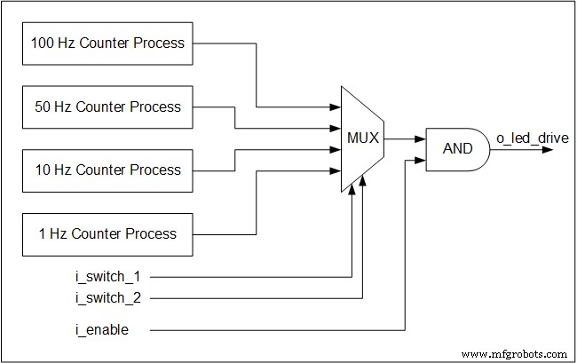
Schrijf HDL die een LED laat knipperen op 100 Hz, 50 Hz, 10 Hz of 1 Hz met een werkcyclus van 50%. Twee schakelaars selecteren de gewenste frequentie, en een extra LED_EN schakelaar moet hoog zijn om de LED in te schakelen. De FPGA werkt op een 25MHz-oscillator.

Waarheidstabel voor de frequentiekiezer:

Signaaloverzicht:

Inschakelen Schakelaar1 Schakelaar2 LED-aandrijffrequentie
0 uitgeschakeld
1 0 0 100 Hz
1 0 1 50 Hz
1 1 0 10 Hz
1 1 1 1 Hz

Vier gelijktijdige tellerprocessen bewaken de 25MHz-klok en genereren schakelaars voor elke doelfrequentie. Zelfs als een bepaalde frequentie niet is geselecteerd, blijft de teller lopen – een kernprincipe van hardwareconcurrency.

De schakelaars vormen een multiplexer die de gekozen schakelaar naar de LED-uitgang stuurt. Multiplexers zijn puur combinatorische logica en werken dus zonder klok.

Hieronder ziet u een blokdiagram dat de architectuur illustreert:

Hoe u uw eerste FPGA LED-knipperlicht kunt bouwen:een stapsgewijze zelfstudie

VHDL-implementatie

library ieee;
use ieee.std_logic_1164.all;
use ieee.numeric_std.all;
entity tutorial_led_blink is
 port (
 i_clock : in std_logic;
 i_enable : in std_logic;
 i_switch_1 : in std_logic;
 i_switch_2 : in std_logic;
 o_led_drive : out std_logic
 );
end tutorial_led_blink;
architecture rtl of tutorial_led_blink is
 -- Constants to create the frequencies needed:
 -- Formula is: (25 MHz / 100 Hz * 50% duty cycle)
 -- So for 100 Hz: 25,000,000 / 100 * 0.5 = 125,000
 constant c_CNT_100HZ : natural := 125000;
 constant c_CNT_50HZ : natural := 250000;
 constant c_CNT_10HZ : natural := 1250000;
 constant c_CNT_1HZ : natural := 12500000;
 -- These signals will be the counters:
 signal r_CNT_100HZ : natural range 0 to c_CNT_100HZ;
 signal r_CNT_50HZ : natural range 0 to c_CNT_50HZ;
 signal r_CNT_10HZ : natural range 0 to c_CNT_10HZ;
 signal r_CNT_1HZ : natural range 0 to c_CNT_1HZ;
 
 -- These signals will toggle at the frequencies needed:
 signal r_TOGGLE_100HZ : std_logic := '0';
 signal r_TOGGLE_50HZ : std_logic := '0';
 signal r_TOGGLE_10HZ : std_logic := '0';
 signal r_TOGGLE_1HZ : std_logic := '0';
 -- One bit select wire.
 signal w_LED_SELECT : std_logic;
 
begin
 -- All processes toggle a specific signal at a different frequency.
 -- They all run continuously even if the switches are
 -- not selecting their particular output.
 
 p_100_HZ : process (i_clock) is
 begin
 if rising_edge(i_clock) then
 if r_CNT_100HZ = c_CNT_100HZ-1 then -- -1, since counter starts at 0
 r_TOGGLE_100HZ <= not r_TOGGLE_100HZ;
 r_CNT_100HZ <= 0;
 else
 r_CNT_100HZ <= r_CNT_100HZ + 1;
 end if;
 end if;
 end process p_100_HZ;
 p_50_HZ : process (i_clock) is
 begin
 if rising_edge(i_clock) then
 if r_CNT_50HZ = c_CNT_50HZ-1 then -- -1, since counter starts at 0
 r_TOGGLE_50HZ <= not r_TOGGLE_50HZ;
 r_CNT_50HZ <= 0;
 else
 r_CNT_50HZ <= r_CNT_50HZ + 1;
 end if;
 end if;
 end process p_50_HZ;
 
 p_10_HZ : process (i_clock) is
 begin
 if rising_edge(i_clock) then
 if r_CNT_10HZ = c_CNT_10HZ-1 then -- -1, since counter starts at 0
 r_TOGGLE_10HZ <= not r_TOGGLE_10HZ;
 r_CNT_10HZ <= 0;
 else
 r_CNT_10HZ <= r_CNT_10HZ + 1;
 end if;
 end if;
 end process p_10_HZ;
 
 p_1_HZ : process (i_clock) is
 begin
 if rising_edge(i_clock) then
 if r_CNT_1HZ = c_CNT_1HZ-1 then -- -1, since counter starts at 0
 r_TOGGLE_1HZ <= not r_TOGGLE_1HZ;
 r_CNT_1HZ <= 0;
 else
 r_CNT_1HZ <= r_CNT_1HZ + 1;
 end if;
 end if;
 end process p_1_HZ;
 
 -- Create a multiplexor based on switch inputs
 w_LED_SELECT <= r_TOGGLE_100HZ when (i_switch_1 = '0' and i_switch_2 = '0') else
 r_TOGGLE_50HZ when (i_switch_1 = '0' and i_switch_2 = '1') else
 r_TOGGLE_10HZ when (i_switch_1 = '1' and i_switch_2 = '0') else
 r_TOGGLE_1HZ;
 
 -- Only allow o_led_drive to drive when i_enable is high (and gate).
 o_led_drive <= w_LED_SELECT and i_enable;
end rtl;

Verilog-implementatie

module tutorial_led_blink 
(
 i_clock,
 i_enable,
 i_switch_1,
 i_switch_2,
 o_led_drive
 );
 input i_clock;
 input i_enable;
 input i_switch_1;
 input i_switch_2;
 output o_led_drive;
 
 // Constants (parameters) to create the frequencies needed:
 // Input clock is 25 kHz, chosen arbitrarily.
 // Formula is: (25 kHz / 100 Hz * 50% duty cycle)
 // So for 100 Hz: 25,000 / 100 * 0.5 = 125
 parameter c_CNT_100HZ = 125;
 parameter c_CNT_50HZ = 250;
 parameter c_CNT_10HZ = 1250;
 parameter c_CNT_1HZ = 12500;
 // These signals will be the counters:
 reg [31:0] r_CNT_100HZ = 0;
 reg [31:0] r_CNT_50HZ = 0;
 reg [31:0] r_CNT_10HZ = 0;
 reg [31:0] r_CNT_1HZ = 0;
 
 // These signals will toggle at the frequencies needed:
 reg r_TOGGLE_100HZ = 1'b0;
 reg r_TOGGLE_50HZ = 1'b0;
 reg r_TOGGLE_10HZ = 1'b0;
 reg r_TOGGLE_1HZ = 1'b0;
 
 // One bit select
 reg r_LED_SELECT;
 wire w_LED_SELECT;
 

begin
 // All always blocks toggle a specific signal at a different frequency.
 // They all run continuously even if the switches are
 // not selecting their particular output.
 always @ (posedge i_clock)
 begin
 if (r_CNT_100HZ == c_CNT_100HZ-1) // -1, since counter starts at 0
 begin 
 r_TOGGLE_100HZ <= !r_TOGGLE_100HZ;
 r_CNT_100HZ <= 0;
 end
 else
 r_CNT_100HZ <= r_CNT_100HZ + 1;
 end
 
 always @ (posedge i_clock)
 begin
 if (r_CNT_50HZ == c_CNT_50HZ-1) // -1, since counter starts at 0
 begin 
 r_TOGGLE_50HZ <= !r_TOGGLE_50HZ;
 r_CNT_50HZ <= 0;
 end
 else
 r_CNT_50HZ <= r_CNT_50HZ + 1;
 end
 always @ (posedge i_clock)
 begin
 if (r_CNT_10HZ == c_CNT_10HZ-1) // -1, since counter starts at 0
 begin 
 r_TOGGLE_10HZ <= !r_TOGGLE_10HZ;
 r_CNT_10HZ <= 0;
 end
 else
 r_CNT_10HZ <= r_CNT_10HZ + 1;
 end
 
 always @ (posedge i_clock)
 begin
 if (r_CNT_1HZ == c_CNT_1HZ-1) // -1, since counter starts at 0
 begin 
 r_TOGGLE_1HZ <= !r_TOGGLE_1HZ;
 r_CNT_1HZ <= 0;
 end
 else
 r_CNT_1HZ <= r_CNT_1HZ + 1;
 end
 // Create a multiplexer based on switch inputs
 always @ (*)
 begin
 case () // Concatenation Operator 
 2'b11 : r_LED_SELECT <= r_TOGGLE_1HZ;
 2'b10 : r_LED_SELECT <= r_TOGGLE_10HZ;
 2'b01 : r_LED_SELECT <= r_TOGGLE_50HZ;
 2'b00 : r_LED_SELECT <= r_TOGGLE_100HZ;
 endcase 
 end
 assign o_led_drive = r_LED_SELECT & i_enable;
 // Alternative way to design multiplexer (same as above):
 // More compact, but harder to read, especially to those new to Verilog
 // assign w_LED_SELECT = i_switch_1 ? (i_switch_2 ? r_TOGGLE_1HZ : r_TOGGLE_10HZ) : 
 //(i_switch_2 ? r_TOGGLE_50HZ : r_TOGGLE_100HZ);
 // assign o_led_drive = w_LED_SELECT & i_enable;
 

end 

endmodule

Volgende stap:Simuleer dit ontwerp in VHDL of Verilog om het juiste gedrag te bevestigen vóór de implementatie.

VHDL

  1. Hoe maak je een Tcl-gestuurde testbench voor een VHDL-codeslotmodule?
  2. Interactieve testbank met Tcl
  3. Basis VHDL Quiz – deel 1
  4. Hoe RAM vanuit een bestand te initialiseren met TEXTIO
  5. BMP-bestand bitmapafbeelding lezen met TEXTIO
  6. Beginnersgids voor het gebruik van Modelsim voor FPGA- en ASIC-simulatie
  7. Een timer maken in VHDL
  8. Automatiseer FPGA-ontwikkeling met Jenkins, Vivado en GitHub op een Linux VPS
  9. Hoe Port Map-instantiatie te gebruiken in VHDL
  10. Hoe de tijd in VHDL te vertragen:Wacht op
  11. Voorbeeld van verklaring debouncer genereren
Signaalnaam Richting Beschrijving
i_clock Invoer 25MHz klok
i_enable Invoer Schakelaar inschakelen (logic0 =LED uit)
i_switch_1 Invoer Frequentiekeuzeschakelaar1
i_switch_2 Invoer Frequentiekeuzeschakelaar2
o_led_drive Uitvoer LED-aandrijfsignaal