Moderne jukebox
Componenten en benodigdheden
 |
| × | 1 | |||
| × | 1 | ||||
 |
| × | 1 | |||
 |
| × | 1 | |||
| × | 1 | ||||
| × | 1 | ||||
| × | 1 | ||||
| × | 1 | ||||
| × | 1 | ||||
 |
| × | 1 | |||
| × | 1 | ||||
 |
| × | 2 | |||
 |
| × | 1 | |||
| × | 2 | ||||
| × | 1 | ||||
| × | 1 | ||||
| × | 1 | ||||
| × | 1 | ||||
 |
| × | 1 | |||
| × | 4 | ||||
| × | 8 | ||||
 |
| × | 4 | |||
| × | 1 | ||||
| × | 1 | ||||
| × | 1 | ||||
| × | 1 | ||||
| × | 1 | ||||
| × | 1 | ||||
| × | 1 | ||||
 |
| × | 12 | |||
| × | 1 | ||||
| × | 1 | ||||
| × | 1 | ||||
| × | 1 | ||||
 |
| × | 7 |
Benodigde gereedschappen en machines
 |
| |||
 |
| |||
 |
| |||
|
Apps en online services
| ||||
 |
| |||
|
Over dit project
Update:zoals te zien in The MagPi Magazine, uitgave nr. 105
Inspiratie
Ik ben al jaren verliefd op klassieke jukeboxen. Al in 2014 probeerde ik er een te maken, maar ik had niet de vaardigheden voor een mooie build. Snel vooruit naar vandaag, toen ik wat vaardigheden op het gebied van 3D-printen en ontwerpen heb geleerd.
Passie, nieuwsgierigheid en verlangen dreven deze inspanning. Als je denkt dat je zo'n mini-jukebox zou willen hebben, zijn er massamarktaanbiedingen die veel zijn goedkoper, zoals dit tafelmodel Victrola voor $ 65 USD. Hackster maker flyingangel heeft een geweldige jukebox gebouwd. Aan de andere kant zijn er kant-en-klare moderne jukeboxen die groter zijn (105 cm /41,3 in H) maar veel duurder rond de $ 795 USD. Controleer de Kosten en Inspanning secties hieronder om te zien hoeveel er bij dit project betrokken is.
Toeschrijving
Dit project zou niet mogelijk zijn geweest zonder het uitstekende 3D jukebox-ontwerp van Marco Gregorio op grabcad. Het is een prachtig gedetailleerd stuk werk, des te verbazingwekkender omdat Marco geen fysieke jukebox had om van te modelleren, precies wat hij op internet kon vinden! Je bent het aan jezelf verplicht om Marco's werk te bekijken...
Ook essentieel voor de jukebox is de Arduino-code die wordt gebruikt om de LED's op muziek te laten oplichten, door Michael Bartlett op learn.sparkfun.com.
Overzicht
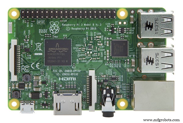
Dit is een muziekspeler die wordt aangedreven door gratis Volumio-software. Volumio beschikt over AirPlay, Spotify, Pandora, webradio en je eigen muziek, bestuurd vanaf je computer, tablet of telefoon - gewoon downloaden en installeren. Wat heb ik toegevoegd? Een 3D-behuizing, een LCD-aanraakscherm en LED's die oplichten bij muziek. Het LCD-scherm wordt gevoed door een Raspberry Pi 3 of 4. De LED's worden bestuurd door een Arduino Micro op een Adafruit Perma-Proto-bord bevestigd aan de bovenkant van een hardware-stack:Raspberry Pi en IQAudio Pi Digi Amp.
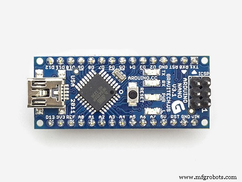
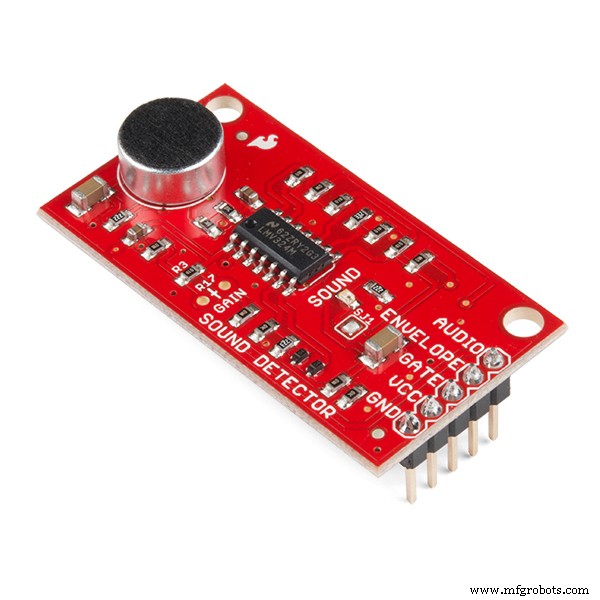
Ik gebruik oude hardware, het IQAudio-versterkerbord en een Arduino Micro, die ik in voorraad had. Op het moment van schrijven maakt IQAudio nu deel uit van Raspberry Pi, en de Pi Digi Amp Plus is nog steeds beschikbaar, EN voor minder dan wat ik ervoor heb betaald. De Arduino Micro is verouderd, maar je zou een Arduino Nano of Adafruit Itsy-Bitsy kunnen gebruiken. U moet aanpassingen maken voor analoog en digitaal pingebruik en het voeden van 5V-stroom van de Digi Amp naar het dochterbord (Arduino). Ten slotte transformeert een Sparkfun-geluidsdetector op magische wijze geluid in digitale bits.
Marco leverde een STEP-bestand voor alle componenten van de jukebox die ik kon importeren in de Fusion 360 3D-ontwerptoepassing. Wat ik deed was:
- Schaal het model op 25% van het volledige model van Marco
- Bekijk de modelcomponenten en beslis wat u wilt behouden en wat u wilt toevoegen
- Verborg de delen van het model die ik niet heb gebruikt
- Functies toevoegen en wijzigen om een handige behuizing te maken
- Druk de 3D-lichamen af die de behuizing vormen
- Voeg elektronica toe om Volumio en de LED's van stroom te voorzien
Ontwerpdoelen
- Wees ongeveer 381 mm hoog
- Touchscreen met Now Playing/Album Art
- Fatsoenlijk klinkende luidsprekers
- Lichtjes... Het moest veel mooie, geanimeerde LED's hebben
- Eigenlijk KIJK ALS het is 3D-geprint (geen nabewerking van de print); dat betekende printen in verschillende filamentkleuren
- Geen 3D-prints langer dan ongeveer 12 uur (geen nachtelijke prints)
- Verberg of minimaliseer verbindingen van onderdelen
Vaardigheidsniveau:gevorderd
- Meer dan 75 uur totale afdruktijd voor 3D-onderdelen
- Kritische montage - je moet dingen "precies goed" doen, dingen in een bepaalde volgorde doen
- Beperkte ruimte om in de koffer te werken als u klaar bent
Kosten:Duur
(Alle kosten USD)
Op een absoluut minimum:
- Als je nabewerkt, heb je 2-3 rollen wit 3D-filament en afwerkingsbenodigdheden nodig, geschat $ 70-90
OF
- Afhankelijk van wat je hebt. Ik moest gewoon een spoel rood filament kopen, ongeveer $ 30. Ik ben 3D-printen sinds 2017 en het is een belangrijk tijdverdrijf voor mij. Ik had zilver, wit, bruin en zwart filament in voorraad. Die, plus een rode spoel, zou minstens . zijn rond de $ 100.
- Arduino Nano of Adafruit Mini Metro, ongeveer $ 20 (ik had Arduino Micro in voorraad)
- Adafruit Raspberry Pi Perma Proto-hoed $5
- HDMI-aanraakscherm (Uctronics) 5 inch, $ 53
- Raspberry Pi 3B Plus $35 (bij de hand)
- Onderdelen Express Dayton Audio RS100-8 luidsprekers, 2x $60 totaal (in voorraad)
- Onderdelen Express-luidsprekerkabel, 18AWG ongeveer $ 20 (op voorraad)
- Parts Express Speaker Grille Cloth, $30 (in voorraad)
Reken op nog eens $ 40 of meer voor HDMI-kabels / connectoren, schakelaars, bevestigingsmateriaal, jumperdraden, vrouwelijke header, enz. Ik had er veel van in voorraad. Voor mij waren de huidige contante kosten ongeveer $ 150, verspreid over maanden, omdat ik zoveel benodigdheden bij de hand had. Als je al die benodigdheden zou moeten kopen... Nou, reken maar uit.
Voor mij waren de kosten het waard.
Inspanning
De 3D-prints duren 75 uur of langer, afhankelijk van uw printer. Er zijn 21 verschillende delen met ongeveer 12 die meerdere uren in beslag nemen om af te drukken. De overige delen duren elk ongeveer 1-2 uur. En dat in de veronderstelling dat je geen afdrukken hoeft te maken.
Ik heb hete lijm gebruikt om de delen van de behuizing voor te bereiden en aan elkaar te hechten, in 4 fasen. Reken op 3-4 uur. daarom. Het lijmen van de LED-strings duurt ongeveer een uur voor installatie en uitvoering. Er is ook een nauwkeurige verlijming van kleine decoratieve onderdelen (met CA-lijm) om de jukebox af te maken.
Reken voor de elektronica minimaal 5 uur om:
- Installeer Volumio
- Installeer Arduino-schets
- Leg de printplaat in en soldeer deze
- Test of alles werkt voor de eindmontage!
- Het LCD-paneel monteren
- Monteer de RPi, IQAudio Digi Amp Plus en Perma Proto-kaart in een stapel
- Solderen en monteren van de schakelaars en stroomaansluiting
- Bevestig de luidsprekers en luidsprekerkabels
Het definitieve lijmen kan 1-2 uur duren.
Samenvattend, naast de tijd om alle onderdelen af te drukken, kan de montage ongeveer 12 uur of langer duren.
Downloads
Documentatie, code en 3D-printbestanden zijn beschikbaar op github.
3D-afdrukbestanden zijn ook beschikbaar op thingiverse.
3D-printen
Er zijn in totaal 21 afzonderlijke STL-onderdelenbestanden. Voor sommige onderdelen zijn 2 exemplaren/afdrukken nodig.
Aan de slag
Zorg ervoor dat u de opmerkingen in de secties "Dingen" aandachtig leest. Ze geven de nodige informatie over de exacte componenten die moeten worden gebruikt. Als u onderdelen vervangt, moet u uitzoeken welke wijzigingen moeten worden aangebracht.
Om er zeker van te zijn dat alles werkt, test u of alle elektronica samenwerkt voordat u de behuizing in elkaar zet:
- Installeer en configureer Volumio
- Soldeer de printplaat
- Bekabel componenten:NeoPixels, slow-fade RGB LED en schakelaars
- Voeg componenten toe aan het bord
- Download de Arduino-schets van github
- Upload de schets naar de Arduino, gemonteerd op het bord
- Probeer het allemaal uit
Installeer Volumio
Ga naar de Volumio Aan de slag-pagina en volg de installatiehandleiding voor je Raspberry Pi. Om te beginnen met testen, monteer je de IQAudio Pi Digi Amp op de Raspberry Pi, steek je de versterker in de vrouwelijke header op de Pi en gebruik je afstandhouders van de Pi naar de IQAudio Amp, zoals weergegeven in de onderstaande foto. Raadpleeg later deze handleiding om ze in de 3D-geprinte jukeboxbodem te monteren.
_9H4kWWGtUT.jpeg?auto=compress%2Cformat&w=680&h=510&fit=max)
Sluit twee vrouwelijke naar mannelijke jumperdraden aan op de +5V- en GND-aansluitingen van de Digi Amp Plus, zoals weergegeven in de onderstaande foto. Deze worden aangesloten op het Perma-Proto-bord om de NeoPixels rechtstreeks van stroom te voorzien vanaf de Pi Digi Amp Plus.
Bij het nieuwste model Digi Amp zijn alle header-pinnen van de Pi zichtbaar, dus de 5V- en GND-pinnen bevinden zich op de standaard Pi-headerpinlocatie.
_4dxCv32yCp.jpeg?auto=compress%2Cformat&w=680&h=510&fit=max)
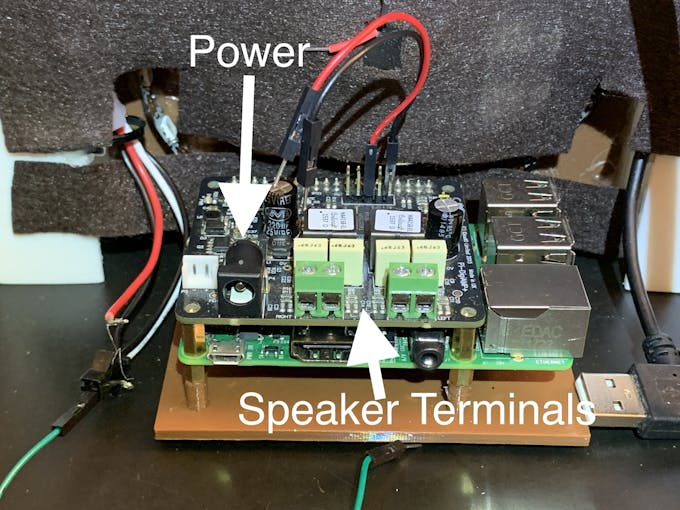
Om de luidsprekers op te stellen, knipt u twee paar luidsprekerdraden (14-26 AWG) van ongeveer 18 cm lang door en bevestigt u deze aan uw luidsprekeraansluitingen en de IQAudio-schroefaansluitingen. De Pi wordt aangedreven door de IQAudio - NIET steek de stroom in de Pi-stroomaansluiting. Sluit een stroomblok aan op de IQaudio en probeer wat webradio van volumio af te spelen.
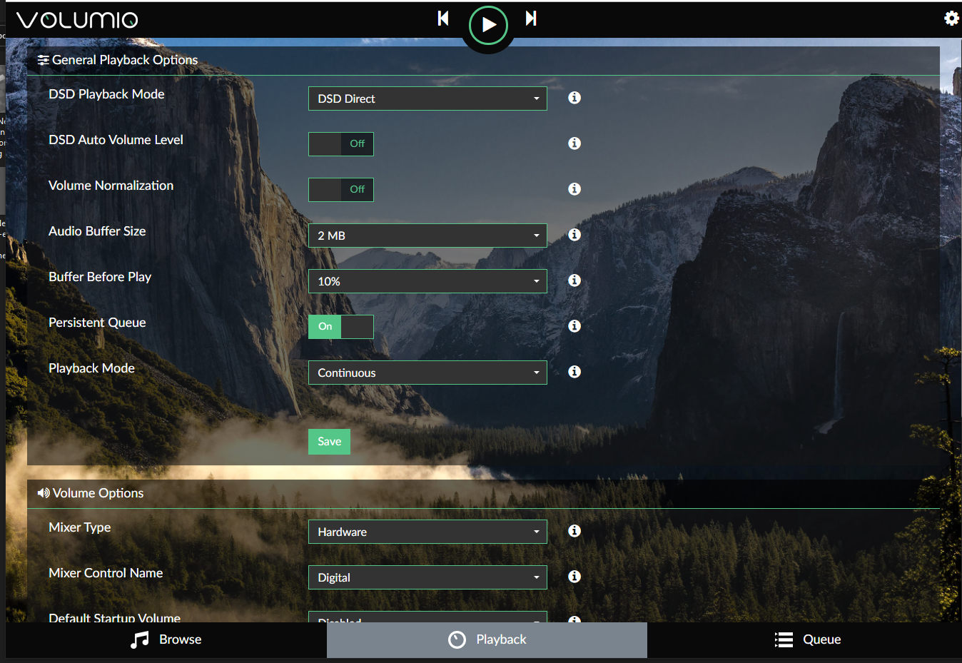
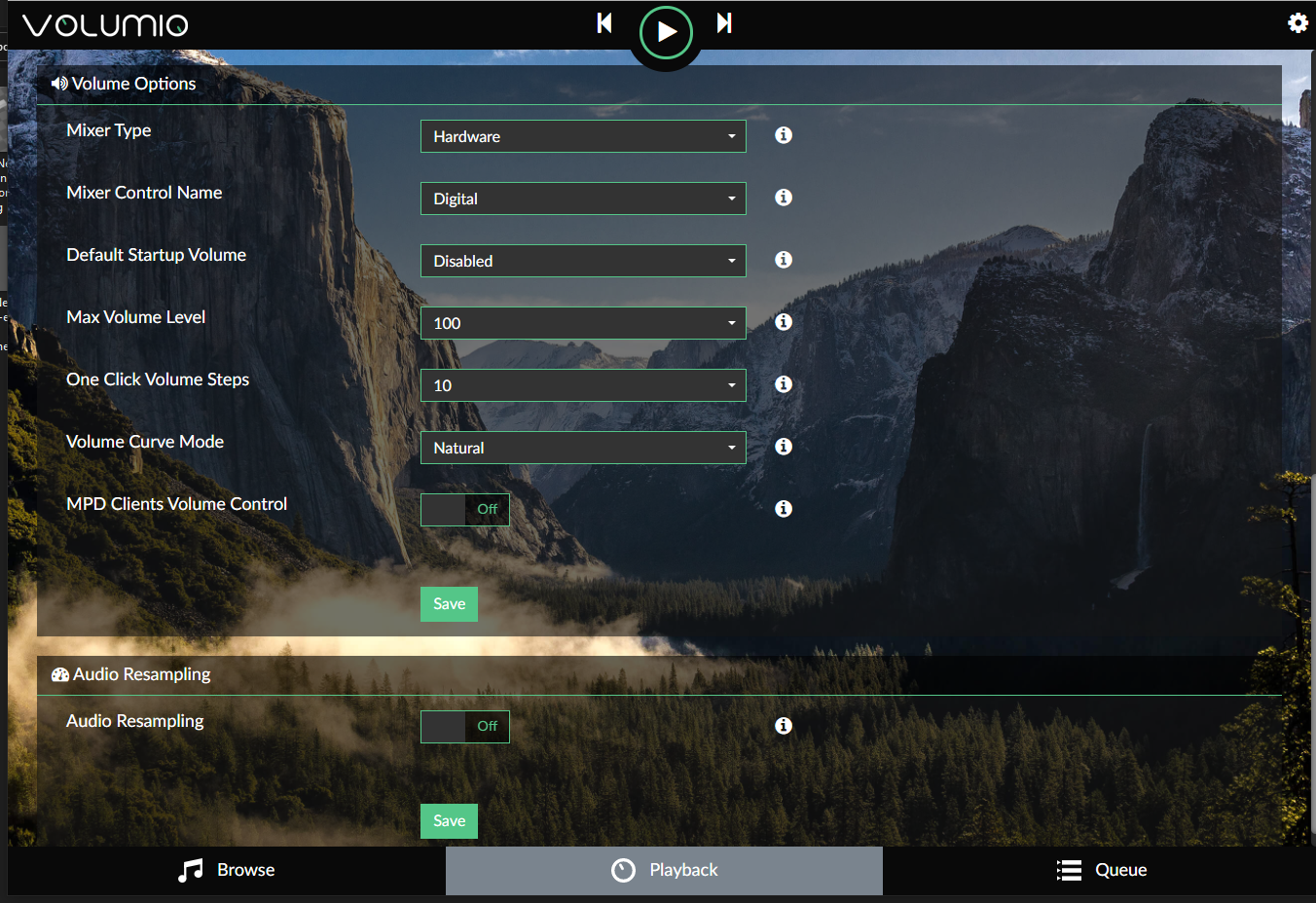
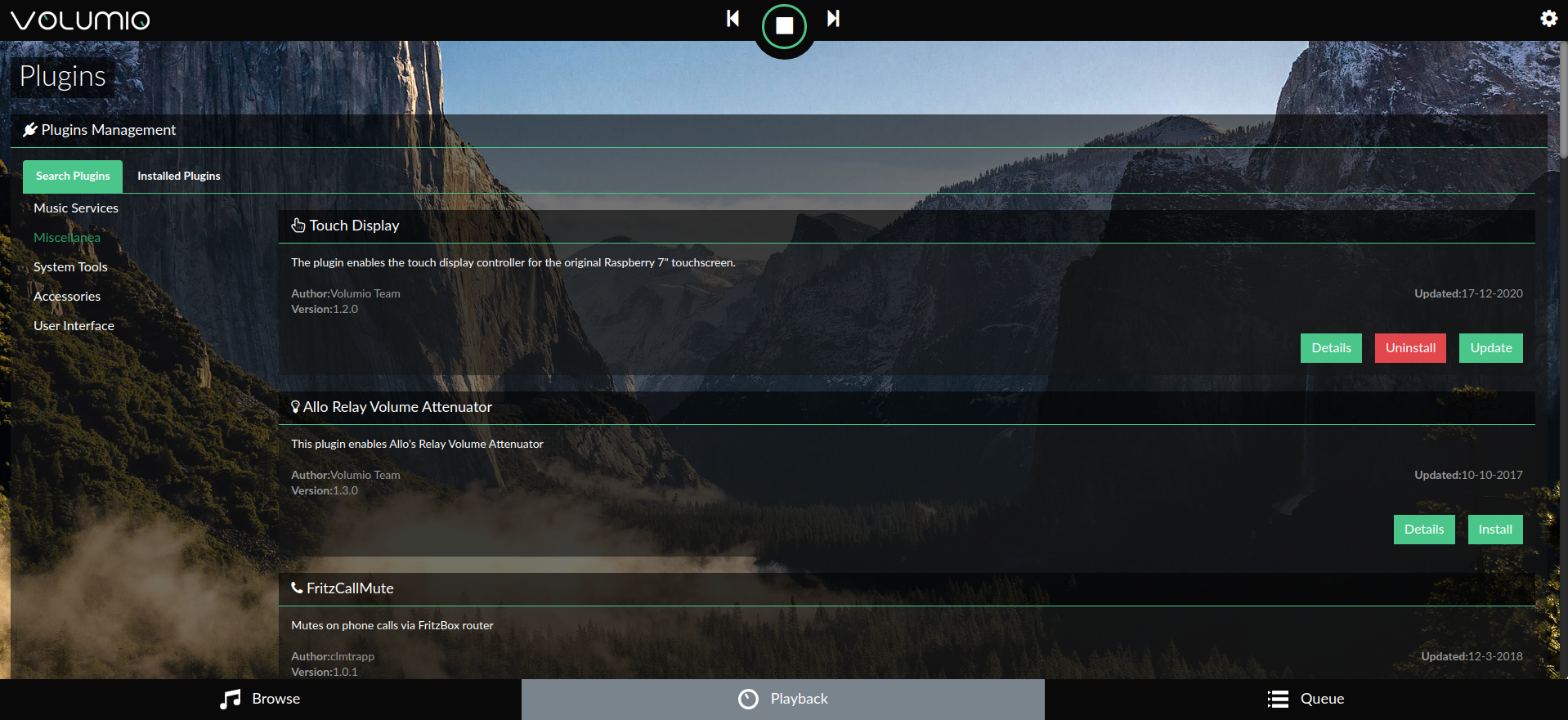
De onderstaande galerij toont de Volumio-instellingen voor de IQAudio Pi Digi Amp Plus en de Touch Screen-plug-in (Instellingen/Plugins/Miscellanea):
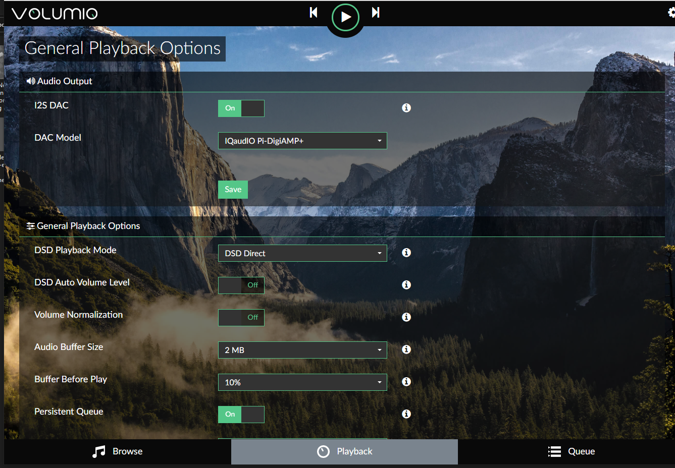
Raadpleeg de Snelstartgids en Eerste stappen met Volumio om aan de slag te gaan met Volumio.
Bereid de printplaat voor
De vormfactor van het Adafruit Perma-proto-bord paste goed op de Pi en de IQAudio-versterker, en vormde een goed draag-/dochterbord voor de Arduino.
Het bord is alleen aangesloten op de IQAudio 5V en GND voor stroom. Dus de gebruikelijke vrouwelijke header om verbinding te maken met een Pi werd niet gebruikt.
Voor optimaal gebruik van de beschikbare ruimte op het proto-bord, richt u het bord zo dat de rail met de markering "3.3V" zich bovenaan bevindt.
Ik pas het proto-bord aan op manieren die iets minder vaak voorkomen dan alleen punt-naar-punt bedrading:
- De 3,3V-rail wordt daadwerkelijk gebruikt voor 5V-invoer .
- Snijplanksporen om meerdere pinverbindingen in één kolom te plaatsen
- Spoorsporen snijden op de onderste, op het bord gemarkeerde 5V-rail, om meerdere pinnen in één rij toe te voegen
Deze dingen droegen bij aan een goed ingedeeld bord, als het gevuld was.
Raadpleeg deze fotogalerij voor bedradingsaansluitingen en aanpassingen:
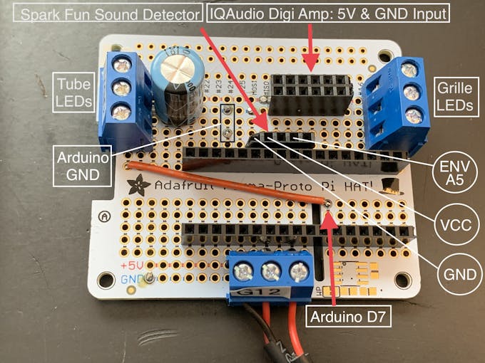
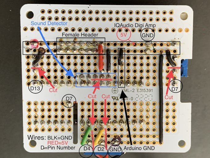
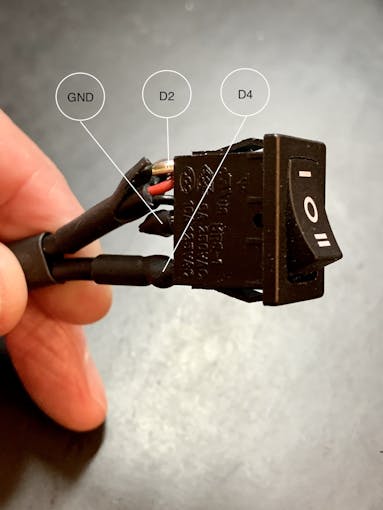
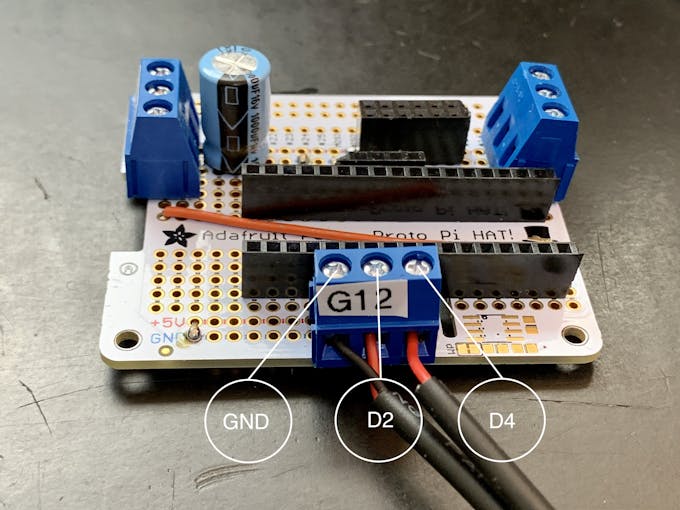
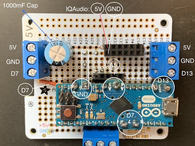
Opmerking: De 3-pins terminals hebben een pin-to-pin pitch van 5,08 mm. Dat is precies 2x de standaard 2,54 mm pitch van via's op het protobord. De schroefaansluitingen/pinnen zijn dus elk 2 bordvia's uit elkaar. De indeling van het bord en het uitsnijden van sporen is afhankelijk van die afstand. U kunt een 3-pins/2,54 mm steekklem niet vervangen zonder de kaartlay-out te wijzigen.
Animatieselectieschakelaar
U moet ook een tuimelschakelaar met drie standen aansluiten, zoals weergegeven op de foto's. Knip 3 stukken aansluitdraad van ongeveer 18 cm voor deze schakelaar, bij voorkeur twee zwarte (GND) en één rode (+V).
Hieronder meer over deze schakelaar.
Neopixels
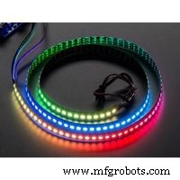
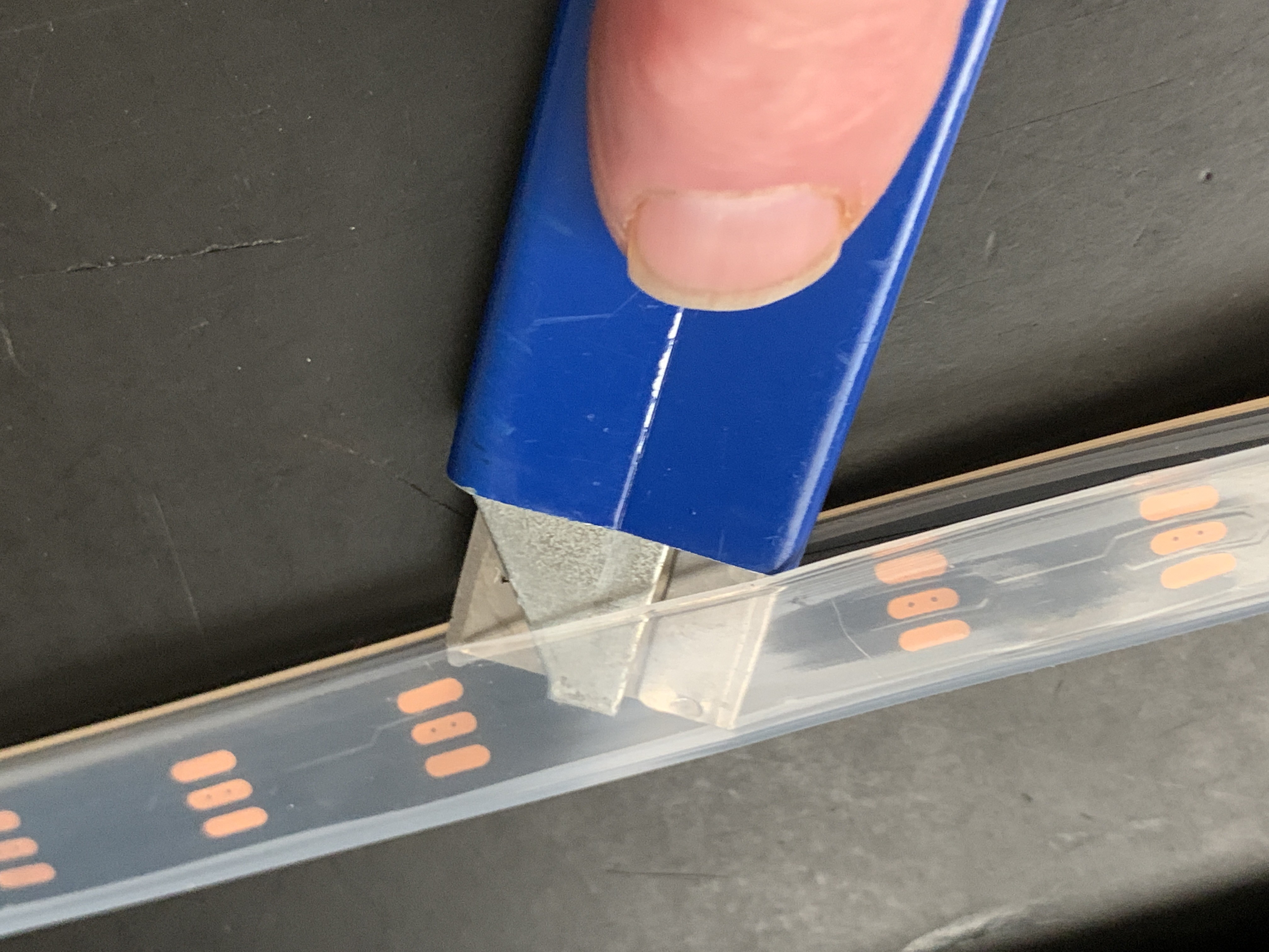
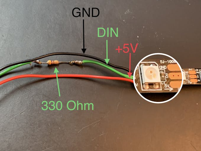
Verwijder het siliconen omhulsel van een Neopixel-koord van één meter lang. Snijd de Neopixel-strip in twee delen, een 36 LED's en een met 22 LED's. De korte strook zal de voorgrille omringen. De 36 LED-lengtestrip komt in de buitenste buizen (Neon Tubes) te zitten. Knip 3 stukken aansluitdraad van ongeveer 18 cm voor elke snaar (u kunt deze later inkorten). Sluit elke sectie aan met draden voor GND, +V en DIN, en zorg ervoor dat deze overeenkomen met de DIN-richting op de snaar. Voeg een weerstand toe in lijn met de DIN-aansluiting (330 Ohm werkt).
Sterrenlicht
In de voorgrille bevindt zich een 3D-geprint inzetstuk in de vorm van een 6-puntige ster (Star Light). Een RGB slow-fade LED die +V en GND gebruikt, wordt achter deze Star Light gemonteerd, ingevoegd in een 3D-geprint schot om doorbloeding te voorkomen. Patch in een 120 ohm weerstand in-line op de +V jumperdraad. Hierdoor daalt de stroom van 5V naar ongeveer 3,4V naar de LED. Dit wordt gebruikt in de sectie Montage-/roosterdoek hieronder.
Arduino
Als je de Arduino IDE nog niet hebt geïnstalleerd, download en installeer deze dan aan de hand van deze instructies.
Je hebt de Neopixel-bibliotheek nodig om de LED's te laten werken.
De geluidsreactieve Neopixels zijn gebaseerd op de Interactive LED Music Visualizer-schets van Michael Bartlett op Sparkfun. Ik gebruikte de "Full Visualizer" zonder knoppen, ik voegde een tuimelschakelaar toe die drie functies heeft:
- LED's reageren op muziek - schakelpositie 1
- LED's in een van kleur veranderend "chaser" -patroon, NIET geluidreactief - schakelaarpositie 2
- LED's uit - schakelpositie midden
De LED's werken niet tenzij de schakelaar is aangesloten.
Download de schets van de Jukebox LED's van github.
Verbindingen
- Monteer je Arduino op de vrouwelijke headers van het protobord
- Bevestig de 36-LED-strip aan de terminal die is aangesloten op digitale pin 7.
- Bevestig de 22-LED-strip aan de terminal die is aangesloten op digitale pin 13
- Plaats de Sparkfun-geluidsdetector.
- Bevestig de tuimelschakelaar:middelste paal op GND, positie 1 op pin D2, positie 2 op pin D4
- Sluit de IQAudio Digi Amp Plus +V en GND aan op de vrouwelijke headers voor de 5V-rail op het Perma Proto-bord (in foto's hierboven)
- Sluit de slow fade RGB aan op de +V en GND vrouwelijke headers
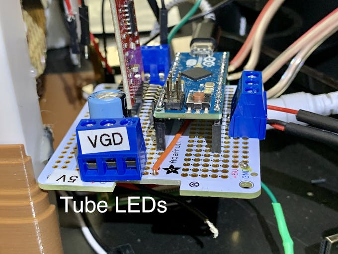
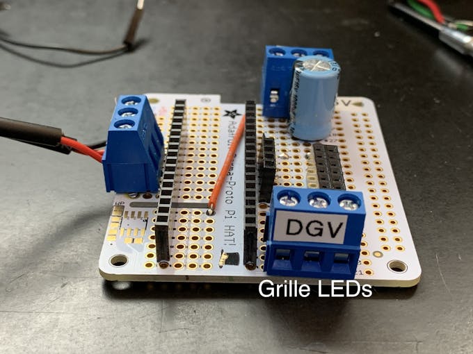
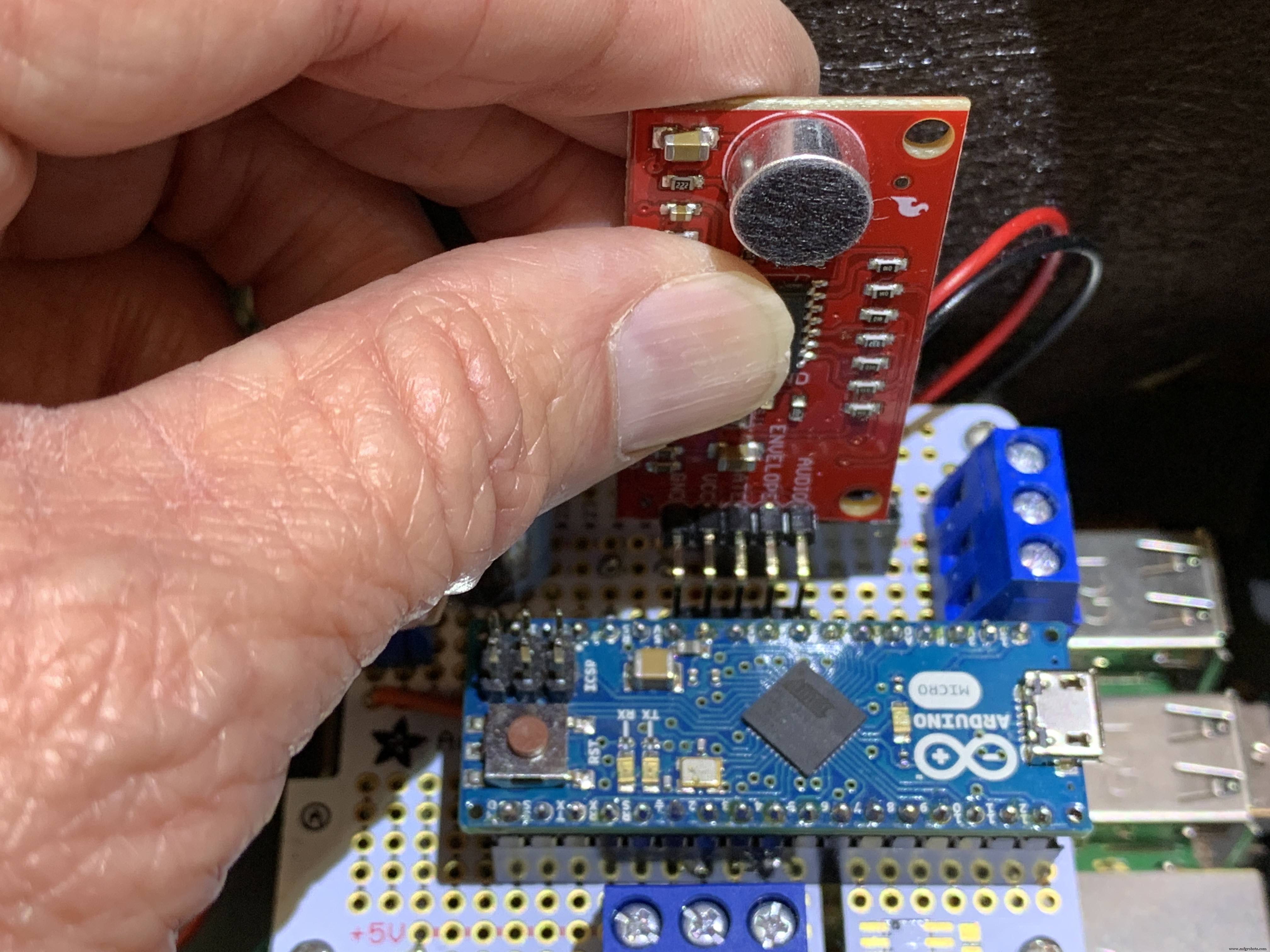
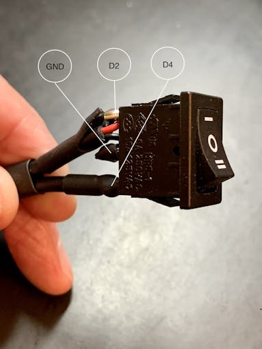
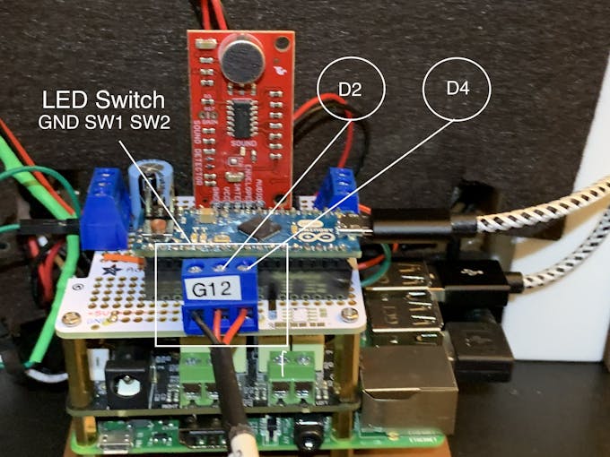
Upload de schets van de Jukebox-LED's naar uw Arduino-bord. De grille-LED's doorlopen een RainbowCycle-routine in de sketch setup-functie, wat even tijd kost. De geluidsreactieve LED's werken dus niet meteen. Nadat de setup-functie is uitgevoerd, blijven de LED's van het rooster altijd aan, onaangetast door de stand van de tuimelschakelaar. Als er muziek van Volumio wordt afgespeeld, moeten de neonbuizen op muziek reageren met de tuimelschakelaar met 3 standen op stand één. Switch position two passes a color-wheel/chaser pattern through the Neon tubes. Center position on this switch turns the Neon LEDs off.
3D-printen
Check the docs folder of the github download for part identification (Parts List) and Print Times for each part. There are also screenshots of the Prusa Slicer parameters and orientation to guide how to print each part. Find those in the 3D-Prints folder.
NOTE: All images are of the prototype jukebox I built. These will look different from the published Fusion 360 design archive and STL files. The final release STL files include improvements for the following:
- Increase the size of the bezel on the LCD touch screen
- Increase the size of the mounting plate to allow more clearance
- Remove the 3D printed standoffs on the mounting plate and just use holes with screws inserted from the bottom of the mounting plate
- Simplified the back cover
Montage
Tools
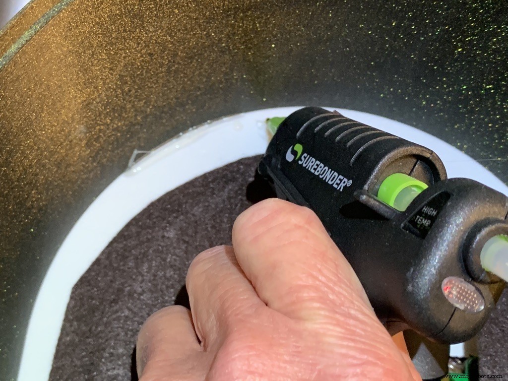
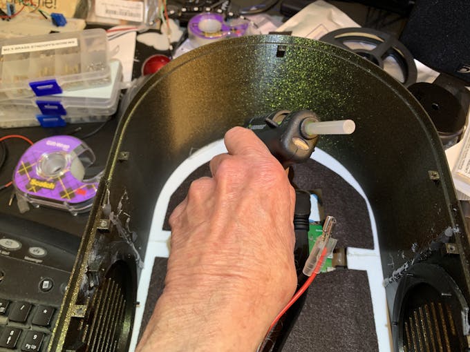
I used a fine-tipped hot glue gun so I could get into smaller spaces. These use smaller diameter glue sticks, and lots of them.
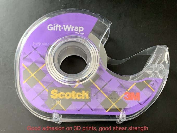
I used some tape I had on hand to temporarily hold the parts together for gluing. I found Scotch Gift-Wrap tape was actually pretty good for this. It has good adhesion and strong shear strength.
Behuizing
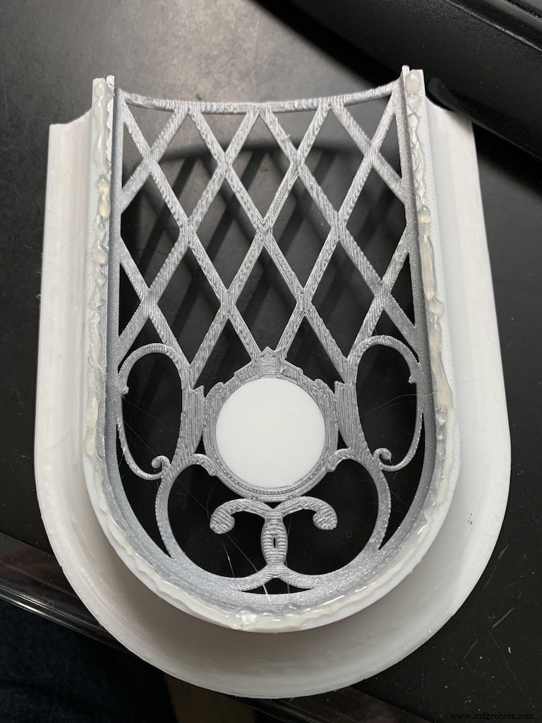
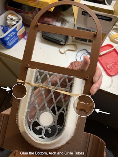
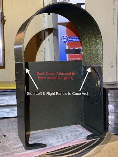
The parts are glued in starting from the inside, the Grille, and moving to the outside, the Neon Tubes, as shown in the video below.
Pause after gluing the Neon Tubes and mount the following hardware. This will give you more space to work in, before you glue in the back case. Refer to the Assembly Gallery photos below for details.
- Acrylic Window with photo
- NeoPixels
- LCD Touch Screen
- Grille Cloth and Star Light Holder
- Raspberry Pi/IQAudio Pi Digi Amp/Arduino
- Adhesive Felt (or paper) backing
- Base with switches
Then continue gluing the Case and Base to the other assembled parts.
After the case is fully assembled and glued together, mount the Speakers and add Decorations.
There is an optional two-piece 3D printed case cover that screws into the back of the case.
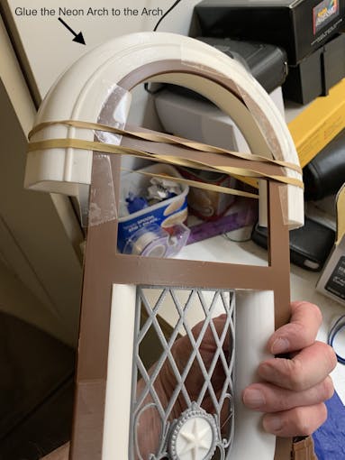
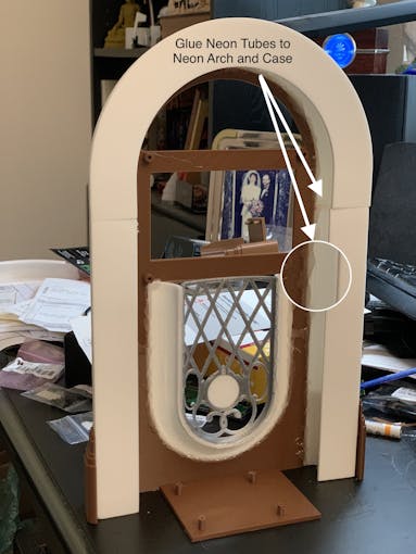
_k2oC39lKQk.jpeg?auto=compress%2Cformat&w=680&h=510&fit=max)
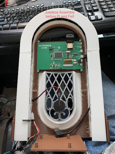
Mounting the Hardware
In the following, all the hardware mentioned is found in the "Things" section.
“Right” and “Left“ are your right and left as you face the front of the jukebox.
Acrylic Window and Photo
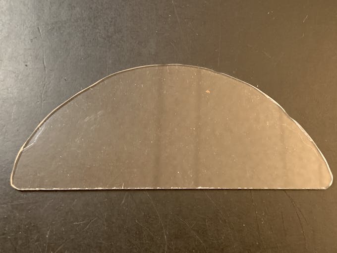
Use a rotary tool (eg., Dremel) at slow speed to cut a piece of clear acrylic. There is a template for this in the github download. Tape the template down on the acrylic and cut around the outside. Sand the edges and use CA to glue into the top of the Arch. Print a photo of your choice that will fill up the visible area and glue that in back of the acrylic.
NeoPixels
Glue the long LED strip edge-on to the Neon Tubes, so that the LEDs are facing inward to the Tubes. There is a small space between the LED and the edge of the strip that can help fit the string against the Neon Tubes. Align that to glue down.
The Grille Tube NeoPixels will be glued onto the Left and Right Bottom, with a "U" shape near the board mounting plate. Hold the strip down with pieces of tape and tack spots with hot glue. When those are solid, remove the tape and fill in the spots where the tape was with more glue.
LCD Touch Screen
Screw the Touch Screen into the mounting posts at the top of the Arch, below the Acrylic window. The HDMI Touch Screen input is on the top of the screen. You need to insert a 90 degree to 270 degree HDMI adapter there, Plug the HDMI 1 ft. Male-to-Male flat cable into the adapter. The other end plugs into a Raspberry Pi 3. (If you're using a Raspberry Pi 4, you need a different cable that has a Micro HDMI in one end). Insert the Left-angle Micro USB to the Touch port on the LCD, and the USB-A end to a Raspberry Pi port. Thread this cable through the left Neon Tube.
Grille Cloth and Star Light Holder
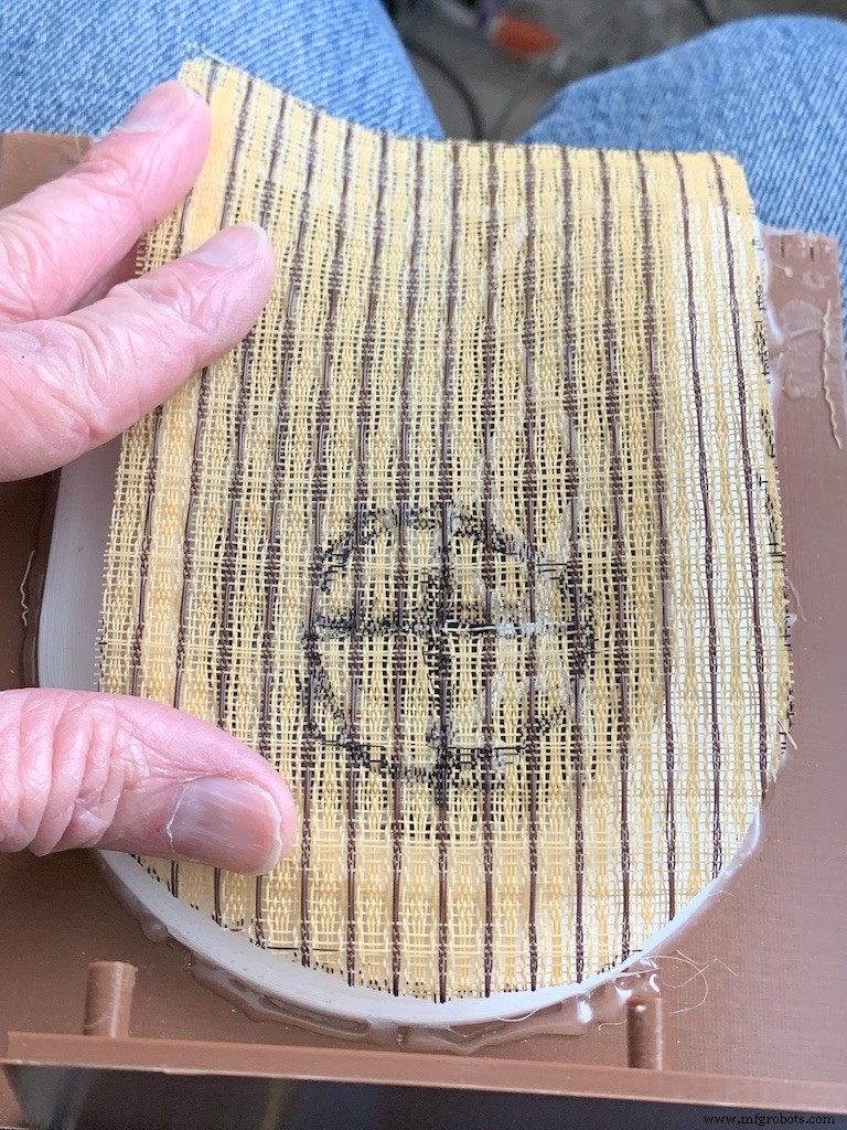
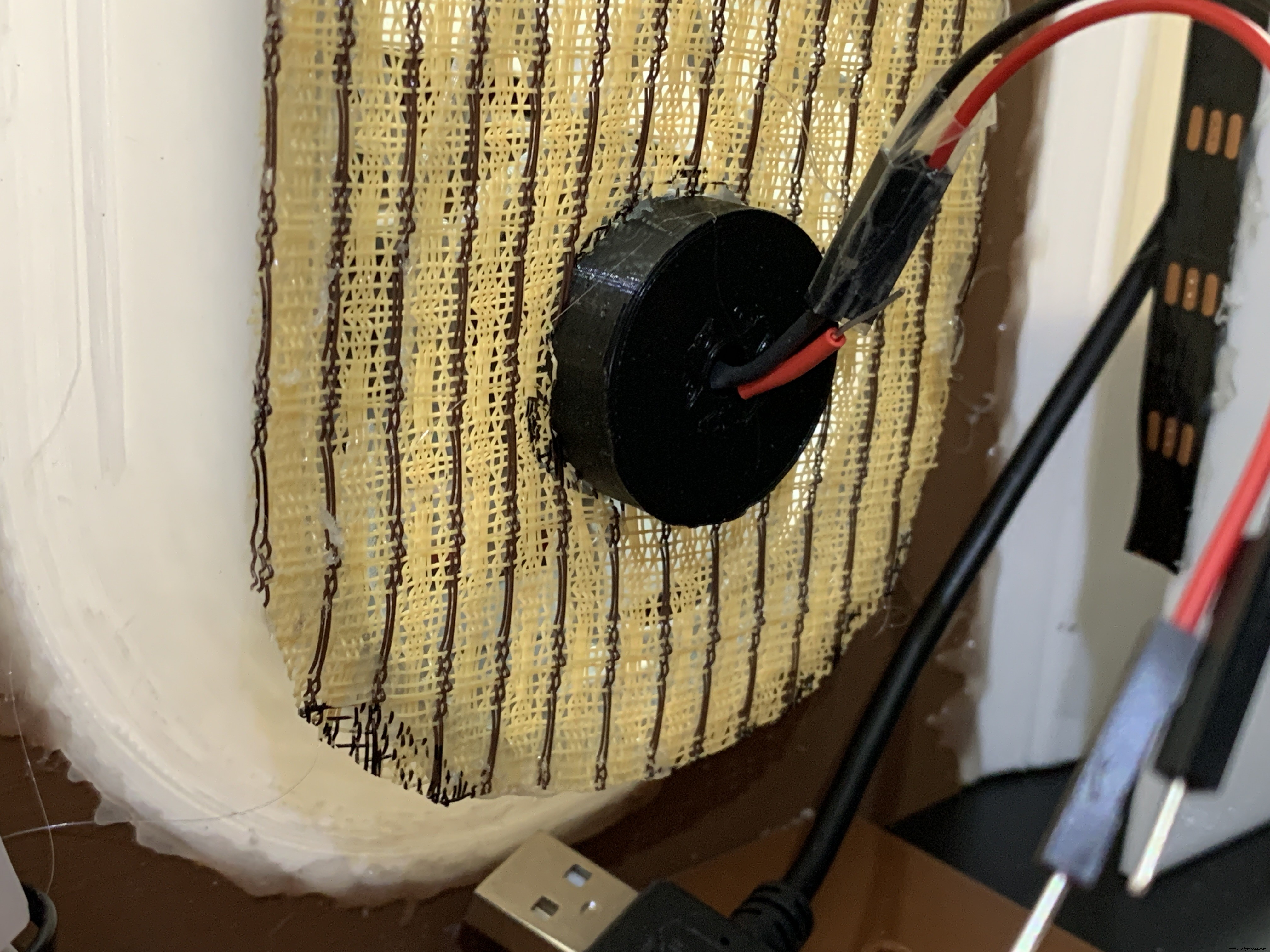
The Grille will be backed with "speaker cloth" to hide the inside of the jukebox. There will be an LED holder behind the Star Light to prevent light bleed, and a hole needs to be cut into the cloth for that.
Cut a piece of speaker cloth large enough to cover the Grille and the edges of the Grille tubes. Use the Star Light LED 3D printed holder as a guide and mark the speaker cloth in a circle for the outside of the holder. Mark a cross in the center of the circle Cut the two lines of the cross to make 4 sections. Cut the rounded part of each section to make a hole for the LED holder.
Mount the color-changing LED mentioned in the section Prepare the Circuit Board/Star Light, above. Insert the LED into the holder and glue it to the Star Light. CA will work well here.
With the LED holder glued in place, fit the speaker cloth over the holder and the Grille. Stretch and glue the edges of the cloth to the Grille Tubes.
Raspberry Pi/IQAudio Pi Digi Amp/Arduino
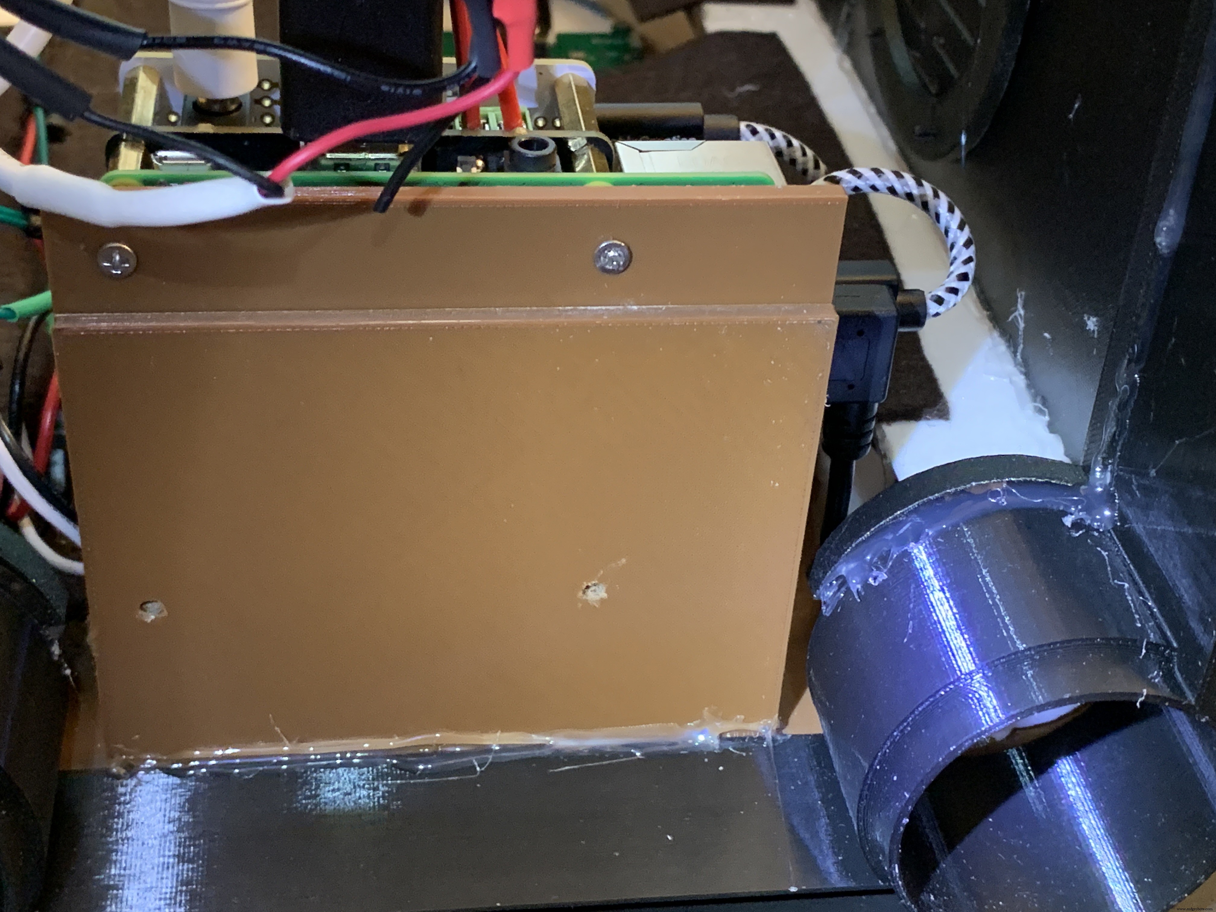
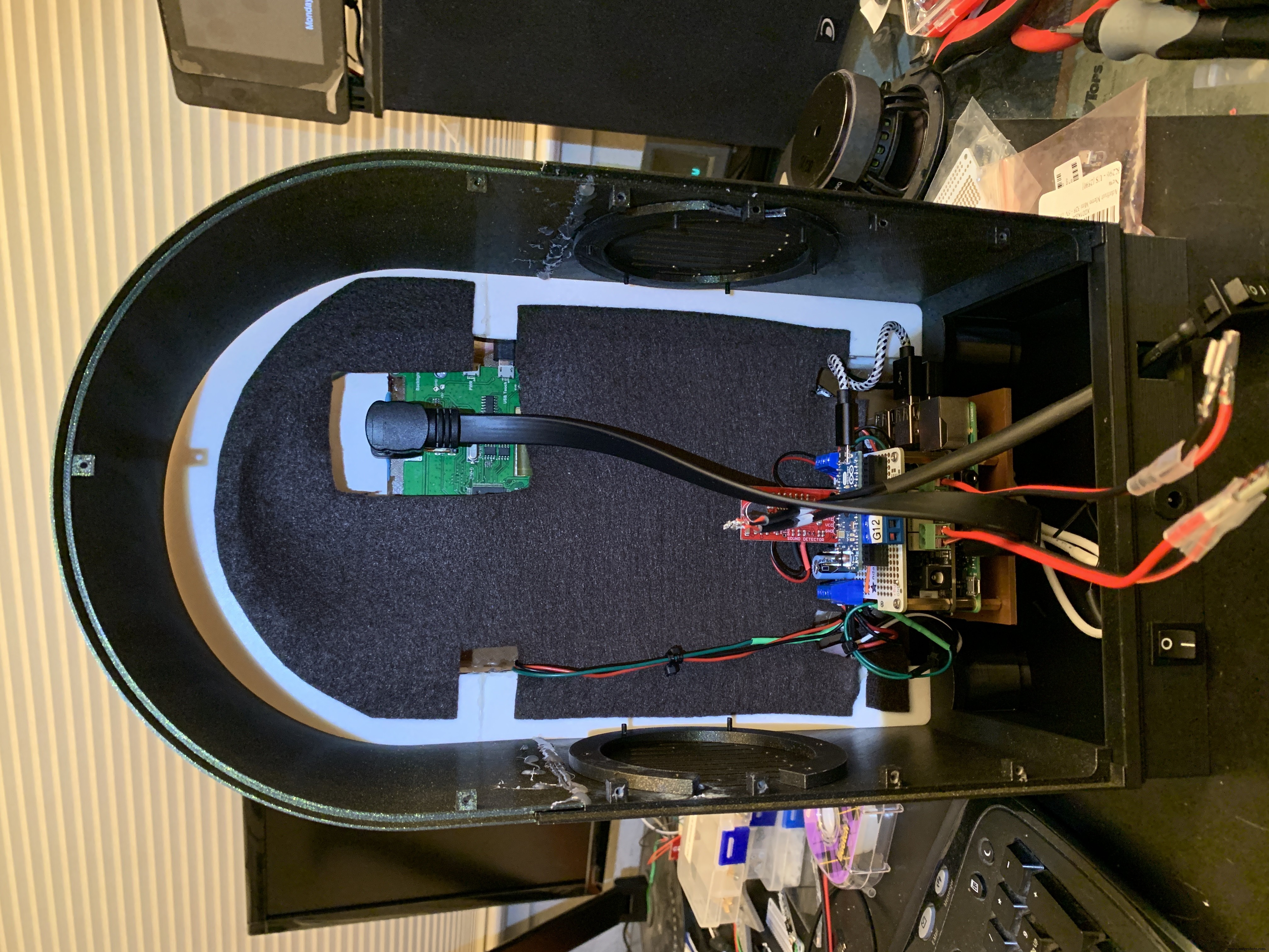
Mount the Pi and other boards (you assembled and tested it in Getting Started, Right ?) onto the mounting plate with screws into the Pi's 5mm bottom standoffs. Plug the LCD HDMI and USB cables into the mounted Pi. There's an additional 6 inch Micro USB to Micro A cable. Plug the Micro end into the Arduino and the other end into the Pi to power the Arduino.
The Star Light +5V and GND plug into the power from the Digi Amp Plus +5V/GND rails.
Adhesive Felt
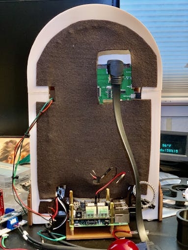
To prevent light bleed, cover the inside with craft felt, which has its own adhesive backing Test fit the felt and cut holes to allow for cables and wires to pass through.
Base with Switches
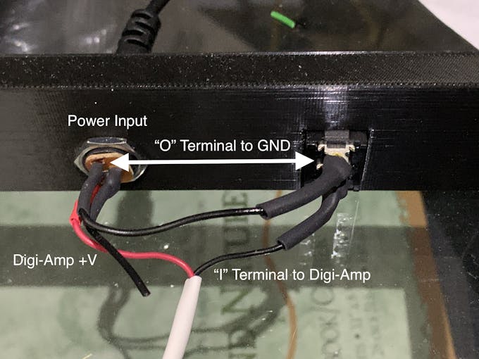
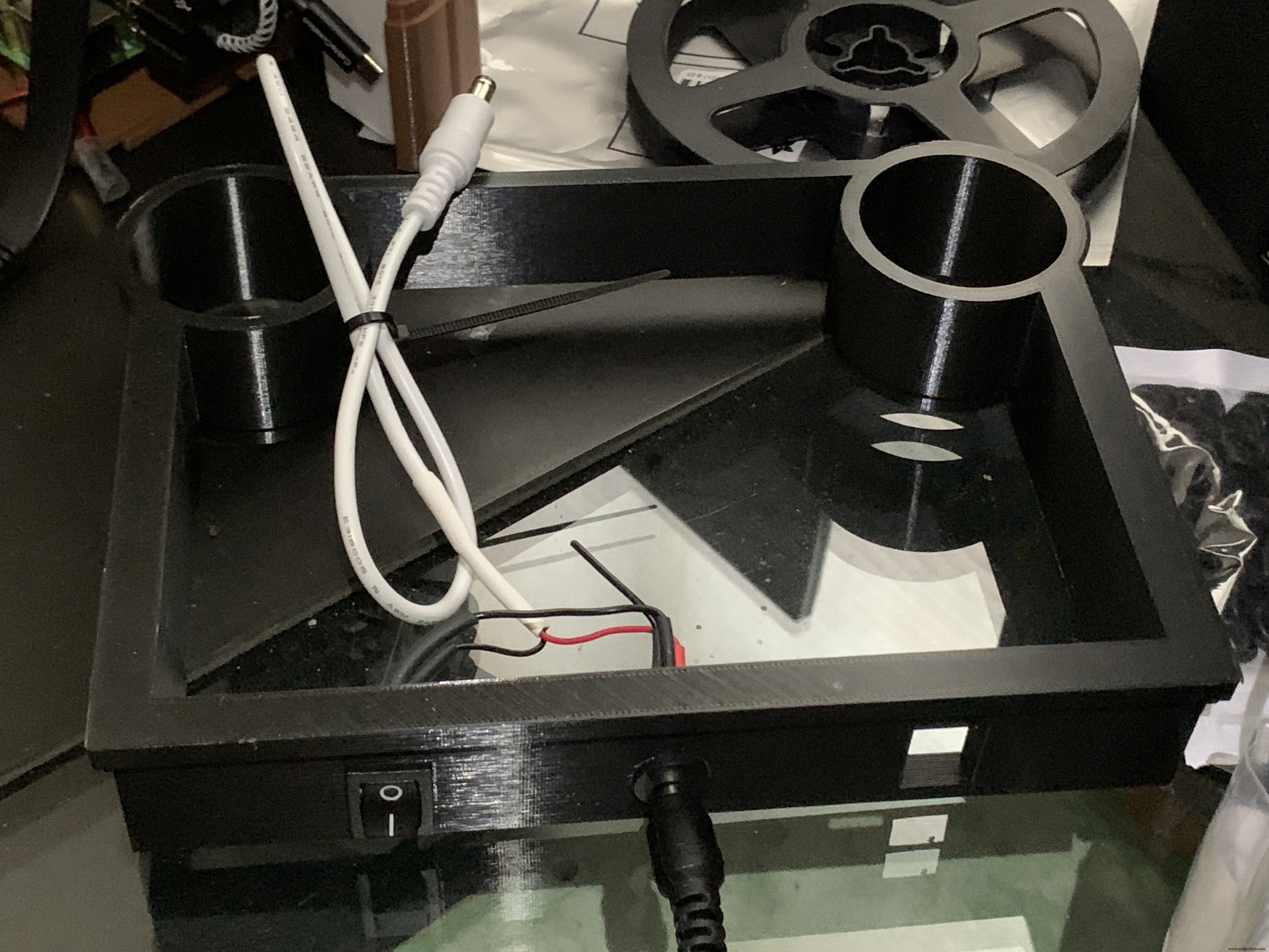
In addition to the Animation Selector Switch, there is an on-off rocker switch that is connected to a panel-mount jack.
Cut one GND (black) wire at least 80 mm long for this switch. Strip the insulating jacket off the power extension cable (white) in pictures about 80 mm long to expose a red and a black wire. Insert the barrel power connector and the on-off rocker switch into the base.
Solder the cut black wire to the terminal marked "O" on one end, the other end to the active GND pin on the barrel power connector. The other terminal "I" is soldered to the GND (black) of the power extension cable for the Digi Amp Plus Finally, the +V (red) of the power extension cable is soldered to the +V terminal of the barrel connector.
Plug the extension connector into the Pi Digi Amp Plus. Glue the Base onto the Bottom and Case.
Speakers
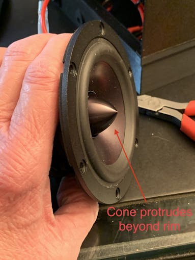
The Dayton Audio RS100-8 speakers have a cone in the middle that prevents them from being mounted flush to a solid grille, as on this jukebox. If you're using these speakers (or some where the center protrudes), you'll have to use a mounting ring (3D file supplied) so the speakers can mount properly.
For the last step of assembly, screw the speakers in with 15 mm M2.5 metal screws and nuts.
Tip: To make assembly easier, mount the speaker rings to the case with the screws pushed in for alignment in the holes. Tack down with hot glue or CA glue. When solid, mount the speakers to the rings.
I had pretty good luck holding the tiny nuts down with my index finger and turning the screw to get the nuts started.
However, there is one screw hole straight back on each side that has very little clearance. It is hard to get the nut started on that screw. Putting blu-tack or tape on the nut may help position it to get it started.
Eventually, I did get all the nuts fastened.
Decorations
There are decorations on top and the two sides of the jukebox, with details in the github 3D Parts List document:
- Neon Tube Red Cover
- Neon Tube Fan Decoration
- Neon Tube Ornament
- Case Joint Cover
- Top Red Ornament
- Top Ornament
Repeat for Left &Right:
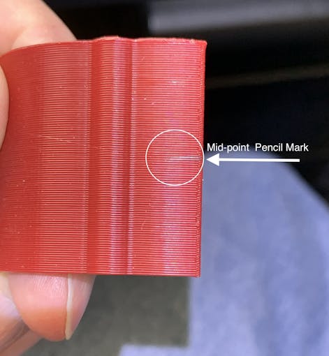
For the Neon Tubes, use a small ruler to mark the halfway point on the side of the Red Cover with a pencil. Then, match that to the Neon Tube joints and glue with CA.
The long Case Joint Cover aligns to the Neon Tube Red Cover and glues down to the case.
Gllue the Fan Decoration and Ornament at the top and bottom of the Red Cover
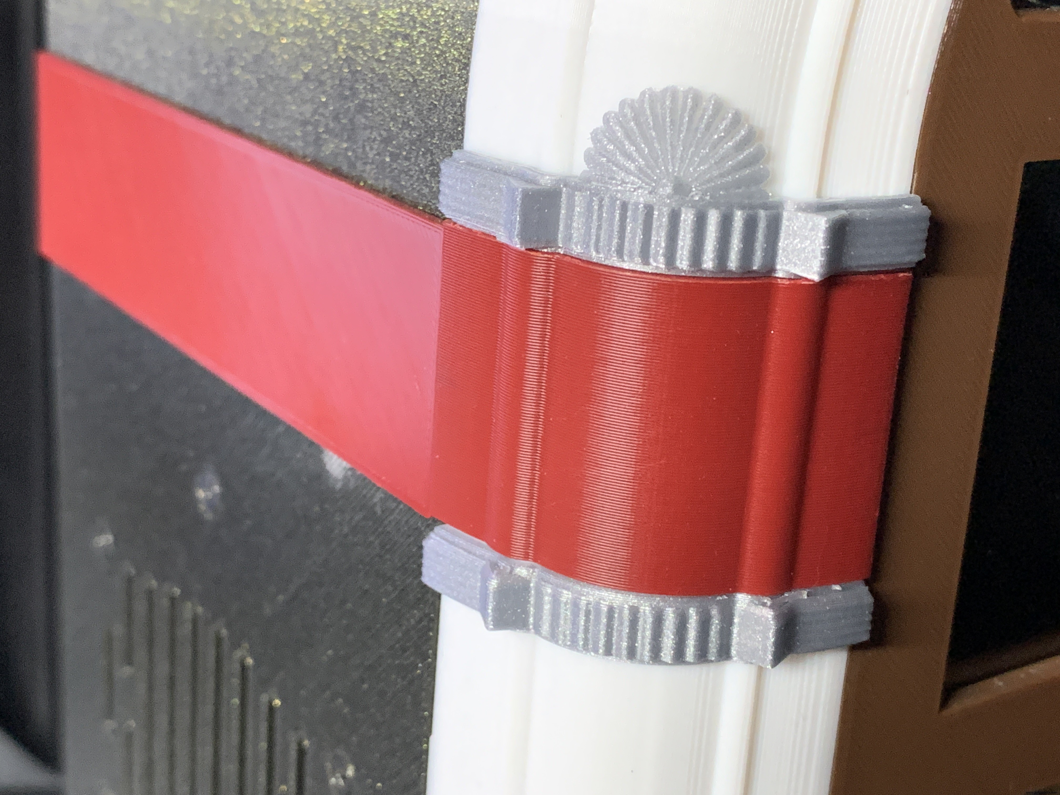
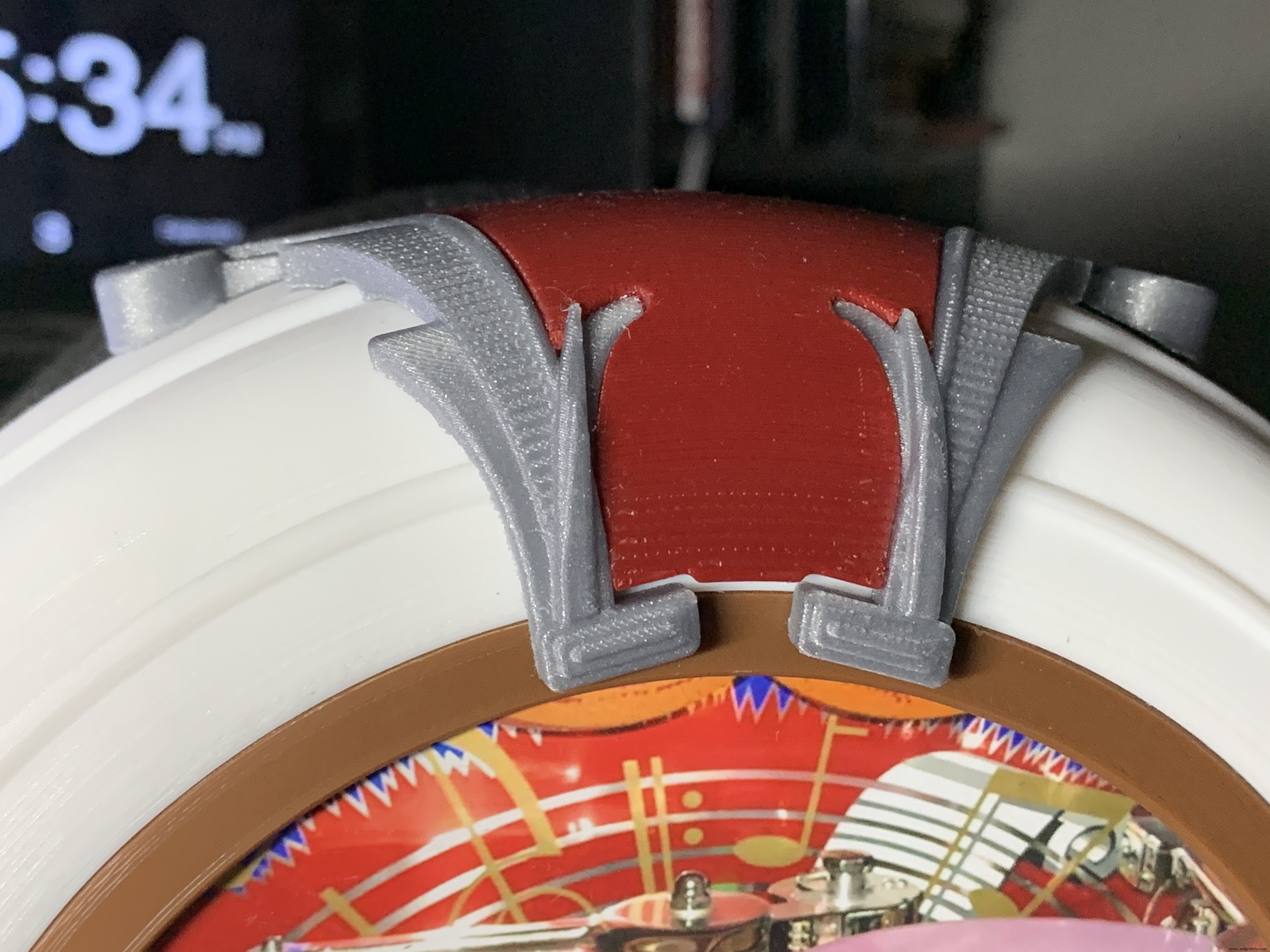
The Top Ornament (2 separate pieces) fits into the Top Red Ornament and is glued together as an assembly.
For alignment, make a pencil mark midway at the top of the Arch and another mark midway on the Top Red Cover. Align these two marks and glue.
Operation
Volumio has a fairly intuitive user interface that's easy to use.
To get started, press/select the 'Home' icon or the 'Browse' button from the 'Playback' window..You'll see something like the image below, depending on what options you have installed.
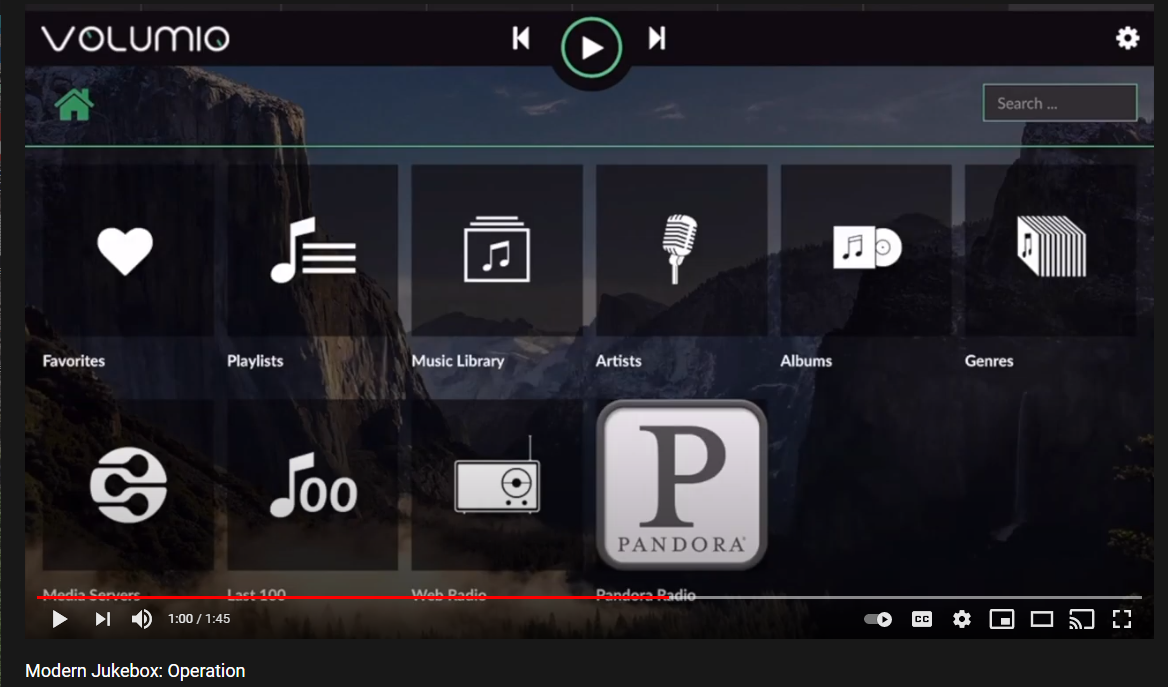
For Pandora and Spotify (paid subscription required), go to Settings/Plugins/Music Services. You can connect to Volumio from AirPlay with the Apple Music player.
Update September 20, 2021:
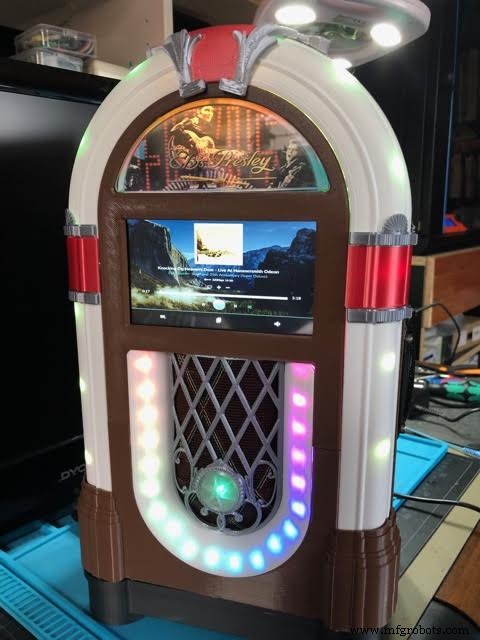
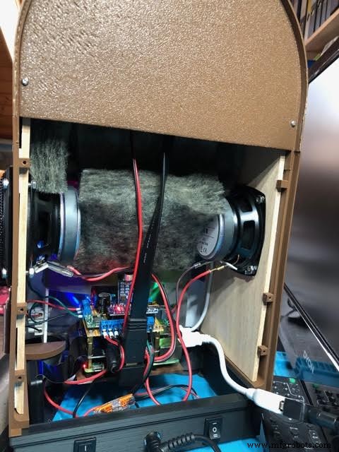
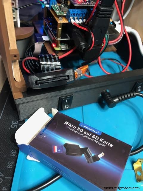
Raimund Trierscheid made a version of the Modern Jukebox, with improvements! Raimund added 5mm wood panels to the sides of the case to hold the heavy speakers and improve the sound.
Here are some photos:
Code
Modern-Jukebox on github
https://github.com/thisoldgeek/Modern-JukeboxAangepaste onderdelen en behuizingen
Fusion 360 design modern_jukebox_r1_v2_dccOE3MSIQ.f3dProductieproces
- Modern niet-mechanisch geheugen
- Jukebox
- Vioolstrijkstok
- Windows 10 IoT Core op Raspberry Pi 2 – Adafruit-sensorgegevens
- Een moderne draai aan FMEA
- De ontwikkeling van moderne kunststoffen
- Sprout:moderne zelfbewaterende plantenbak voor binnen
- UnifiedWater v1
- Mobiele stembus
- Arduino101 / tinyTILE BLE:Match-Making Zonnebril
- Whac-A-Mole (Button Edition)


