


IoT met ESP8266-01 en Arduino
Componenten en benodigdheden
 |
| × | 1 | |||
 |
| × | 1 | |||
 |
| × | 1 | |||
| × | 1 | ||||
 |
| × | 2 | |||
 |
| × | 1 | |||
 |
| × | 1 | |||
 |
| × | 2 | |||
 |
| × | 1 |
Benodigde gereedschappen en machines
| |
| |||
 |
| |||
 |
|
Apps en online services
| ||||
 |
| |||
|
Over dit project
Inleiding
Vandaag zullen we een apparaat bouwen dat verbinding maakt met internet en waarmee de gebruiker zijn/haar huis op afstand kan bedienen via wifi. we zullen het Arduino-bord gebruiken (elk model zal het werk goed doen) met de ESP8266-01 wifi-module om dit apparaat te maken. Laten we beginnen!
Wat is een slim huis?
Werkscenario

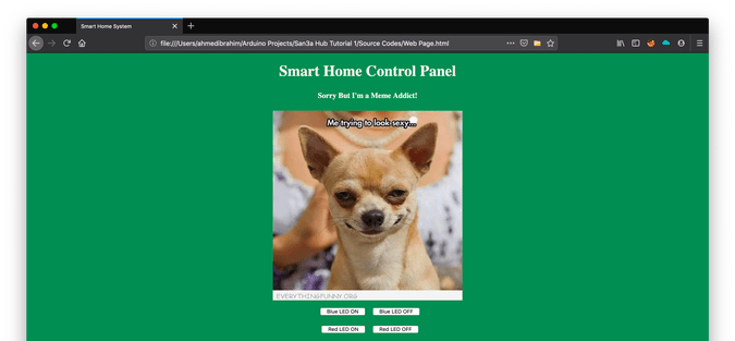
Het Configuratiescherm
We zullen een eenvoudige webpagina bouwen die zal werken als een bedieningspaneel voor de gebruiker waarmee hij elk huishoudelijk apparaat dat op ons systeem is aangesloten, kan bedienen. Om de webpagina te bouwen gebruiken we:
- HTML
- CSS
- Jquery
De ingebouwde hardware
de webpagina stuurt enkele bestellingen naar de ESP8266-01 die werkt als een webserver die is verbonden met het Arduino-bord. En volgens de binnenkomende gegevens zal het Arduino-bord enkele acties ondernemen, zoals het aanzetten van de lamp, het uitschakelen van de tv en in dit deel zullen we gebruiken:
- Arduino
- ESP8266-01
Aan de slag met de ESP8266-01
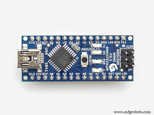
Zoals we eerder zeiden, hebben we ons Arduino-bord nodig om verbinding te maken met internet, maar de Arduino Nano, de versie die we vandaag gebruiken, heeft die functie niet. We zullen dus de ESP8266-01 wifi-module gebruiken om de wifi-functie toe te voegen aan ons kleine Arduino-bord.
er zijn veel ESP wifi-modules die er zijn, welke moet ik kiezen?! Welnu, bijna alle wifi-modules van de ESP-familie zullen het werk goed doen, maar elk heeft zijn eigen kenmerken en specificaties. Ik moedig u aan om naar elk van de specificaties en functies te kijken om de meest geschikte voor uw behoeften te kiezen.
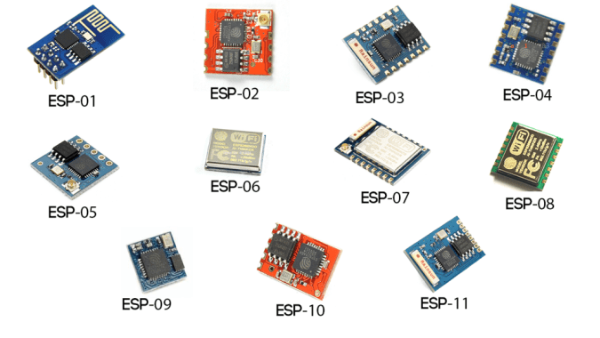
Volgens mijn behoeften vond ik de ESP8266-01 de meest geschikte en dat heeft vele redenen. Het is erg beroemd in de makersgemeenschap. Als gevolg hiervan heeft het een zeer solide online community gekregen waar je een antwoord kunt vinden op bijna elke vraag of probleem dat je tegenkomt met deze geweldige kleine module. Ook is de prijs erg goedkoop (ongeveer $ 1,5).
Het is ook heel gemakkelijk te gebruiken met het Arduino-bord, omdat het een seriële wifi-module is en via seriële communicatie met het Arduino-bord kan communiceren. Het heeft een ingebouwde microcontroller, wat betekent dat je het kunt gebruiken als een stand-alone microcontroller en wifi-module in één combo, wat super cool is. Het heeft ingebouwde twee GPIO's. Alleen met $ 1,5 krijg je al deze functies, wat eigenlijk super cool is. Laten we deze module eens nader bekijken.
ESP8266-01 pinout
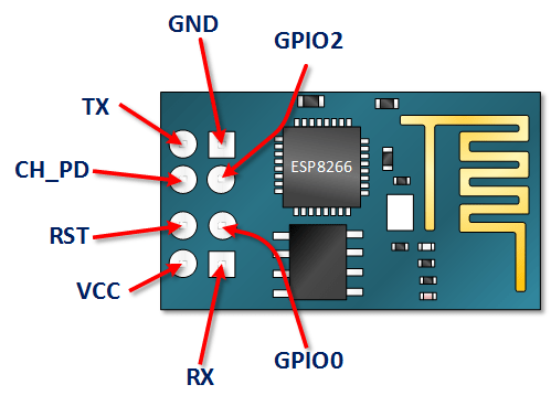
- VCC: aansluiten op +3.3V stroombron. verbind het niet met een 5V-bron, het zal beschadigd raken .
- GND: -ve pin, sluit deze aan op de aarde van uw circuit.
- CH_PD: chip maakt pin mogelijk – Actief HOOG. sluit het aan op een logische waarde HOOG om de module te laten opstarten.
- RST: Chip Reset-pin - Actief LAAG, wanneer deze LAAG wordt getrokken, wordt de module opnieuw ingesteld.
- GPIO0, GPIO2: Algemene input/output pinnen.
- Tx: maak verbinding met de Rx van de microcontroller (Arduino) om seriële communicatie tot stand te brengen.
- Rx: maak verbinding met de Tx van de microcontroller (Arduino) om seriële communicatie tot stand te brengen.
ESP8266-01 Configuratie
Zoals we eerder zeiden, communiceert de ESP8266-01-module met het Arduino-bord via de seriële communicatie, wat betekent dat we het moeten verbinden met de Arduino's seriële pinnen 0, 1 (Tx, Rx). Maar het probleem hier is dat deze pinnen bezet zullen zijn omdat we de Arduino Seriële monitor naast de ESP8266-01 zullen gebruiken voor foutopsporingsdoeleinden. We moeten dus nog twee seriële communicatiepinnen vinden om ze te gebruiken met de ESP8266-01.
Gelukkig heeft Arduino dit gemakkelijk gemaakt. Er is een bibliotheek met de naam "SoftwareSerial", die is ontwikkeld om seriële communicatie op andere digitale pinnen van de Arduino mogelijk te maken, met behulp van software om de functionaliteit te repliceren. Door deze bibliotheek te gebruiken, kan ik bijvoorbeeld de pinnen 2, 3 (SoftwareSerial) instellen als Rx en Tx naast de pinnen 0, 1 (Hardware Serial).
“SoftwareSerial” bibliotheek werkt prima zolang de transmissiesnelheid minder dan 19.200 baud is. Maar er is hier een klein probleem! de ESP8266-01 wifi-module komt uit de fabriek geprogrammeerd om te communiceren met een snelheid van 115, 200 baud, wat op de een of andere manier moeilijk is voor de "SoftwareSerial" -bibliotheek om te communiceren. We moeten onze wifi-module dus opnieuw programmeren om de communicatiesnelheid in te stellen op 9600 baud, wat redelijk goed werkt met de "SoftwareSerial" -bibliotheek. Om dat te doen zullen we enkele "AT-commando's" gebruiken.
De communicatiesnelheid van de ESP8266-01 wijzigen
Eerste stap:upload een leeg programma naar het Arduino-bord
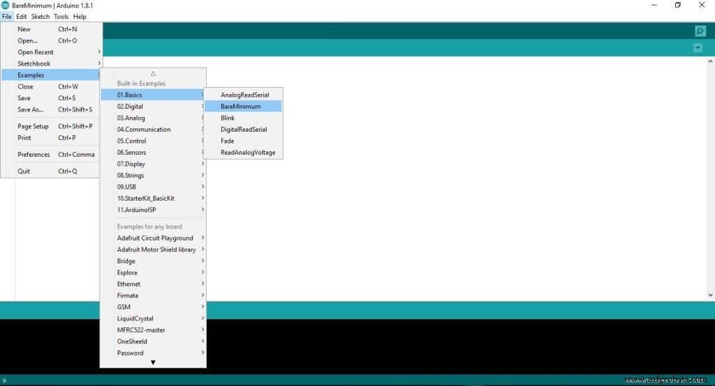
Bij deze stap uploaden we een lege code naar het Arduino-bord. Om er zeker van te zijn dat er niets op de achtergrond wordt uitgevoerd door het Arduino-bord.
Tweede stap:bedrading van de ESP8266-01 met het Arduino-bord
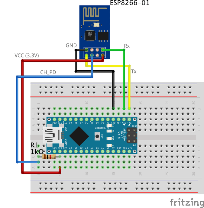
Om de ESP8266-01 opnieuw te configureren en de communicatiesnelheid (baudrate) te wijzigen, gebruiken we de AT-commando's. Simpel gezegd, AT-commando's zijn enkele instructies die worden gebruikt om modems, mobiele telefoons, Bluetooth-modules, wifi-modules, GSM-modules te besturen.
met deze commando's kunnen we basisinformatie krijgen over onze mobiele telefoon of GSM-modules, zoals de naam van de fabrikant, modelnummer, IMEI enzovoort. "AT" is een afkorting voor "ATtention" en het wordt AT-commando's genoemd omdat elk commando begint met "AT". het voorvoegsel "AT" maakt geen deel uit van de opdrachten zelf, het vertelt de module alleen het begin van de opdrachten.
Enkele belangrijke AT-commando's
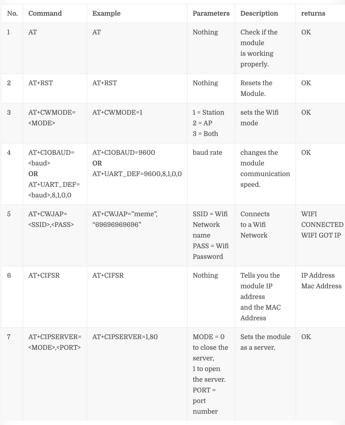
Opdrachtnummer “4” hangt af van uw ESP8266-01-firmwareversie, als deze opdracht niet bij u werkt AT+CIOBAUD= Probeer deze eens AT+UART_DEF=
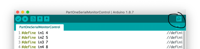
Stap 1:Open de seriële monitor
Stap 2:Stel de communicatiesnelheid in op 115, 200 baud

Zoals we eerder aangaven, komt de ESP van de fabrikant die is geprogrammeerd om te communiceren met een snelheid van 115, 200 baud. Dus we moeten de Arduino-communicatiesnelheid instellen op 115, 200 ook voor de eerste keer alleen dan zullen we dat later veranderen. U moet ook “Beide NL &CR” . selecteren .
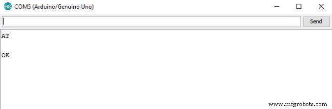
Stap 3:Stuur "AT" en wacht op het antwoord om er zeker van te zijn dat de ESP-module u hoort.
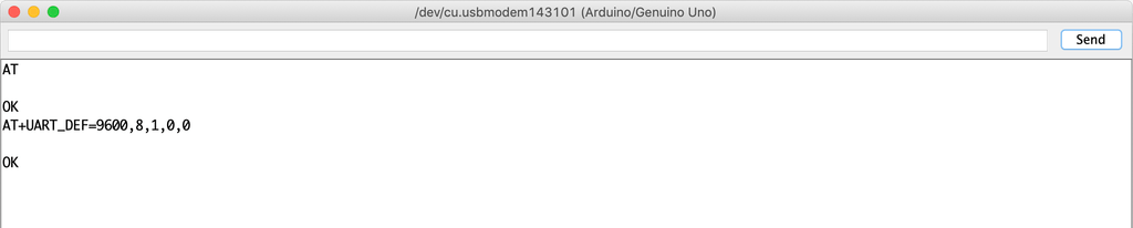
Stap 4:Verander nu de communicatiesnelheid van de ESP8266-01
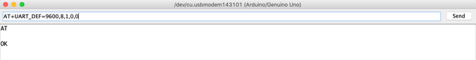
Mijn ESP8266-01 module geladen firmware is 1.6. en dit commando AT+UART_DEF= werkt goed voor mij. Als het niet werkt, probeer dan deze AT+CIOBAUD= . Als het reageert met “OK” nu is de baudrate van uw ESP-module gewijzigd van 115, 200 baud naar 9600 baud. PROFICIAT!
Laten we de communicatiesnelheid van de seriële monitor terugzetten naar 9600 en opnieuw "AT" sturen om te zien of de ESP-module ons kan horen op de nieuwe snelheid (9600) of niet.
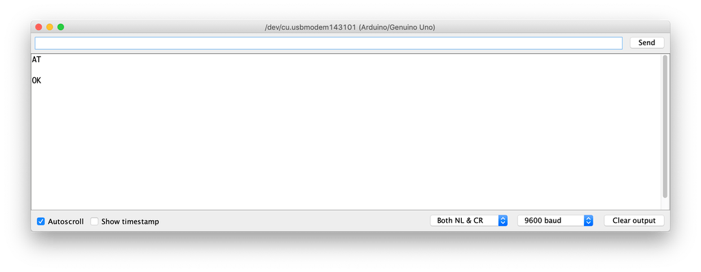
KIJK! het werkt. de ESP8266-01 kan nu communiceren met het Arduino-bord met een baudrate van 9600 in plaats van 115, 200 baudrate.
Laten we nu proberen verbinding te maken met het wifi-netwerk
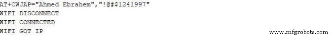
Zodra u op enter drukt, zoekt de ESP8266-01 naar dit netwerk en maakt er verbinding mee. Als het proces slaagt, wordt dit geretourneerd
WIFI VERBONDEN
WIFI KREEG IP
Op dit punt hebben we met succes de communicatiesnelheid van de ESP8266-01 gewijzigd van 115, 200 baud naar 9600 baud. Nu moeten we het configuratiescherm (webpagina) bouwen dat de gebruiker zal gebruiken om zijn huishoudelijke apparaten te bedienen. Dus laten we het bouwen!
Wat is internet?
Eigenlijk is internet een draad die onder de grond is begraven. Het kan glasvezel, koper of zelfs een satelliet zijn, maar internet is gewoon een draad. Elke twee computers die op die draad zijn aangesloten, kunnen communiceren. Als de computer rechtstreeks is aangesloten naar die draad heet het een server en als het niet rechtstreeks op die draad is aangesloten, wordt het een client genoemd .
Server: is een speciale computer met een specifiek besturingssysteem zoals Apache, deze speciale computer slaat een aantal webpagina's, bestanden en databases op zijn schijf op. elke server die is verbonden met internet heeft een uniek IP-adres zoals 172.217.171.228 , het IP-adres is net als een telefoonnummer dat mensen elkaar gemakkelijk kunnen vinden. Aangezien dat IP-adres voor mensen niet erg gemakkelijk te onthouden is. Daarom hebben we het gewoon een naam gegeven google.com (Domeinnaam).
Klant: het is een computer zoals jij en ik elke dag gebruiken, het is indirect verbonden met internet via een internetprovider (ISP) en het heeft ook een uniek IP-adres.
Werkscenario
Het begint eenvoudig met een verzoek dat is verzonden vanuit een webbrowser (client) zoals Google Chrome, Firefox en eindigt met het antwoord dat is ontvangen van de webserver.
Je hebt de website-URL makesomestuff.org in een browser ingevoerd vanaf een computer (client), dan stuurt deze browser een verzoek naar de webserver die de website host, de webserver retourneert vervolgens een antwoord met een HTML-pagina of een ander documentformaat om de browser weer te geven het.
Precies, dat is wat we vandaag moeten doen in ons project. We moeten een verzoek van de webbrowser (client) naar de ESP8266-01 (webserver) sturen die beide zijn verbonden met hetzelfde lokale netwerk. Dit verzoek bevat enkele gegevens die de Arduino vertellen wat hij moet doen om een lamp aan of uit te zetten. Dus laten we de webpagina bouwen!
De webpagina bouwen
Om onze webpagina te bouwen hebben we te maken met HTML, CSS, Javascript. als je nog nooit van deze namen hebt gehoord, maak je geen zorgen, ik heb je.
HTML: Staat voor "HyperText-opmaaktaal", we gebruiken het om de hoofdstructuur van elke webpagina te bouwen. Zoals het toevoegen van enkele knoppen, afbeeldingen, alinea's, kopteksten, tabellen en nog veel meer elementen. het bestaat uit een reeks elementen die de browser vertellen hoe de inhoud van de webpagina moet worden weergegeven. deze elementen worden weergegeven door iets dat tags wordt genoemd.

CSS: Het staat voor Cascading Style Sheet. Na het bouwen van de hoofdstructuur van de webpagina, moet je deze structuur er mooi uit laten zien, hier komt CSS om wat styling te maken. het is een taal die de stijl van een HTML-element beschrijft. het bestaat uit enkele selectors en vertragingsblokken.

Javascript: het is een programmeertaal die we zullen gebruiken om de webpagina interactiever te maken, zoals het toevoegen van enkele animaties, kaarten en het stelt ons in staat om een aantal complexe dingen op de webpagina te maken. We zullen het vandaag voornamelijk gebruiken om een HTTP-verzoek van de client (webbrowser) naar de webserver (ESP8266-01) te sturen om enkele acties uit te voeren, zoals het in- of uitschakelen van een gloeilamp.

Bouw de webpaginastructuur
Om de komende uitleg gemakkelijk te begrijpen, raad ik aan deze coole te lezen HTML-intro .
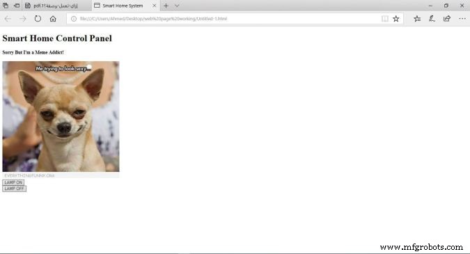
Zoals we zien, is ons configuratiescherm heel eenvoudig, het bevat twee koppen, elk met een ander formaat, één afbeelding en twee knoppen, één om een LED in te schakelen en de tweede om deze uit te schakelen.
Code
Smart Home-systeem Smart Home-bedieningspaneel
Sorry maar Ik ben een Meme-verslaafde!

Code Uitleg
- : verklaring definieert dat dit document een HMTL5-document is.
- : het hoofdelement van een HTML-pagina.
- : element bevat meta-informatie over de pagina.
:</strong> element specificeert de titel van het document. deze titel verschijnt op het browsertabblad van de webpagina.</li> <li><strong><body>:</strong> element bevat de zichtbare webpagina-inhoud.</li> <li><strong><h1>:</strong> element definieert een groot element.</li> <li><strong><h4>:</strong> element definieert een kleinere kop. wanneer de koptekstwaarde afneemt, wordt het lettertype kleiner.</li> <li><strong><img>:</strong> element voegt een afbeelding toe aan de webpagina. de afbeelding die u wilt weergeven moet zich in dezelfde projectmap bevinden.</li> <li><strong><br>:</strong> verplaats de cursor naar een nieuwe regel.</li> <li><strong><button>:</strong> element voegt een knop toe aan de pagina-inhoud.</li> </ul> <p> Elke knop op onze webpagina heeft twee zeer belangrijke kenmerken:de <code>id</code> , en de <code>klasse</code> attributen. we zullen het hebben over waarom we deze twee waarden hebben toegewezen aan de knoppen in de uitleg van de JQuery-code.</P> <h3 id='toc-styling-the-web-page-12'> <p> <p> </P> </P> De webpagina stylen</h3> <p> <strong><em>Om de komende uitleg gemakkelijk te begrijpen, raad ik aan deze coole </em> te lezen </strong> <strong><em>CSS-intro</em> </strong> <strong><em>.</em> </strong> </P> <img loading='lazy' src="https://www.mfgrobots.com/article/uploadfiles/202112/2021122812180042.jpg?auto=compress%2Cformat&w=680&h=510&fit=max" /></figure> <p> Nu ziet de webpagina er mooier uit (NIET TE VEEL xD), we hebben hem een koele groene achtergrondkleur gegeven, we hebben de pagina-inhoud gecentreerd uitgelijnd en we hebben de lettertypekleur en de lettertypefamilie van de kopteksten gewijzigd, waardoor de webpagina levendiger is geworden. We gebruikten CSS om al deze stylingsdingen te doen.</P> <p> <strong>Code</strong> </P> <pre><code><!DOCTYPE html> <html> <head> <title>Smart Home-systeem Smart Home-configuratiescherm
Sorry, maar ik ben een Meme-verslaafde!
Code Uitleg
We hebben enkele regels code toegevoegd om onze webpagina er mooier uit te laten zien. We hebben
style="background-color:seagreen; color:seashell; text-align:center;"toegevoegd in het lichaam tag om alle webpagina-inhoud in het midden van de pagina te maken en om de achtergrondkleur in te stellen op zeegroen ook om de letterkleur in te stellen op zeeschelp .We hebben ook
style="margin:10px;". toegevoegd binnen de twee button-tags om een marge van 10 pixels rond de vier zijden van elke knop in te stellen.
Een verzoek naar de webserver sturenOm de komende uitleg gemakkelijk te begrijpen, raad ik aan dit coole boek te lezen JQuery-intro .
Nu, na het bouwen van onze webpaginastructuur en het stylen ervan, moeten we wat functionaliteit toevoegen aan de twee knoppen die we eerder op de webpagina hebben toegevoegd. we hebben nodig dat wanneer de gebruiker op de knop "LAMP AAN" klikt, zijn / haar browser een verzoek stuurt met enkele unieke gegevens naar de server (ESP8266-01) deze unieke gegevens vertellen de Arduino om de lamp in te schakelen. Hetzelfde met de tweede knop "LAMP UIT" wanneer de gebruiker erop klikt, zal de browser een verzoek sturen met enkele unieke gegevens naar de server (ESP8266-01). Deze unieke gegevens vertellen de Arduino om de lamp uit te schakelen. Laten we de code eens bekijken.
Smart Home-systeem Smart Home-bedieningspaneel
Sorry, maar ik ben een Meme-verslaafde!
Code Uitleg
Eerste dingen Eerst moeten we de JQuery-bibliotheek in onze code importeren. Dus hebben we deze regel toegevoegd aan de head tag .
Alle magie gebeurt in dit interessante deel.
$(".button").click(function () {
Wanneer de gebruiker op een knop klikt die is gekoppeld aan de klasse “knop” , activeer de volgende functie.
var p =$(this).attr('id');
Haal de waarde op van het kenmerk van de aangeklikte knop “id” en bewaar het in de “p” variabel.
pin:p
Zet de variabele "p"-waarde in een woordenboek (sleutel-waarde), de sleutel is "pin" en de waarde is de variabele "p"-waarde.
$.get("http://172.20.10.11:80/", { pin:p });});
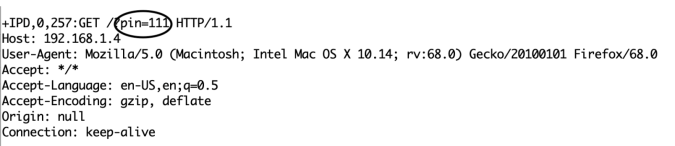
Stuur vervolgens een GET-verzoek naar de webserver waarvan het IP-adres "172.20.10.11" is. deze KRIJG request bevat de waarde van het attribuut id ingedrukte knop.
Als de gebruiker op de knop "LAMP AAN" heeft gedrukt, is deze id-waarde 111, dus de kop van het GET-verzoek bevat enkele gegevens zoals deze pin=111 . kijk naar de volgende figuur!
Aan de andere kant, als de gebruiker op de knop "LAMP UIT" heeft gedrukt, bevat het verzoek deze gegevens pin=110 .
Codelogica
Ik weet dat je nu vraagt waarom hij in godsnaam voor 111 heeft gekozen en 110 specifiek? Ok, Lemme antwoord je fam. Eigenlijk is het nummer 111 en 110 splitst in twee delen.
- Deel één: zijn de eerste twee cijfers die in beide gevallen "11" zijn, het verwijst naar het Arduino-pinnummer waarop de belasting die ik moet bedienen is aangesloten.
- Deel twee: is het derde getal dat verandert tussen 1 en 0, afhankelijk van de aangeklikte knop. En het verwijst naar de pinstatus (AAN of UIT).
In de Arduino-code zullen we deze gegevens ontvangen en deze twee delen van elkaar scheiden en elk deel opslaan in een andere variabele, deel één in variabele
pinNumberen het tweede deel in variabelepinState, dan zullen we deze eenvoudige regel code schrijven om de aangesloten belasting te besturendigitalWrite(pinNumber, pinState);
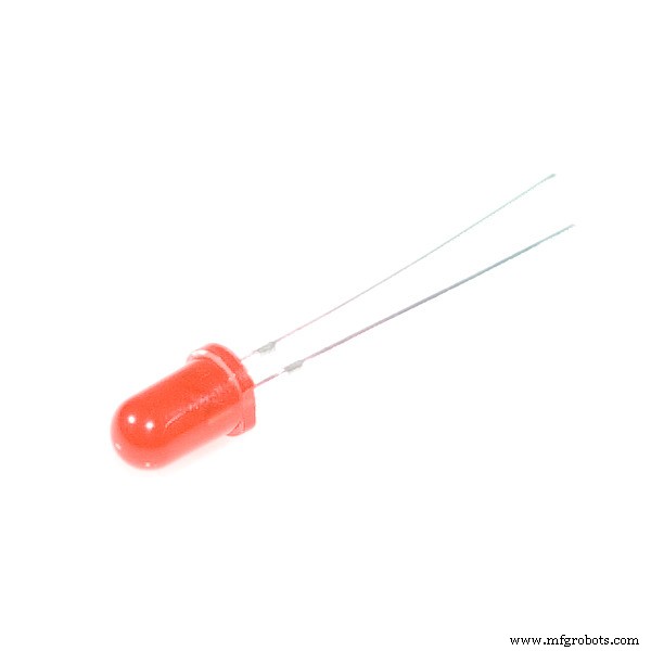
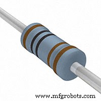
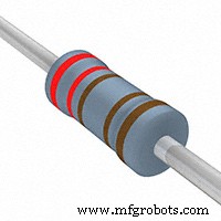
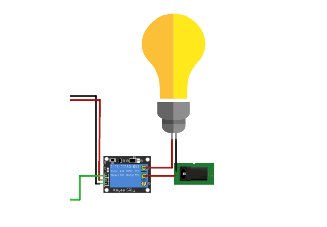
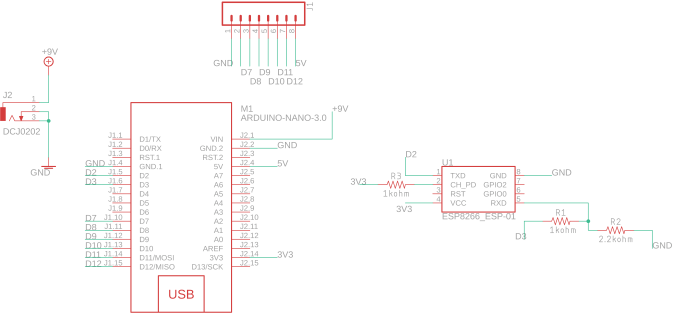
De belasting aansluitenNu moeten we de belasting verbinden met het Arduino-bord om het te bedienen. Voordat we een hoogspanningsapparaat zoals de airconditioner of zelfs de tv aansluiten, moeten we ons circuit en de code testen met wat laagspanningsdingen zoals LED's om er zeker van te zijn dat alles goed werkt. Hier is het bedradingsschema
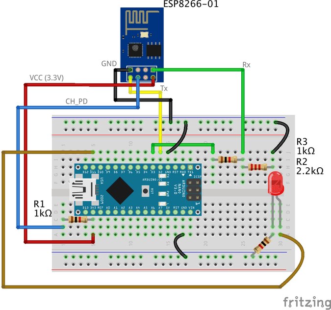
De bedrading is vrij eenvoudig, we verbinden de positieve poot van de LED met de Arduino digitale pin 11 en de negatieve poot met de GND via een weerstand van 1k ohm.
Arduino-code
#include//inclusief de SoftwareSerial-bibliotheek stelt u in staat om de pincode te gebruiken. 2,3 als Rx, Tx. SoftwareSeriële esp8266 (2,3); // stel de Rx ==> Pin 2 in; TX ==> Pin3. #define serialCommunicationSpeed 9600 // <=========definieer een constante genaamd "serialCommunicationSpeed" met een waarde 9600. het verwijst naar de software en hardware seriële communicatiesnelheid (baudrate). #define DEBUG true // maak een constante met de naam "DEBUG" en de waarde is true. we zullen het later gebruiken. int rode LED =12; // wijs een variabele toe met de naam "redLED" met een geheel getal van 12, het verwijst naar de pin waarop de rode LED is aangesloten. int blauwe LED =11; // wijs een variabele toe met de naam "blueLED" met een geheel getal van 11, het verwijst naar de pin waarop de blauwe LED is aangesloten. void setup () { pinMode (rode LED, OUTPUT); // stel het pinnummer 12 in als een uitvoerpin. pinMode (blauwe LED, UITGANG); // stel het pinnummer 11 in als een uitvoerpin. digitalWrite (rode LED, LAAG); // schakel de rode LED uit aan het begin van het programma. digitalWrite (blauwLED, HOOG); // zet de blauwe LED aan aan het begin van het programma. Serial.begin(serialCommunicationSpeed); //begin de hardware seriële communicatie (0, 1) met snelheid 9600. esp8266.begin (serialCommunicationSpeed); //begin de software seriële communicatie (2, 3) op snelheid 9600. InitWifiModule(); // Roep deze door de gebruiker gedefinieerde functie "InitWifiModule()" aan om een communicatie tussen de ESP8266 en uw toegangspunt (Home Router of zelfs uw mobiele hotspot) te initialiseren. digitalWrite (blauw LED, LAAG); // nadat de initialisatie met succes is voltooid, schakelt u de blauwe LED uit (slechts een indicator). } void loop() //our main program, some fun are about to start) { if(esp8266.available()) //if there's any data received and stored in the serial receive buffer, go and excute the if-condition body. If not, dont excute the if-condition body at all. { if(esp8266.find("+IPD,")) //search for the "+IPD," string in the incoming data. if it exists the ".find()" returns true and if not it returns false. { delay(1000); //wait 1 second to fill up the buffer with the data. int connectionId =esp8266.read()-48; //Subtract 48 because the read() function returns the ASCII decimal value. And 0 (the first decimal number) starts at 48. We use it to convert from ASCI decimal value to a character value. esp8266.find("pin="); //Advance the cursor to the "pin=" part in the request header to read the incoming bytes after the "pin=" part which is the pinNumer and it's state. int pinNumber =(esp8266.read()-48)*10; //read the first Byte from the Arduino input buffer(i.e. if the pin 12 then the 1st number is 1) then multiply this number by 10. So, the final value of the "pinNumber" variable will be 10. pinNumber =pinNumber + (esp8266.read()-48); //read the second Byte from the Arduino input buffer(i.e. if the pin number is 12 then the 2nd number is 2) then add this number to the first number. So, the final value of the "pinNumber" variable will be 12. int statusLed =(esp8266.read()-48); //read the third byte from the Arduino input buffer. then save it inside the "statusLed" variable. At any case, it will be 1 or 0. digitalWrite(pinNumber, statusLed); //then turn the LED at "pinNumber" on or off depending on the "statusLed" variable value. Serial.println(connectionId); //print the "connectionId" value on the serial monitor for debugging purposes. Serial.print(pinNumber); //print the "pinNumber" value on the serial monitor for debugging purposes. Serieel.print(" "); //print some spaces on the serial monitor to make it more readable. Serial.println(statusLed); //print the "statusLed" value on the serial monitor for debugging purposes. String closeCommand ="AT+CIPCLOSE="; //close the TCP/IP connection. closeCommand+=connectionId; //append the "connectionId" value to the string. closeCommand+="\r\n"; //append the "\r\n" to the string. it simulates the keyboard enter press. sendData(closeCommand,1000,DEBUG); //then send this command to the ESP8266 module to excute it. } } } /****************************************************************************************************************************************************************************************** * Name:sendData * Description:this Function regulates how the AT Commands will ge sent to the ESP8266. * * Params:command - the AT Command to send * - timeout - the time to wait for a response * - debug - print to Serial window?(true =yes, false =no) * * Returns:The response from the esp8266 (if there is a reponse) */ String sendData(String command, const int timeout, boolean debug) { String response =""; //initialize a String variable named "response". we will use it later. esp8266.print(command); //send the AT command to the esp8266 (from ARDUINO to ESP8266). long int time =millis(); //get the operating time at this specific moment and save it inside the "time" variable. while( (time+timeout)> millis()) //excute only whitin 1 second. { while(esp8266.available()) //is there any response came from the ESP8266 and saved in the Arduino input buffer? { char c =esp8266.read(); //if yes, read the next character from the input buffer and save it in the "response" String variable. response+=c; //append the next character to the response variabl. at the end we will get a string(array of characters) contains the response. } } if(debug) //if the "debug" variable value is TRUE, print the response on the Serial monitor. { Serial.print(response); } return response; //return the String response. } /****************************************************************************************************************************************************************************************** * Name:InitWifiModule * Description:this Function gives the commands that we need to send to the sendData() function to send it. * * Params:Nothing. * * Returns:Nothing (void). */ void InitWifiModule() { sendData("AT+RST\r\n", 2000, DEBUG); //reset the ESP8266 module. //delay(1000); sendData("AT+CWJAP=\"PUT YOUR SSID\",\"PUT YOUR PASSWORD\"\r\n", 2000, DEBUG); //connect to the WiFi network. delay (3000); sendData("AT+CWMODE=1\r\n", 1500, DEBUG); //set the ESP8266 WiFi mode to station mode. vertraging (1000); sendData("AT+CIFSR\r\n", 1500, DEBUG); //Show IP Address, and the MAC Address. vertraging (1000); sendData("AT+CIPMUX=1\r\n", 1500, DEBUG); //Multiple conections. vertraging (1000); sendData("AT+CIPSERVER=1,80\r\n", 1500, DEBUG); //start the communication at port 80, port 80 used to communicate with the web servers through the http requests. } code explanation
the code is pretty straightforward, we implemented two different functions
InitWifiModule()andsendData()The
sendData()function job is regulating how the AT commands will get sent to the ESP8266-01 module.the
InitWifiModule()function job is to provide thesendData()function the AT commands that we need to send to the ESP8266-01.in the
loop()function we read the income HTTP request header and search for the “+IPD, ” which means that the request has successfully arrived, then we read the pin value which it will be “111” if the user clicked the “LAMP ON” button and “110” if the user clicked “LAMP OFF” button.Don’t forget to put your wifi SSID and Password in the Arduino code line no. 103
sendData("AT+CWJAP=\"PUT YOUR SSID\",\"PUT YOUR PASSWORD\"\r\n", 2000, DEBUG);For more code explanation please read the comments in the code, it’s well documented
Hoe het werktAfter uploading the code to the Arduino board, open the Serial monitor and read the responses that the ESP module is sending.
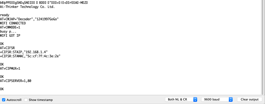
at the beginning of the program, if you see something like the previous figure with “OK” at the end of the page, it means that the ESP8266-01 module is successfully connected to your wifi (Access point) and got an IP and MAC address. Now, you can open your fancy web page and try to control some stuff 😉
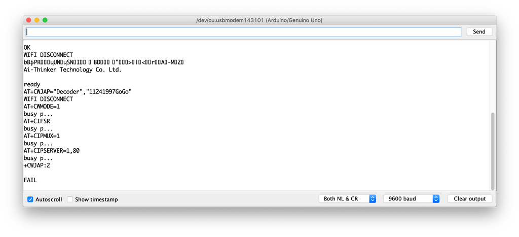
But, if you see something like the previous figure with a “FAIL” or “ERROR” at the end of the page, it means that your ESP module cant connect to your wifi (Access point) for some reasons, try to check if entered the right SSID and password for your network.
Adding a High Voltage LoadAfter we tested our code and got sure that everything is working like a charm, we need to replace this boring LED with a High voltage load like an air conditioner, TV or a light bulb. But to control all of these high voltage appliances we have to deal with relays .
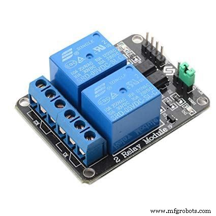
What’s and why relays? Ok, the relay is a mechanical switch, which is toggled on or off by energizing a coil. it’s mainly used to control a high powered circuit using a low power signal (5V or 0V). So we can control a high powered device like an air conditioner or an AC lamp turning it on or off only by a 5V or 0V signal. Which is amazing!
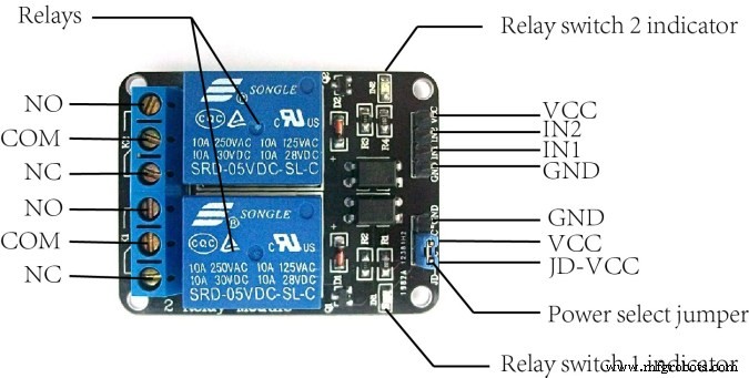
The Two-channel relay module has two control pins(IN1, IN2) these pins should get connected to two Arduino digital pins to control the state of the two coils, closes or opens the load circuit.
At the opposite side of the relay module, the COM(common) should get connected to one end of the load. the other end of the load is either connected to the NC(Normally Close) or NO(Normally open) , if connected to the NO the load remains Disconnected before trigger and vice versa.
Wiring Diagram
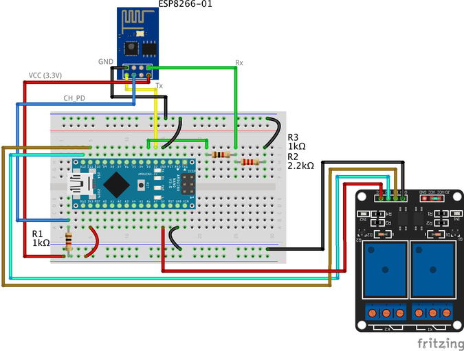
As you see, we are using a two-channel relay module that gives us the ability to control two different AC loads. We are connecting the first relay at digital output pin11(Arduino) and the second relay to digital output pin 12(Arduino)
We will make a small modification to our web page, we will add another two buttons(ON and OFF) to control the second connected load.
Smart Home System Smart Home Control Panel
Sorry But I'm a Meme Addict!
How It Works
Just like the last trial, You upload the Arduino code to the board (if not uploaded yet) and open the serial monitor and make sure that your ESP module is connected successfully to your access point and got an IP and MAC address.
Then open your fancy web page and start controlling your stuff 😉
Make it more professional!What about transferring our breadboard circuit to a professional printed circuit board (PCB) to make our project more rigid and solid, I designed the project circuit using Autodesk Eagle software. all the PCB files are open-source you can access it from this link:https://www.pcbway.com/project/shareproject/IoT_Using_Arduino_and_ESP8266_01.html
Because we love open source 😉
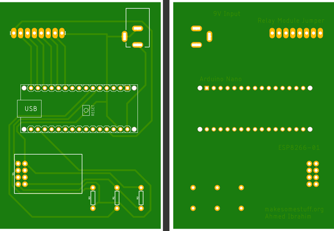
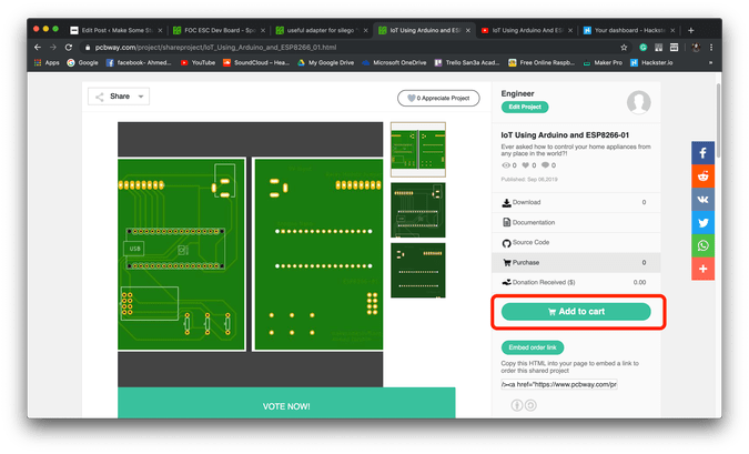
You can order your own PCB From PCBWay company these guys have a very good reputation in this field and they ship to more than 170 countries around the world with reasonable prices. all you have to do is to open the project PCB files link and press “Add to cart”. That’s it!
Problemen oplossenif your ESP Module is successfully connected to your access point but there is no action happens when you click the web page buttons
- make sure that you are sending the request from your web browser from port 80(HTTP). example:
$.get("http://192.168.1.4:80/"- make sure that your PC or Laptop and the ESP module is connected to the same Access point.
- In Jquery code, make sure that you wrote the right ESP module IP address.
- Make sure that you are connecting the load at Arduino digital pins 11 and 12.
- Don’t forget to save the Web page code file after any change or modification, and reload the web page in the web browser after any code modification to take effect.
FinalWe are done! in today’s tutorial, we learned how to build a simple web page using HTML, CSS, and jquery. Also, we learned how to control an AC load wirelessly from a web-based control panel, and how to use the awesome ESP8266-01 Wifi module with the Arduino board.
you wanna see more Tutorials and open source projects you can also visit my blog www.makesomestuff.org
Lastly, if you have any questions drop it in the comments section below, I will be more than happy to hear from you 😉
Code
- Web Page
- Final Arduino Code
Web PageHTML
Smart Home System Smart Home Control Panel
Sorry But I'm a Meme Addict!
Final Arduino CodeArduino
#include
//including the SoftwareSerial library will allow you to use the pin no. 2,3 as Rx, Tx.SoftwareSerial esp8266(2,3); //set the Rx ==> Pin 2; TX ==> Pin3.#define serialCommunicationSpeed 9600 // <=========define a constant named "serialCommunicationSpeed" with a value 9600. it referes to the Software and hardware serial communication speed(baud rate).#define DEBUG true //make a constant named "DEBUG" and it's value true. we will use it later.int redLED =12; //assign a variable named "redLED" with an integer value 12, it refers to the pin which the red LED is connected on.int blueLED =11; //assign a variable named "blueLED" with an integer value 11, it refers to the pin which the blue LED is connected on.void setup(){ pinMode(redLED,OUTPUT); //set the pin number 12 as an output pin. pinMode (blauwe LED, UITGANG); //set the pin number 11 as an output pin. digitalWrite(redLED,LOW); //turn the red LED off at the beginning of the program. digitalWrite (blauwLED, HOOG); //turn the blue LED on at the beginning of the program. Serial.begin(serialCommunicationSpeed); //begin the Hardware serial communication (0, 1) at speed 9600. esp8266.begin(serialCommunicationSpeed); //begin the software serial communication (2, 3) at speed 9600. InitWifiModule(); //call this user-defined function "InitWifiModule()" to initialize a communication between the ESP8266 and your access point (Home Router or even your mobile hotspot). digitalWrite (blauw LED, LAAG); //after finishing the initialization successfully, turn off the blue LED (just an indicator).}void loop() //our main program, some fun are about to start){ if(esp8266.available()) //if there's any data received and stored in the serial receive buffer, go and excute the if-condition body. If not, dont excute the if-condition body at all. { if(esp8266.find("+IPD,")) //search for the "+IPD," string in the incoming data. if it exists the ".find()" returns true and if not it returns false. { delay(1000); //wait 1 second to fill up the buffer with the data. int connectionId =esp8266.read()-48; //Subtract 48 because the read() function returns the ASCII decimal value. And 0 (the first decimal number) starts at 48. We use it to convert from ASCI decimal value to a character value. esp8266.find("pin="); //Advance the cursor to the "pin=" part in the request header to read the incoming bytes after the "pin=" part which is the pinNumer and it's state. int pinNumber =(esp8266.read()-48)*10; //read the first Byte from the Arduino input buffer(i.e. if the pin 12 then the 1st number is 1) then multiply this number by 10. So, the final value of the "pinNumber" variable will be 10. pinNumber =pinNumber + (esp8266.read()-48); //read the second Byte from the Arduino input buffer(i.e. if the pin number is 12 then the 2nd number is 2) then add this number to the first number. So, the final value of the "pinNumber" variable will be 12. int statusLed =(esp8266.read()-48); //read the third byte from the Arduino input buffer. then save it inside the "statusLed" variable. At any case, it will be 1 or 0. digitalWrite(pinNumber, statusLed); //then turn the LED at "pinNumber" on or off depending on the "statusLed" variable value. Serial.println(connectionId); //print the "connectionId" value on the serial monitor for debugging purposes. Serial.print(pinNumber); //print the "pinNumber" value on the serial monitor for debugging purposes. Serieel.print(" "); //print some spaces on the serial monitor to make it more readable. Serial.println(statusLed); //print the "statusLed" value on the serial monitor for debugging purposes. String closeCommand ="AT+CIPCLOSE="; //close the TCP/IP connection. closeCommand+=connectionId; //append the "connectionId" value to the string. closeCommand+="\r\n"; //append the "\r\n" to the string. it simulates the keyboard enter press. sendData(closeCommand,1000,DEBUG); //then send this command to the ESP8266 module to excute it. } }}/******************************************************************************************************************************************************************************************* Name:sendData* Description:this Function regulates how the AT Commands will ge sent to the ESP8266.* * Params:command - the AT Command to send * - timeout - the time to wait for a response * - debug - print to Serial window?(true =yes, false =no)* * Returns:The response from the esp8266 (if there is a reponse)*/String sendData(String command, const int timeout, boolean debug){ String response =""; //initialize a String variable named "response". we will use it later. esp8266.print(command); //send the AT command to the esp8266 (from ARDUINO to ESP8266). long int time =millis(); //get the operating time at this specific moment and save it inside the "time" variable. while( (time+timeout)> millis()) //excute only whitin 1 second. { while(esp8266.available()) //is there any response came from the ESP8266 and saved in the Arduino input buffer? { char c =esp8266.read(); //if yes, read the next character from the input buffer and save it in the "response" String variable. response+=c; //append the next character to the response variabl. at the end we will get a string(array of characters) contains the response. } } if(debug) //if the "debug" variable value is TRUE, print the response on the Serial monitor. { Serial.print(response); } return response; //return the String response.}/******************************************************************************************************************************************************************************************* Name:InitWifiModule* Description:this Function gives the commands that we need to send to the sendData() function to send it.* * Params:Nothing.* * Returns:Nothing (void).*/void InitWifiModule(){ sendData("AT+RST\r\n", 2000, DEBUG); //reset the ESP8266 module. //delay(1000); sendData("AT+CWJAP=\"Decoder\",\"1241997GoGo\"\r\n", 2000, DEBUG); //connect to the WiFi network. delay (3000); sendData("AT+CWMODE=1\r\n", 1500, DEBUG); //set the ESP8266 WiFi mode to station mode. delay (1500); sendData("AT+CIFSR\r\n", 1500, DEBUG); //Show IP Address, and the MAC Address. delay (1500); sendData("AT+CIPMUX=1\r\n", 1500, DEBUG); //Multiple conections. delay (1500); sendData("AT+CIPSERVER=1,80\r\n", 1500, DEBUG); //start the communication at port 80, port 80 used to communicate with the web servers through the http requests.} Schema's
Productieproces
- TinyML-taaldetector-gebaseerd op Edge Impulse &Arduino
- Arduino-gyroscoopspel met MPU-6050
- Arduino digitale dobbelstenen
- ULTRASONE LEVITATION-machine die ARDUINO gebruikt
- DIY voltmeter met Arduino en smartphone
- Hartslagmeter met IoT
- IOT - Smart Jar met ESP8266, Arduino en ultrasone sensor
- Sonar met arduino en weergave op verwerkings-IDE
- LED-helderheid regelen met Bolt en Arduino
- Volledige controle over uw tv met Alexa en Arduino IoT Cloud
- FM-radio met Arduino en RDA8057M