


Word Clock met minutenresolutie van tijd in woorden
Componenten en benodigdheden
 |
| × | 1 |
Over dit project
Meer details over deze build zijn te vinden op mijn site hier:Word Clock
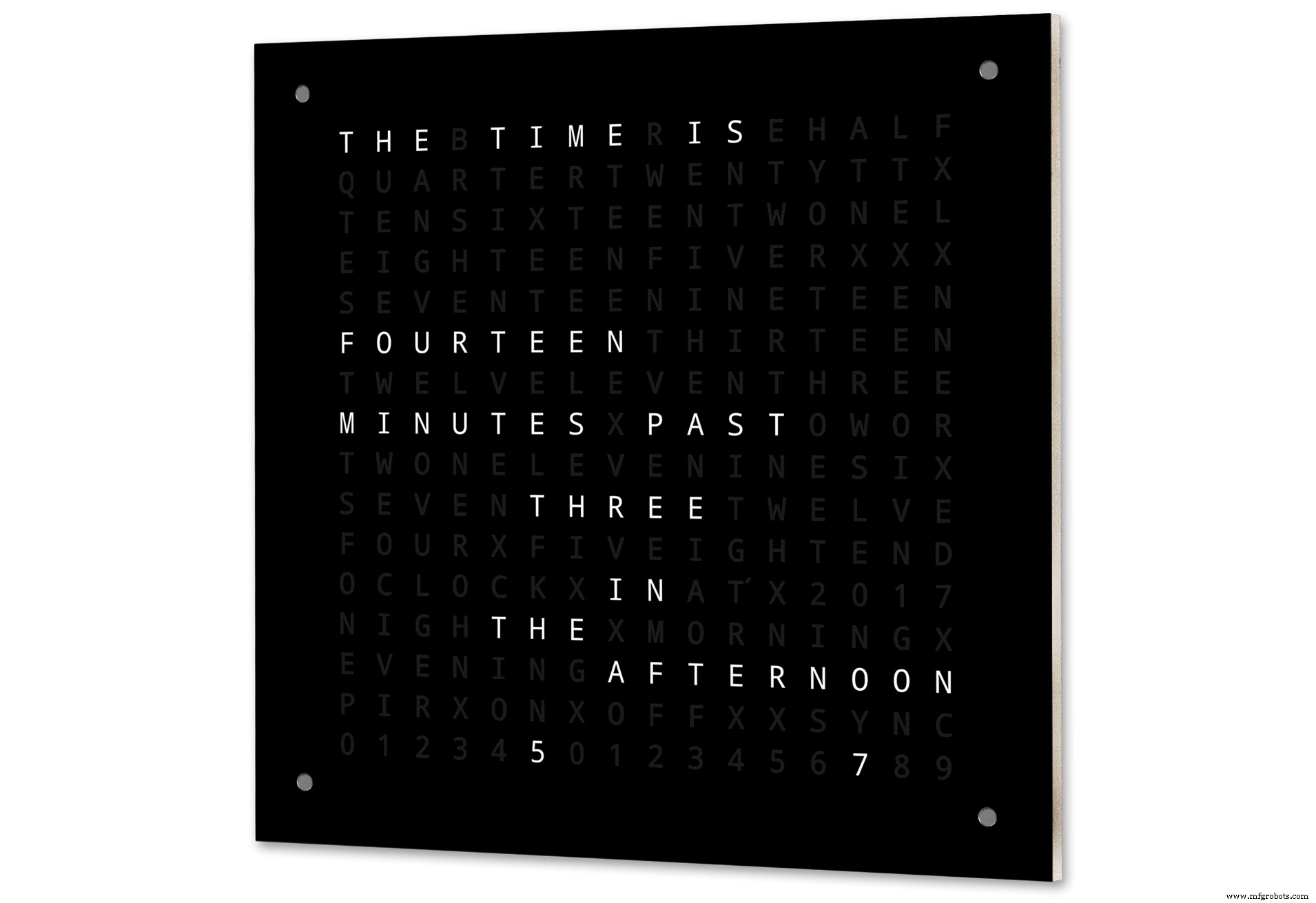
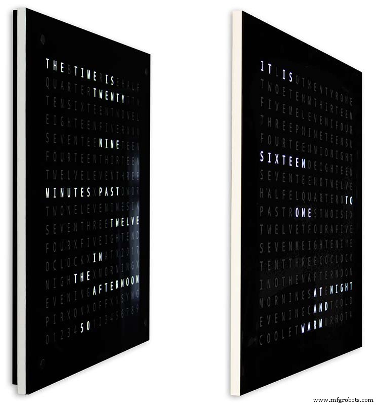
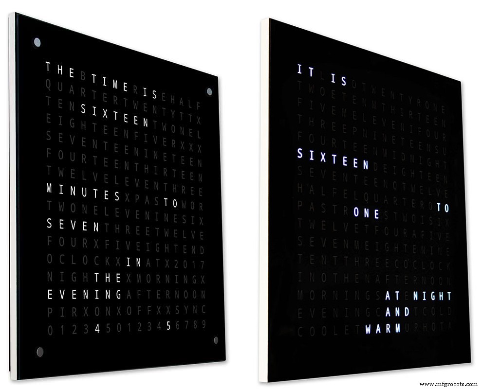
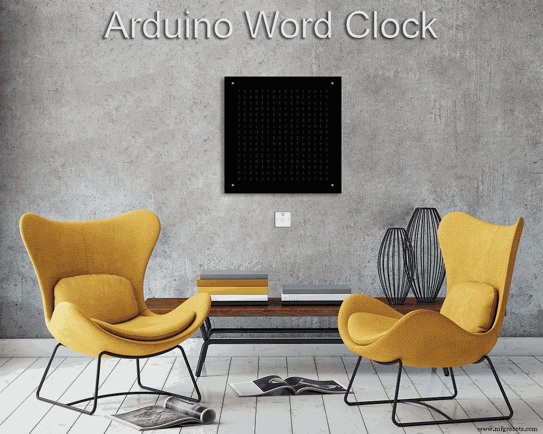
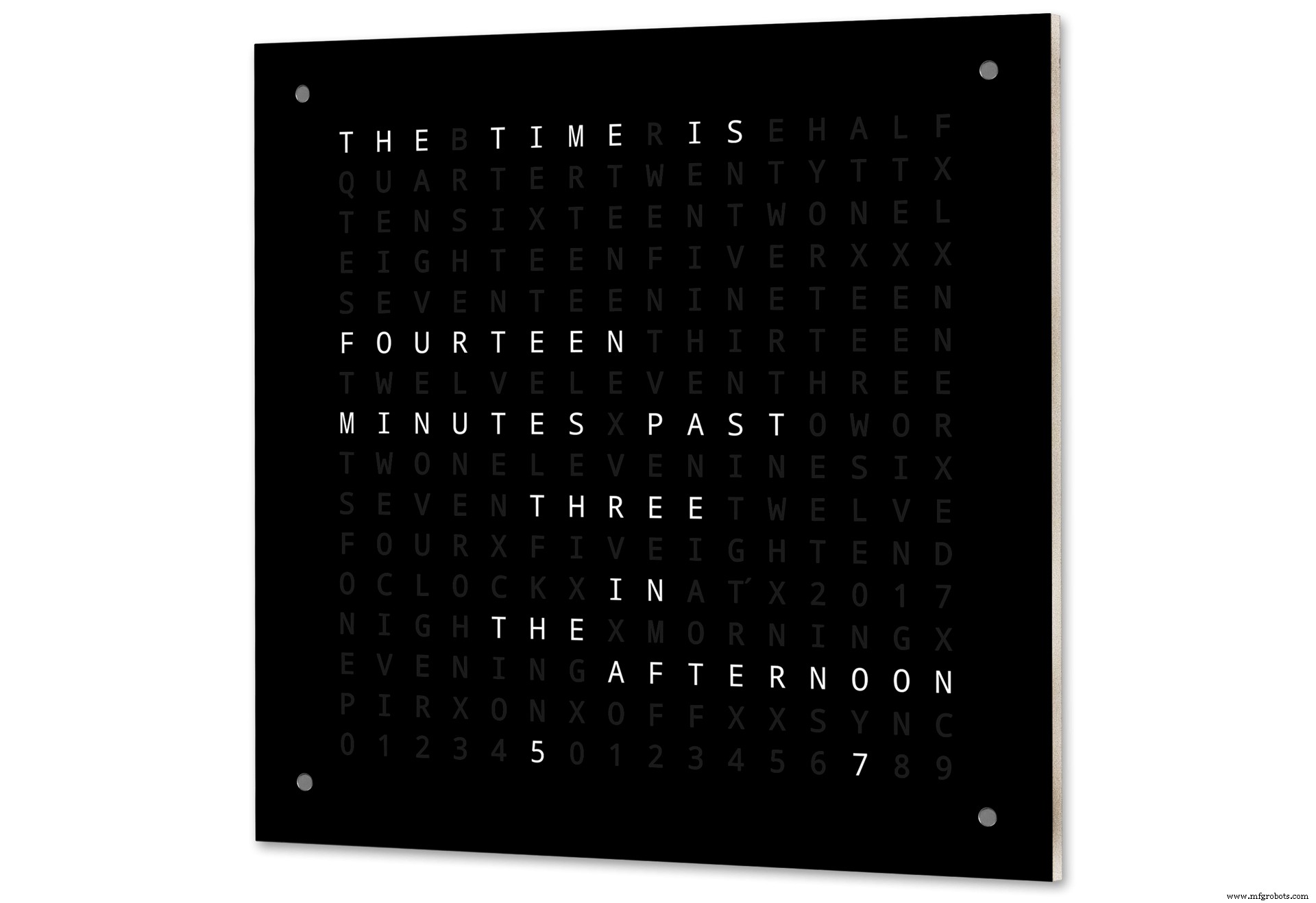
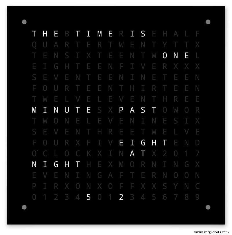
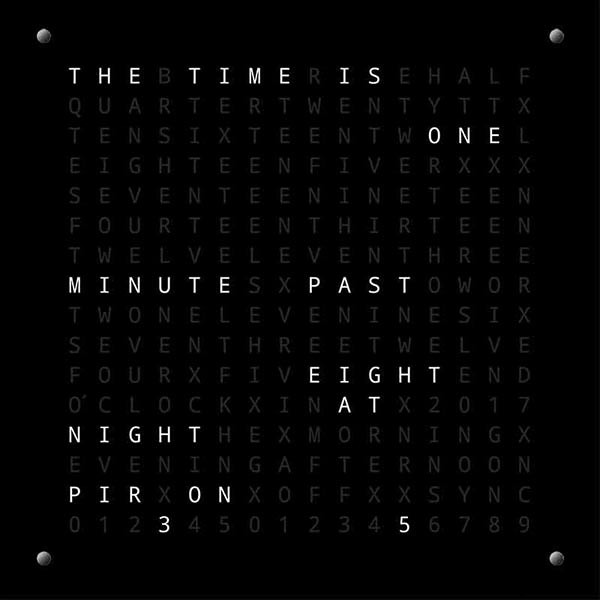
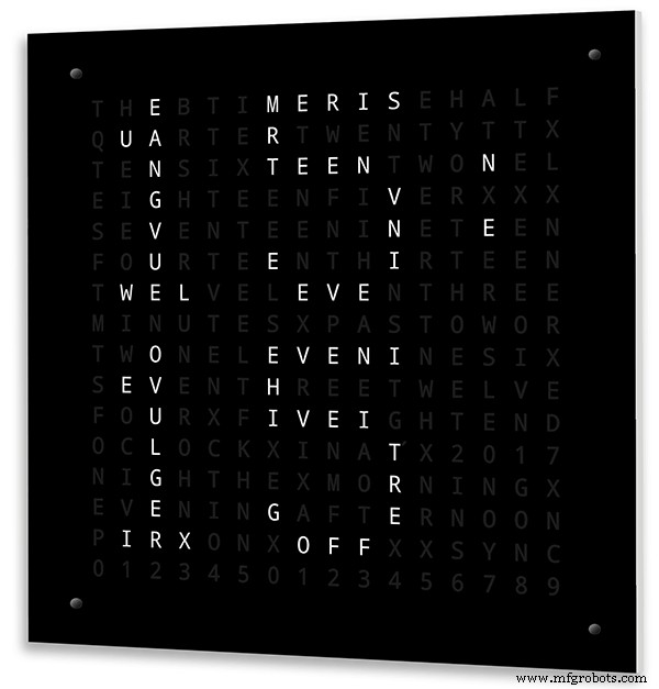
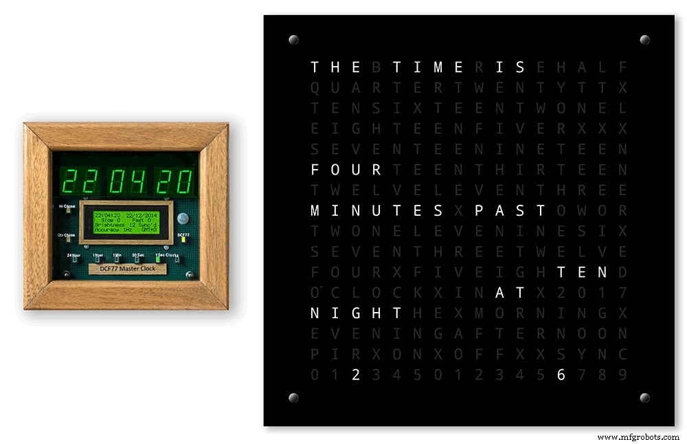
De Arduino-woordklok met minutenresolutie van tijd in woorden en lineaire weergave van seconden.
Er zijn ook modi voor digitale klok, analoge klok, temperatuur en vochtigheid, evenals drie spellen:Game of Life, Simon en Tetris.
De klok kan indien nodig standalone zijn of als een slave van een masterklok lopen.
Zonder een hoofdklok wordt de tijd geregeld door de ingebouwde temperatuurgecompenseerde real-cime klok van de wordclock.
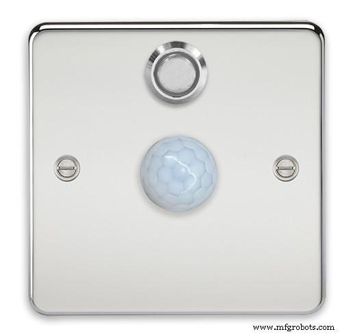
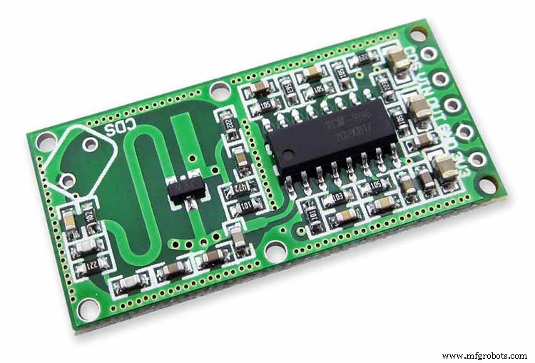
Er is een optie voor PIR- of Doppler-radarbesturing, zodat de klok automatisch wordt uitgeschakeld als er niemand in de kamer is.
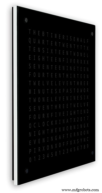
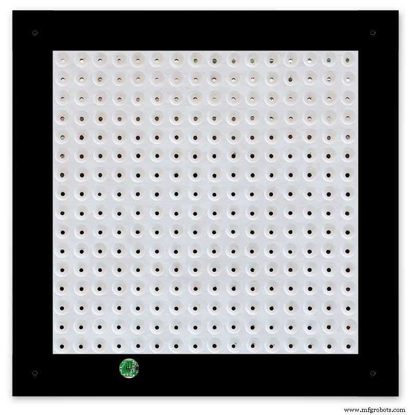
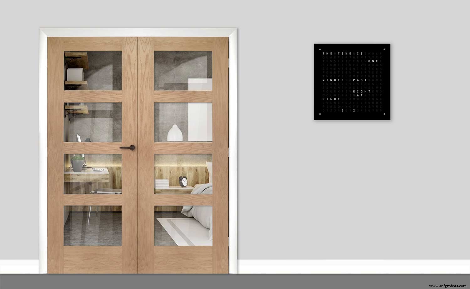
De klok meet 500 mm x 500 mm (19,68" x 19,68"), weegt 12 lb (5,5 kg) en is ontworpen om aan de muur te worden gemonteerd. Er zijn touchpads in elke hoek om de klok in te stellen en te bedienen.
Stap 1:Over Word Clocks
Over Word Clocks
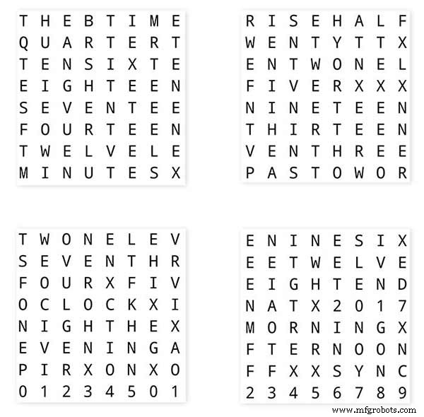
Woordklokken geven de tijd aan met behulp van een matrix van woorden of cijfers en letters en bestaan al vele jaren. Er zijn een paar verschillende ontwerptypes die de complexiteit van de klokbouw beïnvloeden.
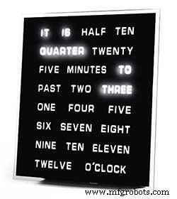
De eenvoudigste gebruiken woordblokken om de tijd aan te geven in een resolutie van vijf minuten, bijvoorbeeld O'CLOCK, 5 PAST, 10 PAST enz. Deze klokken gebruiken slechts ongeveer 20 individuele LED-blokken en zijn daarom het eenvoudigst te construeren. Het grootste nadeel van deze klokken is dat ze alleen de tijd in dit ingestelde formaat kunnen weergeven.
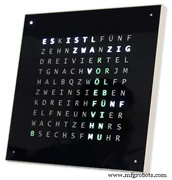
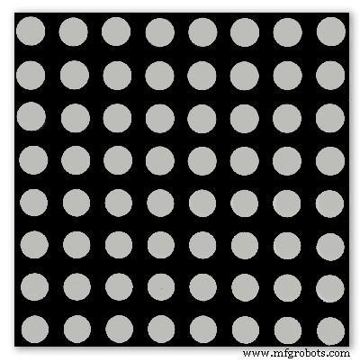
De klok met gemiddeld niveau heeft een 11x10 matrix van LED's plus vier extra LED's rond de buitenkant van de klok. De Raspberry Pi-gestuurde klok Photo 2 heeft zelfs meerkleurige LED's en omdat hij 110 individuele LED's heeft, kan hij cijfers en basisafbeeldingen weergeven. Deze klokken gebruiken nog steeds een resolutie van 5 minuten in woorden, maar voegen vaak "net 5 voorbij" of bijna 10 tot" toe om de resolutie iets te verhogen. Vaak geven de vier LED's rond de hoeken van het frame de voorbijgaande vier minuten aan om het gat tussen de resolutie van 5 minuten. Deze klokken zijn redelijk complex om te bouwen en gebruiken vaak strips van LED's om het bouwen te vergemakkelijken.
Er zijn commerciële versies van dit type klok beschikbaar. De 450 mm wandhangende versie kost ongeveer £ 1000 en heeft verwisselbare frontpanelen in vele kleuren en materialen, evenals kleinere desktops en horloges.
256 matrix Word Clock van Wouter Devinck
De woordklokken met het hoogste niveau van complexiteit gebruiken een 16x16 LED-matrix die een volledige 256 LED's geeft om te bedienen. Deze klokken hebben een resolutie van één minuut, evenals ochtend, avond, nacht enz. Ze vertellen vaak de ruwe temperatuur in woorden zoals warm, erg warm, koud erg koud etc.
Met de 256 LED's om mee te spelen zijn er enorme hoeveelheden verschillende weergavemodi beschikbaar. Deze klokken zijn vrij complex om te bouwen vanwege het aantal aansluitingen in het matrixdisplay. Het bouwen van de LED-matrix op PCB's met componenten voor opbouwmontage zorgt voor zeer slanke klokbehuizingen en maakt de displayconstructie eenvoudiger, maar boven 500 mm x 500 mm beginnen de PCB's duur te worden.
Handmatig bouwen van de LED-matrix zoals in mijn klok heeft ruimte nodig en 500 mm x 500 mm is een goed startpunt, omdat dit zo ongeveer de grote kabelbomen kan bevatten die nodig zijn om de LED's en displaymodules met elkaar te verbinden. Zeer grote wandvullende klokken kunnen worden gebouwd met behulp van met de hand gebouwde LED-matrices.
Stap 2:Wijzigingen
Wijzigingen
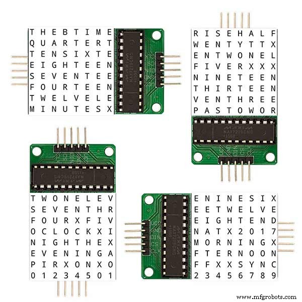
Deze klok is een mix van de Wouter Devinck Clock-hardware en de "Catalaanse" Pijuana-kloksoftware. Ik heb geen PCB's gebruikt, alleen kant-en-klare modules en drie kleine Vero-bordcircuits voor de stroomvoorziening.
De belangrijkste wijzigingen worden hieronder toegelicht.
Er worden geen aangepaste PCB's gebruikt in deze versie van de klok, gewoon goedkoop, gemakkelijk te verkrijgen door vooraf gebouwde modules.
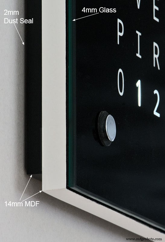
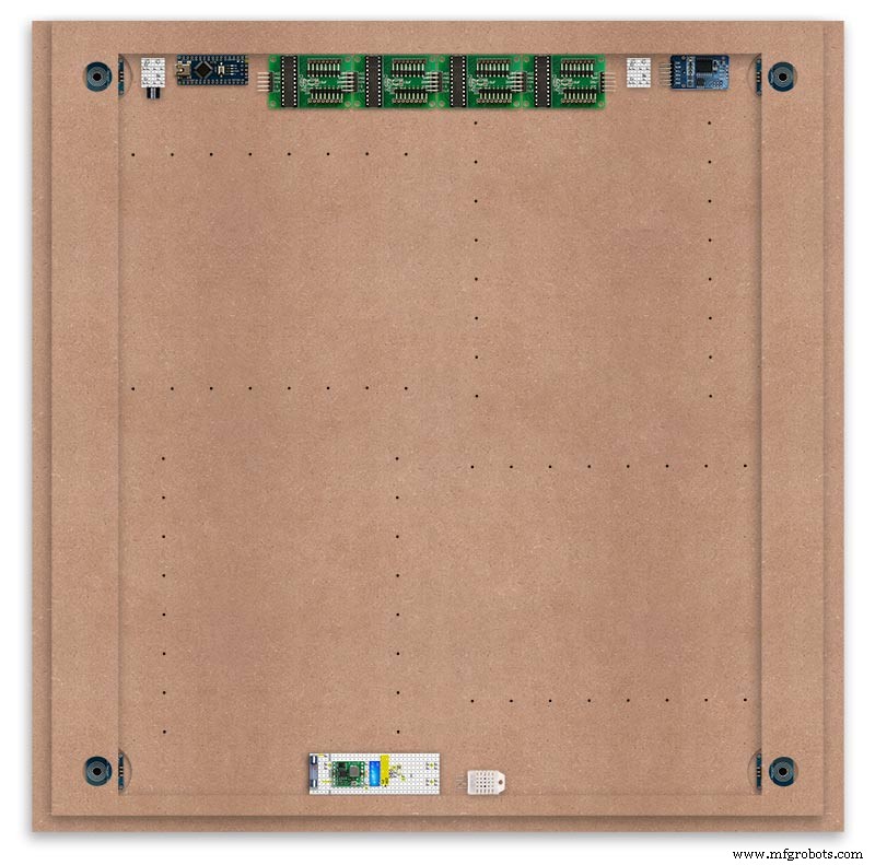
Het hoofdklokhuis is opgebouwd uit 2 x 14 mm MDF in plaats van een enkele 18 mm plaat.
Het achterblad is aan alle kanten 10 mm kleiner dan het voorblad, behalve aan de bovenkant, zodat de klok slechts 14 mm dik lijkt te zijn.
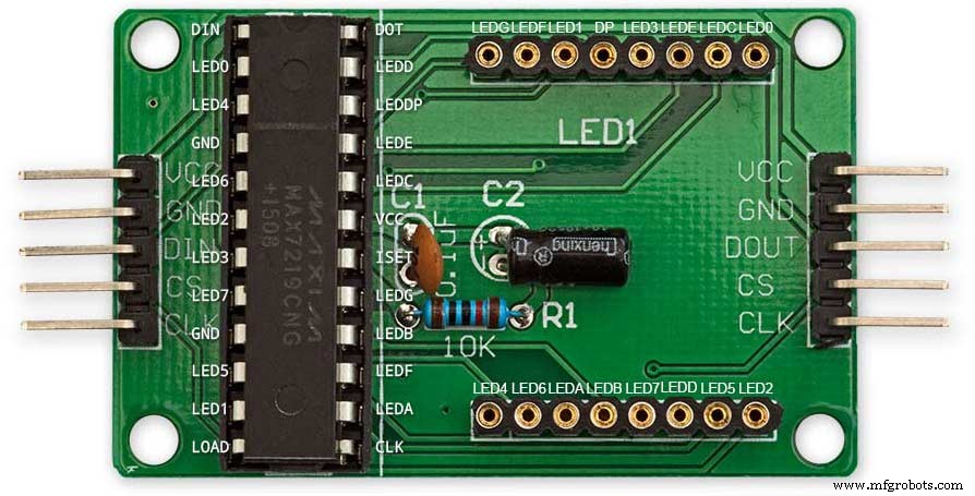
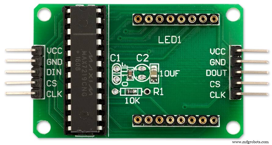
De klok van Wouter Devinck is slechts 20 mm diep inclusief het 2 mm glas, terwijl mijn klok eigenlijk 34 mm diep is inclusief het 4 mm glas en de 2 mm stofafdichting aan de achterkant. Door de terugslag van het achterste 14 mm paneel en de 1,5 mm terugslag van het glaspaneel vanuit de meeste hoeken lijkt de klok slechts 14 mm diep. Door deze extra diepte kon ik een met de hand gebouwde LED-matrix en kabelbomen gebruiken in plaats van 4 grote PCB's. Het betekent ook dat ik vooraf gebouwde onderhoudsvriendelijke modules kan gebruiken zonder IC's voor opbouwmontage op de MAX7219-kaarten.
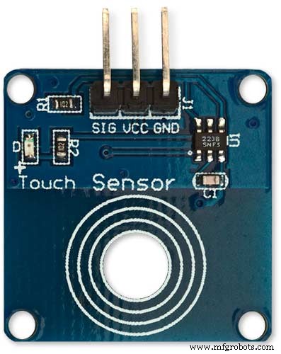
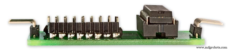
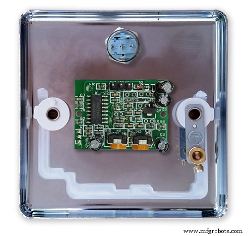
Het hoofddisplay is direct op de display-LED's gebouwd zonder PCB, dus elk formaat display is mogelijk. TTP223 aanraaksensormodules worden gebruikt in plaats van Azoteq IQS127D die op de hoofdborden is gemonteerd.
De beeldschermstuurprogrammakaarten voor de MAX7219 I/C gebruiken aangepaste LED-matrixkaarten. Deze borden worden compleet geleverd met alle componenten.
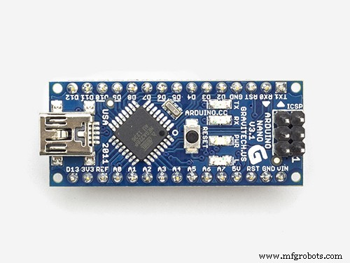
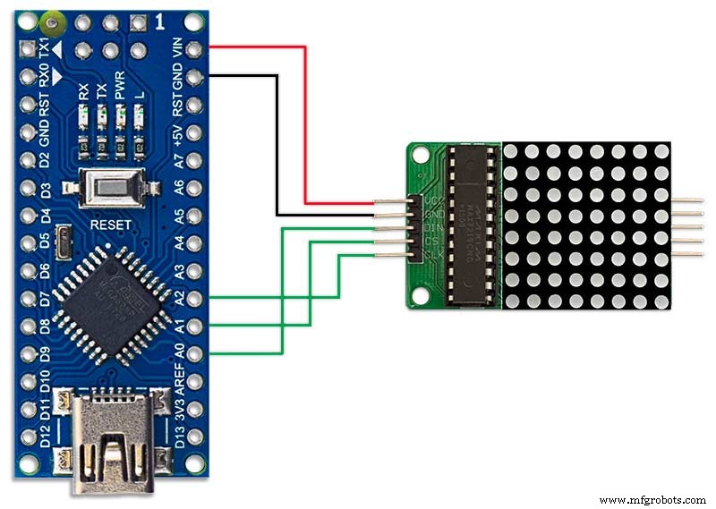
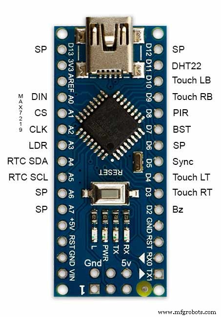
Vanwege zijn kleine formaat wordt een Arduino Nano gebruikt om de klok aan te sturen.
Een PIR-sensormodule wordt gebruikt om het display uit te schakelen wanneer er niemand in de kamer is (dit kan worden uitgeschakeld om het display altijd aan te houden).
Een trimmerweerstand is toegevoegd aan het circuit, toegankelijk vanaf de onderkant van de klok met een kleine platte schroevendraaier om de automatische helderheid van het display te kalibreren.
Synchronisatie met mijn hoofdkloksysteem elke minuut op 30 seconden. Als er geen synchronisatiepuls beschikbaar is, zal de klok vrijlopen met behulp van de RTC. Synchronisatiepulsen worden weergegeven op het hoofddisplay.
De software is voornamelijk gebaseerd op de "Catalaanse" Pijuana-versie van het woord klok, dus dit is vertaald in het Engels voor de weergave. Creditsweergave gewijzigd ten opzichte van de "Catalaanse" Pijuana-versie om het huidige softwareversienummer, mijn naam en ook het bouwjaar weer te geven.
De aangegeven temperatuur is verwijderd uit de klokweergave en er is een lineaire secondenweergave toegevoegd aan de onderste rij van de woord-, digitale en analoge klokken.
Wanneer de PIR aan of uit wordt gezet, wordt "PIR ON" of "PIR OFF" een paar seconden weergegeven op het wordclock-display.
Deze klok maakt gebruik van een DS3231 AT24C32 I2C Precision Real Time Clock Module volgens de Wouter Devinck Clock &de "Catalaanse" Pijuana-klok. Ik ben niet happig op het gebruik van de oplaadbare lithium-ionbatterij die bij de module wordt geleverd. Ik gebruik een niet-oplaadbare batterij en heb de module aangepast.
4 mm floatglas met gepolijste randen vervangt het 2 mm glas. Het glas wordt op de MDF-hoofdplaat bevestigd met Chicago Fasteners in plaats van lijm. Deze fungeren ook als touchpads om de klok te bedienen en zorgen ervoor dat het glas indien nodig kan worden verwijderd.
In de klok zijn twee stofafdichtingen ingebouwd, één op het achterpaneel en één achter het verwijderbare glazen displaypaneel. Als u in de klokinstellingsmodus op de BOT Right-knop drukt, worden de seconden nu teruggezet naar 0.
De volgende wijzigingen in de Engelse bewoording zijn aangebracht om de bewoording te maken zoals ik het zou zeggen. De manier waarop mensen zeggen dat de tijd is, verschilt van regio tot regio, afhankelijk van waar je woont/naar school ging, enz. Er is geen juiste manier die voor jou het beste klinkt.
De woorden die de temperatuur op de woordklok aangeven zijn verwijderd. Deze zijn vervangen door synchronisatiestatus, PIR AAN/UIT en lineaire weergave van seconden.
"MINUTEN" gewijzigd in "MINUTE" om 1 minuut over en 1 minuut voor het hele uur.
Een "A" toegevoegd voor het "QUARTER" verleden en "QUARTER" aan het uur.
De ontbrekende "ELEVEN" van Wouter Devinck-klok toegevoegd volgens zijn aantekeningen.
Om 12.00 uur veranderde de tijd om TWAALF UUR IN DE MIDDAG te lezen.
Om middernacht veranderde de tijd om TWAALF OCLOCK AT NIGHT te lezen. Na middernacht zegt de klok altijd IN DE OCHTEND.
De "O'CLOCK" is nu zonder interpunctie en toont alleen OCLOCK.
Stap 3:Case-ontwerp
Omdat mijn klok geen aangepaste Display Matrix-printplaten met componenten voor opbouwmontage gebruikt, moet mijn klokkast iets dieper zijn dan het ontwerp van Wouter.
Mijn koffer is 34 mm diep en bevat de achterste stofafdichting 2 mm, achterste MDF-plaat 14 mm, voorste displayplaat 14 mm en 4 mm floatglas.
Wouter's kast rechts is slechts 21 mm diep, 18 mm enkel MDF-paneel en 2 mm floatglas.
Om mijn klok er minder omvangrijk uit te laten zien wanneer hij aan de muur wordt gemonteerd, heb ik een paar eenvoudige ontwerpkenmerken opgenomen. Foto hierboven toont mijn klok aan de linkerkant en de klok van Wouter aan de rechterkant. Vanuit een extreem zijaanzicht kun je duidelijk zien dat mijn zaak er omvangrijker uitziet.
Dit wordt enigszins gecompenseerd doordat het achterste bord zwart is in plaats van wit, waardoor je oog zich concentreert op de slanke witte rand van 14 mm. Het achterbord is 10 mm korter aan de onderkant en beide zijden versterken deze illusie.
Boven - weer mijn klok links en Wouter's klok rechts. Hoe verder je naar de voorkant van de klok gaat, hoe korter de achterkant van mijn klok is, totdat alleen het slanke 14 mm-frontbord zichtbaar is. Het 4 mm-glas is ook 1-2 mm korter gesneden dan het voorbord, waardoor het aan het zicht wordt onttrokken . Mijn omvangrijke klokkast van 34 mm lijkt nu net zo dun als die van Wouter.
Stap 4:Bediening
Bediening

Er zijn TTP223 aanraakbedieningsmodules op de klok, linksboven, rechtsboven, linksonder en rechtsonder op het display.
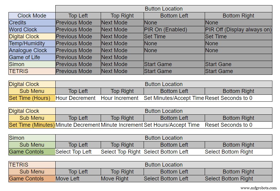
De knoppen hebben verschillende functies, afhankelijk van de modus waarin de klok zich bevindt, zie bovenstaande tabel.
Stap 5:Automatische zomer-winterinstelling
Niet gebruikt.
Stap 6:Weergavemodi Klokken en omgeving
Animatie 1 hierboven toont de 4 klok- en omgevingsmodi.
De modi zijn in volgorde woordklok, digitale klok, temperatuur en vochtigheid en analoge klok.
Animatie 2 hierboven. Er is ook een opstartmodus die door het softwareversienummer, de naam van de maker en de naam van de klok bladert.
Stap 7:Weergavemodi Games
Drie klassieke spellen zijn gecodeerd in de klok. Ik heb de code van de Catalaanse klok gelaten zoals deze is.

Animatie 1 boven Conway's Game of Life. Het universum van het Game of Life is een oneindig tweedimensionaal orthogonaal raster van vierkante cellen, die zich elk in een van de twee mogelijke toestanden bevinden, levend of dood, of "bevolkt" of "onbevolkt".
Elke cel staat in wisselwerking met zijn acht buren, dit zijn de cellen die horizontaal, verticaal of diagonaal aangrenzend zijn. Bij elke stap in de tijd vinden de volgende overgangen plaats:Elke levende cel met minder dan twee levende buren sterft, alsof ze veroorzaakt zijn door onderbevolking. Elke levende cel met twee of drie levende buren leeft voort op de volgende generatie. Elke levende cel met meer dan drie levende buren sterft, als door overbevolking. Elke dode cel met precies drie levende buren wordt een levende cel, als door reproductie.
Het initiële patroon vormt de kiem van het systeem. De eerste generatie wordt gecreëerd door de bovenstaande regels gelijktijdig toe te passen op elke cel in het zaad. Geboorten en sterfgevallen vinden gelijktijdig plaats, en het discrete moment waarop dit gebeurt wordt soms een teek genoemd (met andere woorden, elke generatie is een pure functie van de voorgaande generatie). een). De regels worden herhaaldelijk toegepast om nieuwe generaties te creëren.
Animatie 2 boven Simon
Simon-geheugenspel - probeer de door de computer gegenereerde reeks en kopieer de door de computer gegenereerde reeks. Dubbeltik bij het invoeren van uw reeks op de laatste invoer om uw beurt te beëindigen.
Als je faalt, wordt je score op het scherm weergegeven.
Animatie 3 hierboven TetrisTetris is het Sovjet-puzzelspel voor het matchen van tegels dat in juni 1984 werd uitgebracht. Dit spel heeft nog wat werk aan de knoppen nodig om de tegels correct te besturen.
Stap 8:Prototyping
De klok kan worden geprototypeerd en getest met behulp van de originele DOT Matrix-LED's op de MAX7219-displayborden.
Let op:deze tijdelijke wijziging is alleen vereist als u uw code wilt testen op de DOT-matrixschermen die bij de MAX7219-modules worden geleverd.
Dit betekent dat u uw software-/woordlay-outaanpassingen in het klein kunt uitproberen voordat u zich vastlegt op de volledige versie. De bedrading naar de DOT Matrix LED zal moeten worden aangepast om overeen te komen met de software-aansluitingen.
De bovenstaande afbeelding laat zien hoe de module is bedraad voordat deze wordt gewijzigd. De wijziging is vrij rechttoe rechtaan. Buig eerst de volgende LED Matrix-pinnen 90°, de bovenste pinnen omhoog en de onderste pinnen naar beneden.
Pinnen 16, 15, 3, 4, 10 &11.
Steek de LED Matrix in de bus op de displayprint, de bovenstaande pinnen worden nu niet aangesloten. Soldeer de volgende verbindingsdraden van de achterkant van de socket van de display-PCB naar de LED Matrix-pinnen die uitsteken.
LEDA naar Dot Matrix Pin 16
LEDB naar Dot Matrix Pin 15
LEDG naar Dot Matrix Pin 3
LEDF naar Dot Matrix Pin 4
LEDE naar Dot Matrix Pin 10
LEDC naar Dot Matrix Pin 11
Ik gebruikte een multimeter en zoemde uit de display-module. De tabel laat zien waar het software-pinnummer verschilt van de LED-pinnummers op het displaybord.
Om uw woordlay-outs te testen, drukt u een miniatuurversie van uw woordweergave 62 mm x 62 mm af op gewoon wit papier.
Let op de richting van de LED-displayborden zodat deze overeenkomt met de softwarelay-out.
Ik heb de schermrotatie behouden als de originele Wouter Devinck-klok voor het geval iemand het PCB-ontwerp van Wouter Devinck voor mijn klok gebruikt.
De kleine drukknop onder de temperatuur/vochtigheidssensor wordt gebruikt om de 30 seconden synchronisatie te testen. De aanraakknopmodules bevinden zich linksonder op het breadboard zijwaarts gemonteerd. Er zijn niet veel draden op dit prototype, omdat de meeste bedrading zich in de displaymatrixen bevindt. Op de laatste klok wordt deze bedrading met de hand gedaan naar de individuele LED's.
Ik heb veel verschillende woord-/klokontwerpen op dit bord uitgeprobeerd voordat ik probeerde de laatste klok te bouwen.
Stap 9:De aangepaste modules testen
Ik heb de wordclock-schets aangepast zodat de MAX2719-module kan worden getest na de bedradingsmod.
Dit programma verlicht elke LED beurtelings van linksboven naar rechtsonder in de matrix.
Sluit gewoon 5 draden aan op de NANO- en MAX2719-module en voed de NANO via de USB-poort. Laad de schets en laat hem lopen.
Sluit elke module om de beurt aan om uw bedrading te controleren.
Download de testschets uit het bijgevoegde zipbestand.
MAX7219_LED_Test.zip
Stap 10:Tijd tot woordtoewijzing
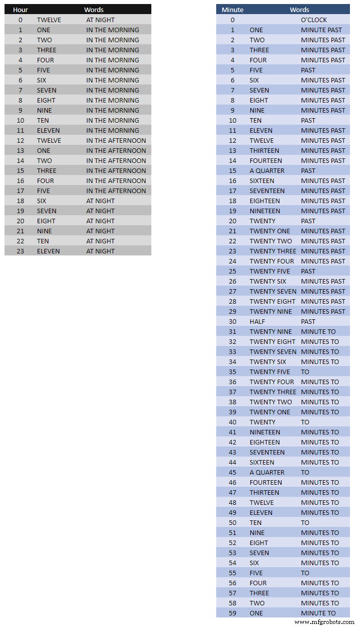
De bovenstaande tabel toont de tijd-tot-woord-toewijzingen.
Er zijn geen vaste regels voor deze, stel gewoon de woorden in zoals je de tijd zou vertellen.
In mijn klok heb ik het volgende veranderd ten opzichte van de woorden op de klok van Wouter.
"MINUTEN" veranderde in "MINUTE" om 1 minuut over en 1 minuut voor het uur. Een "A" toegevoegd voor het "QUARTER" verleden en "QUARTER" aan het uur.
Om 12.00 uur veranderde de tijd om TWAALF UUR IN DE MIDDAG te lezen.
Om middernacht veranderde de tijd om TWAALF OCLOCK BIJ NACHT te lezen.
Na middernacht zegt de klok altijd IN DE OCHTEND.
Deze wijzigingen zijn zeer eenvoudig te implementeren in de kloksoftware.
Word%2Bto%2BTime%2BTranslations.xlsx
Stap 11:Stroom
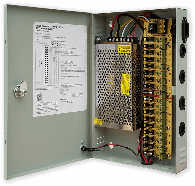
Ik gebruik een gewone 12 volt voedingseenheid om veel verschillende soorten circuits door mijn huis te sturen. Deze 12 volt-voeding wordt vervolgens lokaal op elk circuit afgebouwd met een 5 volt-module om de besturingskaart en verschillende modules van stroom te voorzien.
Mijn gemeenschappelijke voeding heeft 18 individueel gezekerde 12v-circuits met elk een zekering van 2A. 9 hiervan hebben een back-up van de batterij. Klokborden hebben ook hun eigen ingebouwde zekering.
Als u slechts dit ene circuit gebruikt, zal elke gereguleerde 5 volt-voeding het doen zolang deze de stroom kan leveren voor uw circuitgebruik.
Ik heb een power board ontworpen op Vero die gebruik maakt van een MP1584 miniatuur voeding. Dit converteert de 12v-uitgang van mijn gewone voeding naar de 5v voor de klok.
Er zijn twee extra powerboards gemaakt van Vero board.
Afgezien van 1 die de zoemer vasthoudt, voegen ze gewoon extra stroomdistributiepunten toe voor de stroombedrading van de klok.
Stroomvereisten
Ik heb de stroomafname van de klok gemeten en bij lage helderheid gebruikt deze 30mA en volledige helderheid 250mA. Dit is natuurlijk afhankelijk van het aantal LED's dat brandt. Op een zonnige dag zijn de helderheidsniveaus die op de seriële uitgang worden aangegeven 10. Dit is ongeveer 2 derde van het maximale vermogen van de LED's. Het totale stroomverbruik kan aanzienlijk worden verminderd als de PIR is ingeschakeld. Hierdoor wordt het display leeggemaakt als er geen beweging wordt gedetecteerd door de klok.
Ik zou een voeding van minimaal 500mA gebruiken om de klok van stroom te voorzien. Het vermogen is sterk afhankelijk van het type LED's dat u gebruikt.
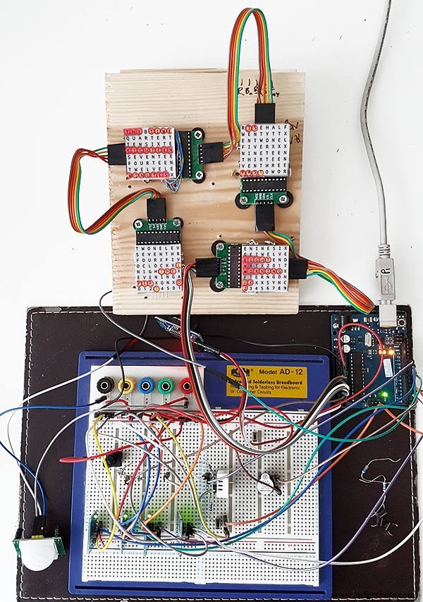
Stap 12:Module-interconnecties
Foto hierboven laat zien hoe de modules zijn aangesloten. De meeste modules maken rechtstreeks verbinding met de Arduino Nano.
De MAX7219-kaarten maken alleen verbinding met de NANO via module 01. De andere modules zijn in serie aan elkaar geschakeld.
Elke 8x8 LED-matrix wordt vervolgens aangesloten op een MAX7219-module.
Het grootste deel van de bedrading zijn de verbindingen tussen de MAX7219-modules en de LED-matrixen.
Houd de afstand tussen de NANO en de 1e MAX7219-module en MAX7219-module tot modules zo kort mogelijk. Zorg er ook voor dat u beide uiteinden van de in serie geschakelde MAX7219's van stroom voorziet, aangezien de meeste stroom door dit deel van het circuit wordt getrokken.
Stap 13:Bouwvolgorde van bouwen
Volgorde van build, ervan uitgaande dat alle prototyping en softwarewijzigingen als eerste zijn voltooid.
Laat vinyl transfer printen.
Laat het glas snijden.
Snijd MDF-platen voor en achter.
Snijd gaten in het voorblad voor LED's.
Verf MDF-platen.
Snijd gaten voor sensoren in glas.
Plak vinyltransfer op de achterkant van het glas.
Snijd sensorgaten in de MDF-frontplaat.
Snijd de sponningen van de sensormodule in het voorpaneel.
Snijd de MDF-achterplaat en maak 4 toegangsgaten voor toegang tot de sensor.
Voeg melamine randstroken toe aan MDF-platen, wit aan voorplaat en zwart aan achterplaat.
Schroef de MDF-plaat terug op de MDF-plaat aan de voorkant.
Maak Vero-kaarten, 1 voedingskaart en 2 stroomverdeelborden.
Wijzig 4 x MAX7219-kaarten en voeg bedrading toe aan LED's.
Sluit voorlopig alleen aan op MAX7219.
Monteer alle modules en Vero-platen op de achterkant van de MDF-frontplaat.
Construeer alle 4 LED-matrices op de MDF-plaat aan de voorkant en soldeer 256 LED's.
Sluit alle Batt- en Earth-kabels aan vanaf het Vero-bord van de voeding en de stroomverdeelborden.
Sluit alle stroomlijnen aan op alle modules.
Sluit alle bedrading aan op Nano, MAX7219-modules, RTC, temperatuursensor, aanraaksensoren en zoemer.
Sluit alle kabelbomen van gemodificeerde MAX7219-kaarten aan op LED-matrixen volgens de bedradingstabel.
Sluit een PIR-module op afstand vanaf de klok aan en sluit de PIR-verbinding aan.
Sluit de 30 seconden synchronisatie aan op uw Master Clock (indien nodig).
Monteer het glazen frontdisplay met behulp van de Chicago-bouten waarmee tegelijkertijd de aanraaksensoren worden bevestigd.
Testen.
Tabel 1 toont de zeer geschatte bouwtijden voor deze klok en zal variëren afhankelijk van uw vaardigheidsniveau en ook eventuele specialistische gereedschappen/werkruimte die u bij de hand hebt.
Je kunt gemakkelijk nog eens 40 uur prototyping en programmeertijd aan die lijst toevoegen.
Stap 14:Constructie Vinylsticker
Vinylsticker
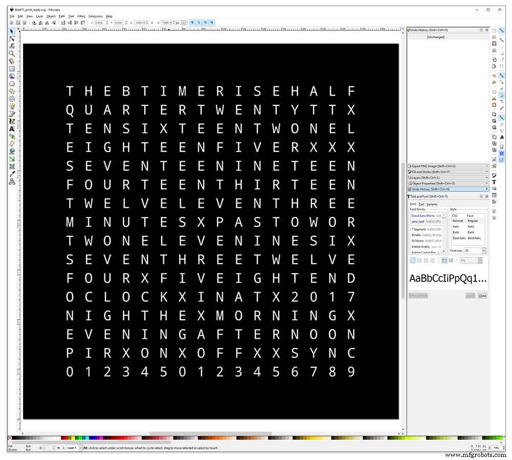
De vinylsticker is ontworpen in Inkscape.
Inkscape is vector grafische software van professionele kwaliteit die draait op Windows, Mac OS X en GNU/Linux. Het wordt gebruikt door ontwerpprofessionals en hobbyisten over de hele wereld voor het maken van een breed scala aan afbeeldingen, zoals illustraties, pictogrammen, logo's, diagrammen, kaarten en webafbeeldingen.
Inkscape gebruikt de W3C open standaard SVG (Scalable Vector Graphics) als zijn eigen formaat en is gratis en open-source software.
Ik heb het originele Inkscape-ontwerp van Wouter Devinck uit zijn GitHub-repository gedownload en het vervolgens in Inkscape aangepast aan mijn ontwerp. Ik heb veel verschillende versies uitgeprobeerd op mijn miniatuurprototype voordat ik het definitieve ontwerp opstuurde om te worden afgedrukt.
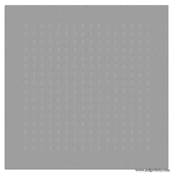
Vergeet niet de sticker omgekeerd te laten bedrukken!
Ik gebruikte een bedrijf genaamd Regal Signs &Graphics dat mijn sticker in zwart vinyl leverde, omgekeerd gesneden, belettering verwijderd en geleverd met een applicatietape, allemaal voor ongeveer £ 27 inclusief btw.
Hoewel ze vrij lokaal voor mij zijn, heb ik wat meer betaald en mijn sticker in een mooie veilige kartonnen koker afgeleverd.
Ik had een paar problemen om het ontwerp in het juiste formaat voor hun machine te krijgen, maar uiteindelijk heb ik het vanuit Illustrator in eps-formaat verzonden. De zeer behulpzame mensen van Regal Signs hebben het verkleind tot het juiste formaat voor mij. Mijn Inkscape-bestand kan worden gedownload hier VINYL STICKER.
De vinylsticker kwam van Regal Signs met de letters eruit gehaald, dus dit bespaarde me veel tijd. De sticker wordt geleverd met een plastic tape over de voorkant (glas) en een applicatiepapier op de achterkant. Meestal pel je de tape aan de zijkant af, breng je de sticker aan en verwijder je het applicatiepapier. Ik besloot het applicatiepapier erop te laten zitten omdat het als diffusor voor de LED's fungeerde. Terwijl ik het applicatiepapier erop liet zitten, knipte ik het overtollige papier rond de sticker af voordat ik het aanbracht.
Het aanbrengen van de sticker was relatief eenvoudig. Zorg ervoor dat je een paar YouTube-video's bekijkt op de vinylsticker-applicatie op glas voordat je het zelf probeert.
Glas

De klok maakt gebruik van 4 mm floatglas en is gesneden tot precies 500 mm x 500 mm. Omdat de randen zichtbaar zijn, zijn de randen ook gepolijst. Dit is allemaal gedaan door mijn plaatselijke glaszetters voor £ 20.
Vervolgens werden gaten van 5 mm in het glaspaneel geboord met behulp van een glasboor van 5 mm. Bekijk YouTube-video's over het boren van gaten in glas.
Ik heb het glas eerst schoongemaakt met aceton en ervoor gezorgd dat het stofvrij was (heel belangrijk). Ik deed toen wat plastic handschoenen aan om er zeker van te zijn dat ik geen vingerafdrukken op de sticker kreeg.
Ik heb het glas besproeid met een zeer verdund mengsel van zeep en water en toen heel langzaam de plastic film van de sticker verwijderd om het vooroppervlak te onthullen.
Het is belangrijk om de folie langzaam en in een zeer scherpe hoek los te trekken, zodat de letters op de sticker op het transferpapier blijven zitten. Zodra de sticker volledig is blootgesteld, brengt u deze aan op het natte glasoppervlak.
Door het water/zeep mengsel kun je de sticker naar de juiste plek op het glas verplaatsen. Gebruik vervolgens een creditcard en werk weg van het midden van de sticker om eventuele luchtbellen te verwijderen. Laat de sticker een nacht drogen en knip dan vanaf de achterkant van de sticker het vinyl over de 4 montagegaten in het glas weg.
Brett11_print_ready.svg
Stap 15:constructie moederborden deel 1
Hoofdborden
Het moederbord van de klok bestaat uit 2 vellen 14 mm MDF. Het achterblad is 10 mm kleiner dan het bovenblad aan alle kanten behalve de bovenkant. De bovenkant heeft witte randen terwijl de achterkant zwarte randen heeft. Als je hem aan de muur bekijkt, lijkt de klok 14 mm diep te zijn.
Het moederbord van de klok bestaat uit 2 vellen 14 mm MDF. Het achterblad is 10 mm kleiner dan het bovenblad aan alle kanten behalve de bovenkant. De bovenkant heeft witte randen terwijl de achterkant zwarte randen heeft. Als je de klok aan de muur bekijkt, lijkt hij 14 mm diep te zijn.
Op de originele Wouter Devinck Clock &de "Catalaanse" Pijuana-versie wordt een enkele 18 mm dikke plaat MDF gebruikt met de achterkant naar buiten om ruimte te maken voor de PCB en componenten. Door 2 vellen MDF te gebruiken, kan het bord eenvoudig worden uitgesneden met een decoupeerzaag in plaats van het tijdrovende en stoffige frezen. Het bovenblad is 503 mm x 503 mm om een overlapping van 1,5 mm rond het glas te geven. Dit geeft het glas een beetje bescherming tegen stoten.
Het bord is uitgesneden met een decoupeerzaag en biedt 14 mm ruimte aan componenten.
De diepste PCB inclusief componenten zijn de MAX 7219-modules die 10 mm diep zijn. Na voltooiing wordt de achterplaat op de voorplaat gelijmd of geschroefd.
Constructie voorbord
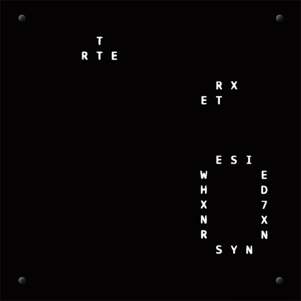
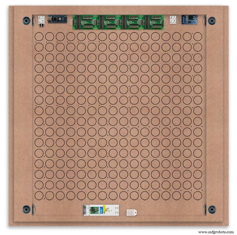
Het frontbord bevat de 256 LED's die door gaten van 6,5 mm en bredere 18 mm verzonken gaten schijnen om individuele letters en cijfers op het display te verlichten.
Het bord is gemarkeerd om de boorpositie in het midden van elk weergavekarakter weer te geven. Met behulp van een display van 500 mm heb ik mijn vinylplaat gemeten en de tekens staan 25 mm uit elkaar vanaf 62,5 mm vanaf de randen. Ik heb deze lijnen op de MDF getekend, de snijpunten zijn de boorpunten.
Ik gebruikte de bovenrand als het referentiepunt dat ik heb gemeten en markeerde elke rij vanaf dit punt.
Dit werd herhaald voor de verticale kolom met de linkerrand als referentiepunt.
De snijpunten van het raster vormen het middelpunt voor de 6 mm LED-montagegaten en de 18 mm verzonken gaten.
Using an automatic centre punch ( use a nail or screw if you don't have one) I punched the 256 intersection points of the grid.
Using a drill bit to suite your LEDs (6mm in my case) and using the punched holes as a guide for the drill bit drill out all 256 LED mounting holes.
The next task is to drill the 256 18mm countersunk holes using a 20mm countersinking bit.
To keep the countersunk holes at a uniform depth and width I built a countersinking jig using an off cut of wood. To make the jig a hole is drilled in the wood off cut to just fit the silver rotating bezel of my drill chuck. Using a test piece of MDF the countersinking bit is then moved in and out of the chuck until a countersunk hole of the correct diameter is made when drilling through the hole upto the chuck in the off cut of wood. Once the correct distance is found the chuck is tightened and the main board is drilled 256 times by centring the hole in the wood over the existing 6mm holes then drilling down until the chuck bezel hits the hole in the countersinking jig.
Completed front board with 256 countersunk holes and 6mm holes for the LEDs.
The board is then rubbed down and primed using MDF primer and painted white so the countersunk holes reflect the light from the LEDs.
A black edge is painted around the outside edge to hide the board as the glass is 1mm shorter all round. This setback also helps the glass disappear from view on the final clock.
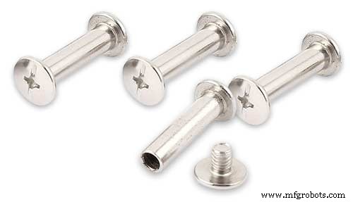
Four 5mm holes are then drilled in the corners to take the Chicago Fasteners. The Chicago Fasteners hold the glass in place, hold the touch sensors and provide a touch sensitive pad on top of the glass. The fasteners have 3mm shafts and will have a small bit of rubber tape wrapped around the shafts to protect the glass.
Turn the board over and drill a rebate with a forstner bit to take the four touch sensors. This hole will be offset from the hole drilled in the previous step.
Wall Mounts
The clock is fixed to the wall by two metal picture hanging mounts.
These are recessed into the frame so the highest point of the bracket is level with the frame.
Two 2" countersunk No6 screws sit in these bracket and hold the clock to the wall with a bit of tension so the dust seal is compressed.
Step 16:Construction Touch Sensor Mounting
The touch sensor modules are fixed to the front panel using the Chicago Fastener bolts. The Chicago Fastener bolts then act as touch sensors.
A 5mm hole is drilled through the sensor pad on the module to allow the Chicago Fastener bolt to pass through.
The sensor pad is insulated by the MDF panel and a plastic washer.
The touch pad on the sensor module has a 5mm mounting hole drill through the sensor.

Touch sensors in rebates behind rear panel. Holes drilled into rear panel allows access to the Chicago Fasteners that hold the sensors/glass front in place.
Clock front panel with four Chicago Fastener tops acting as touch plates.
Step 17:Electronic Components &Modules
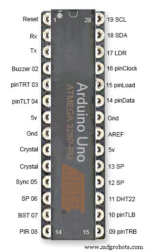
ATmega328 pin connections in case you want to prototype the circuit on an Arduino Uno. Note BST pin 07 is not used.
Pin label numbers refer to Arduino IDE numbers.
LEDs
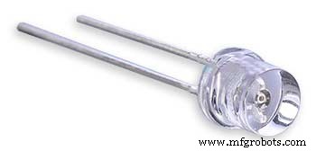
Make sure you purchase your LEDs from a good source. These LEDs will be on for many hours a day. I have has problems with LEDs failing after a few weeks use.
My LEDs Specs
5mm White Flat Top LEDs offering a pure and consistent colour with a wide angle ultra bright light output.
Colour :White
Quantity :256
Lenses Type :Round Flat Top
Crystal ClearBrightness :13000mcdForward
Voltage :3.2v - 3.8v
Forward Current :20mA (typical), 30mA (Max)
Viewing Angle :120 degrees
DHT22 Temperature &Humidity Sensor
The DHT22 is a basic, low-cost digital temperature and humidity sensor. It uses a capacitive humidity sensor and a thermistor to measure the surrounding air, and sends out a digital signal on the data pin.
You can only get new data from it once every 2 seconds, so sensor readings can be up to 2 seconds old.
Simply connect the first pin on the left to 3-5V power, the second pin to your data input pin and the right most pin to ground.
To prevent the temperature of the inside clock case being measured the top and left side vent of the DH22 are covered over with tape. This also stops dust being drawn into the clock case.
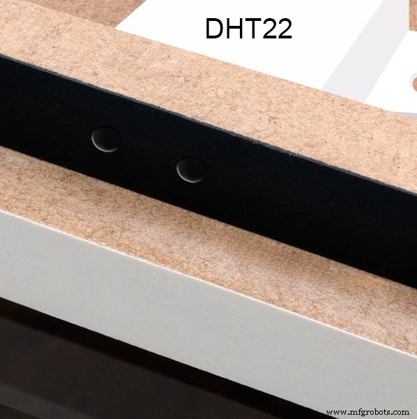
The DHT22 is mounted with its right open side mounted tight against the lower rear cover.Two small holes are drilled in the lower edge of the rear MDF board to allow air from the room to circulate around the sensor.
Arduino NANO
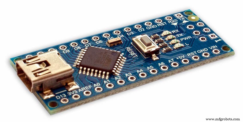
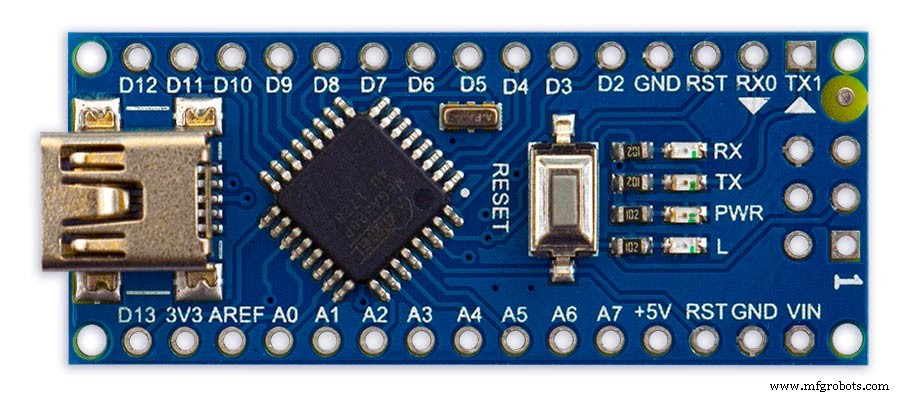
PowerThe Arduino Nano can be powered via the Mini-B USB connection, 6-20V unregulated external power supply (pin 30), or 5V regulated external power supply (pin 27). The power source is automatically selected to the highest voltage source.
Memory
The ATmega328 has 32 KB, (also with 2 KB used for the bootloader.
The ATmega328 has 2 KB of SRAM and 1 KB of EEPROM.
Input and Output
Each of the 14 digital pins on the Nano can be used as an input or output, using pinMode(), digitalWrite(), and digitalRead() functions. They operate at 5 volts. Each pin can provide or receive a maximum of 40 mA and has an internal pull-up resistor (disconnected by default) of 20-50 kOhms. In addition, some pins have specialized functions:Serial:0 (RX) and 1 (TX). Used to receive (RX) and transmit (TX) TTL serial data. These pins are connected to the corresponding pins of the FTDI USB-to-TTL Serial chip.
External Interrupts:2 and 3.
These pins can be configured to trigger an interrupt on a low value, a rising or falling edge, or a change in value. See the attachInterrupt() function for details.
PWM:3, 5, 6, 9, 10, and 11. Provide 8-bit PWM output with the analogWrite() function.
SPI:10 (SS), 11 (MOSI), 12 (MISO), 13 (SCK). These pins support SPI communication, which, although provided by the underlying hardware, is not currently included in the Arduino language.
LED:13. There is a built-in LED connected to digital pin 13. When the pin is HIGH value, the LED is on, when the pin is LOW, it's off.
The Nano has 8 analog inputs, each of which provide 10 bits of resolution (i.e. 1024 different values). By default they measure from ground to 5 volts, though is it possible to change the upper end of their range using the analogReference() function. Analog pins 6 and 7 cannot be used as digital pins. Additionally, some pins have specialized functionality:I2C:4 (SDA) and 5 (SCL). Support I2C (TWI) communication using the Wire library (documentation on the Wiring website).
There are a couple of other pins on the board:AREF. Reference voltage for the analog inputs. Used with analogReference(). Reset. Bring this line LOW to reset the microcontroller. Typically used to add a reset button to shields which block the one on the board.
Communication The Arduino Nano has a number of facilities for communicating with a computer, another Arduino, or other microcontrollers. The ATmega328 provide UART TTL (5V) serial communication, which is available on digital pins 0 (RX) and 1 (TX). An FTDI FT232RL on the board channels this serial communication over USB and the FTDI drivers (included with the Arduino software) provide a virtual com port to software on the computer. The Arduino software includes a serial monitor which allows simple textual data to be sent to and from the Arduino board. The RX and TX LEDs on the board will flash when data is being transmitted via the FTDI chip and USB connection to the computer (but not for serial communication on pins 0 and 1). A SoftwareSerial library allows for serial communication on any of the Nano's digital pins. The ATmega328 also support I2C (TWI) and SPI communication. The Arduino software includes a Wire library to simplify use of the I2C bus. To use the SPI communication, please see ATmega328 datasheet.
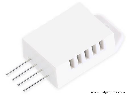
TTP223 Touch Sensor Module
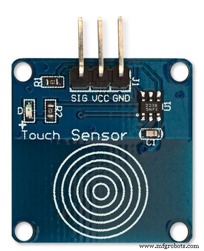
The touch Sensor Module is bolted to the front panel using the glass mounting bolts. The bolt goes through a 5mm hole drilled in the middle of the sensor.Note the mounting bolt is touched to trigger the sensor but is insulated from the sensor itself through plastic washers. Four of these modules are used in the clock one mounted on each corner of the glass.
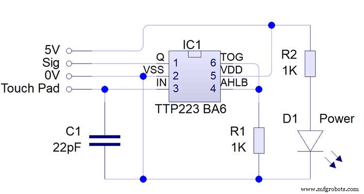
Note the LEDs are not required and are removed from the modules (just break them off) to save power.
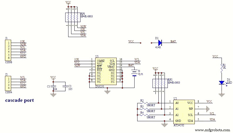
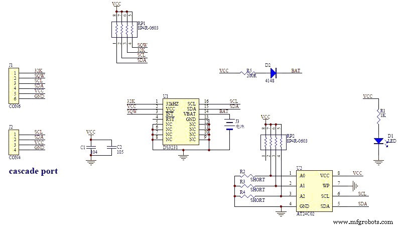
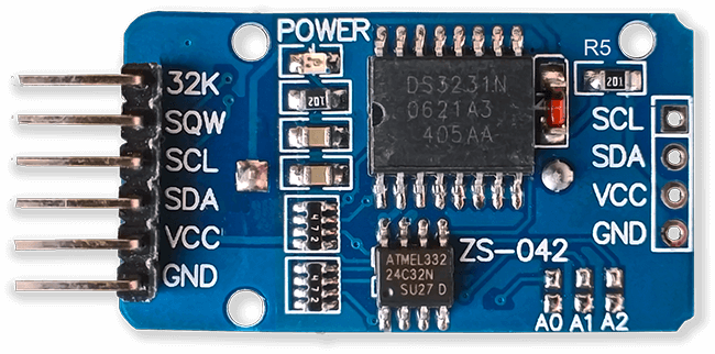
DS3231 AT24C32 I2C Precision Real Time Clock Module
My clock uses a DS3231 AT24C32 I2C Precision Real Time Clock Module.The module comes supplied with a Lithium-Ion rechargeable battery see diagram below. I use a non rechargeable battery so have removed resistor R5 from the module.
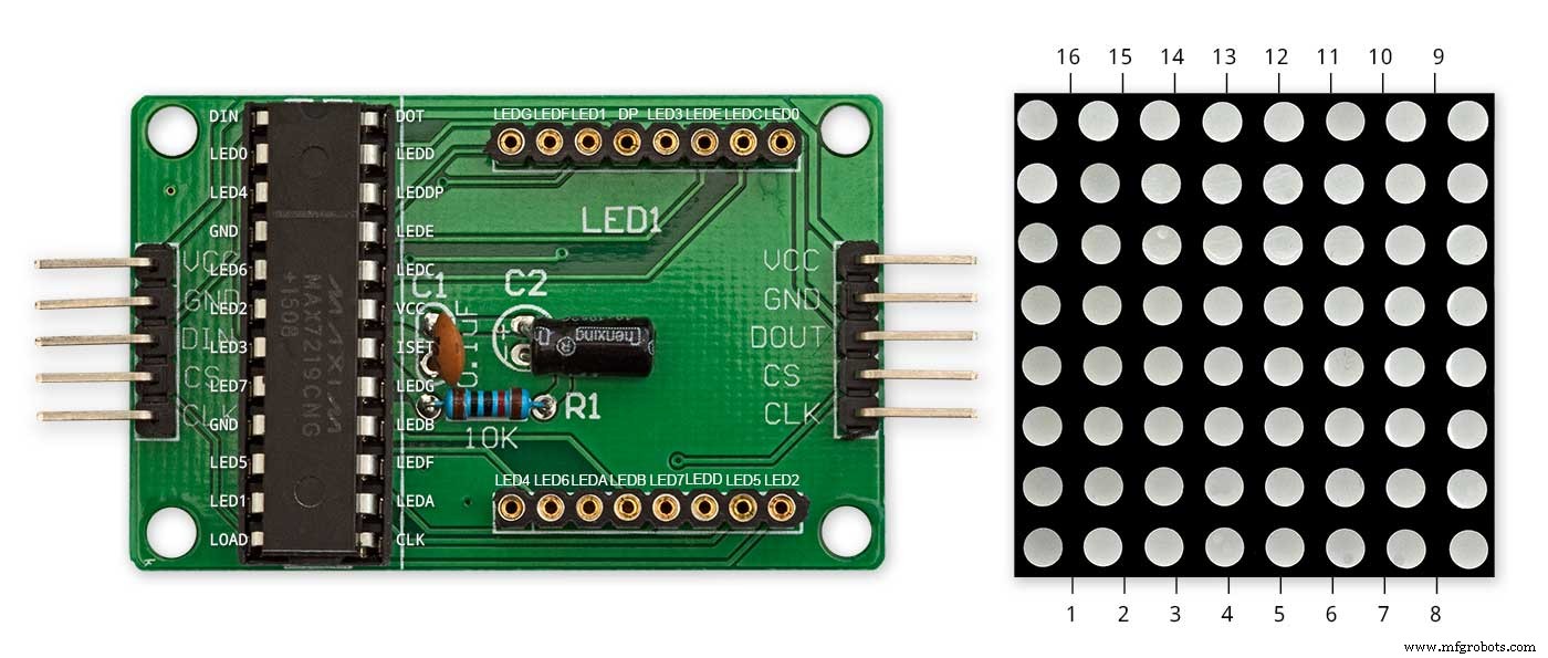
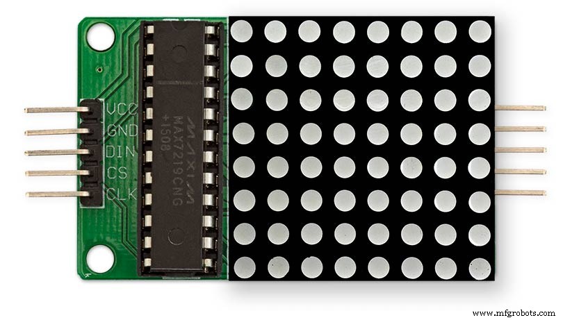
MAX7219 Display Module
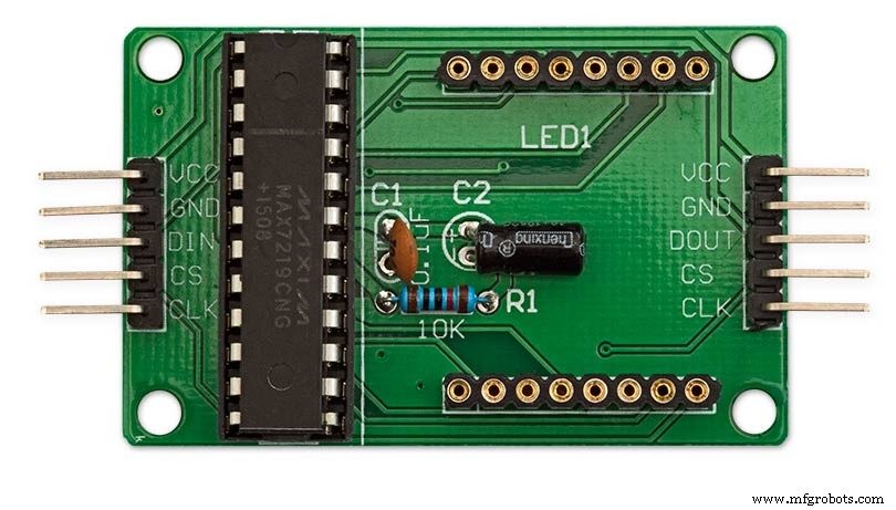
MAX7219 LED current limiting
The max current through the LEDs is set by a single resistor R1 on the module. The value of resistor can be found from the table below.
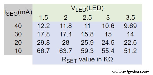
The module comes with a 10K resistor preinstalled but this can be removed and a resister to match your LEDs current added in its place. My LEDs Forward Voltage is 3.2v - 3.8v @ 20mA. They can handle 30mA max but for long LED life 20mA is best. I have used 22KΩ resistors which will limit the current to around 20mA when the light levels are at their peek.
See setting automatic brightness levels.
1088AS LED Dot Matrix display

1088AS LED Dot Matrix display view of lower edge Pins 1 to 8 left to right.
This is used for prototyping and is not required in the final project.
LDR
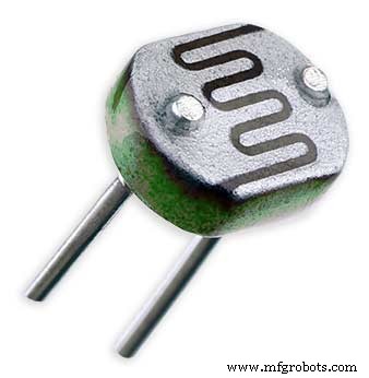
An LDR is used to sense the ambient light levels. The LDR is around 500Ω in bright light and 10MΩ in the dark.
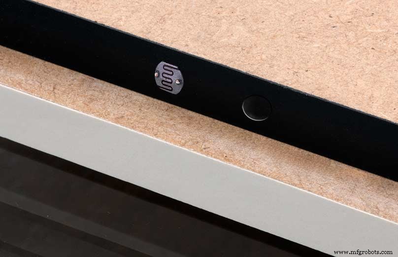
The LDR is positioned underneath the clock on the rear MDF panel.
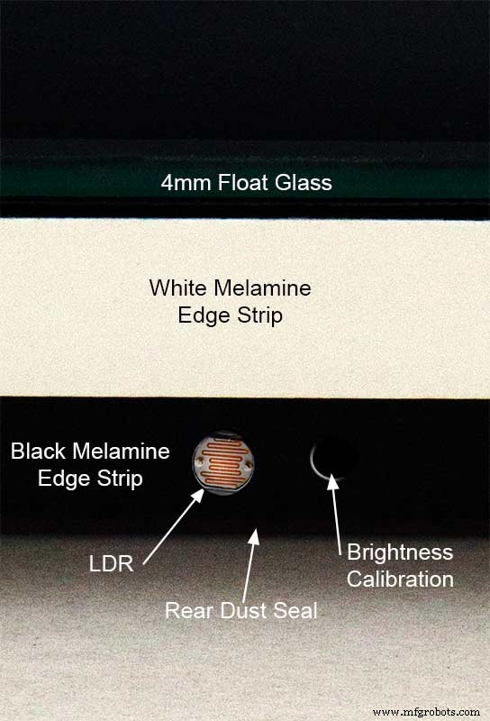
Next to the LDR is a hole to give access to the trimmer resister to calibrate the LED brightness control.
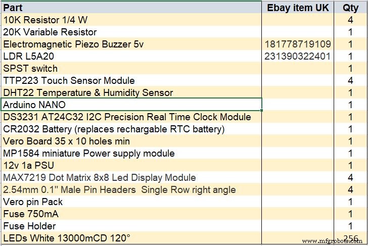
Component List
Step 18 Dust Seals
To prevent ingress of dust two dust seals are fitted.
On the rear MDF board a 2mm soft foam rubber dust seal is fitted. When the clock is hung on its hanging hooks the seal is under pressureand seals the back of the clock to the wall.
The seal is self adhesive and is fitted with a 5mm gap to the edge of the rear MDF board.
On top of the front board to prevent dust getting under the glass a strip of self amalgamating rubber is fitted 5mm from the board edge.
To prevent the glass from cracking when the Chicago bolts are tightened 4 small square of rubber are also fitted around the holes in the glass.
I punched holes for the Chicago Bolts in the rubber with a leather punch.
Step 19:Schematic
Nano Connections
The connections to the Arduino Nano. Download the full size file from the hardware section
MAX2719 connections


The 4 MAX7219 modules and the connected LED matrixes.
Note the LED display matrixes are rotated anti-clockwise 90 degrees from each other starting from display matrix 01.Display Matrix 01 input is wired to the Arduino CLK, DIN and LOAD the output is taken to the input of Display matrix 02 etc etc.
Step 20:Wiring Building the LED Matrixes
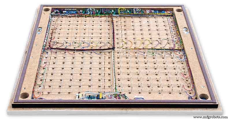
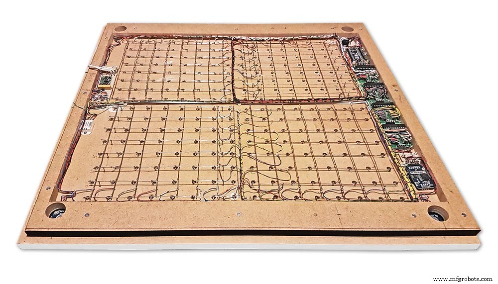
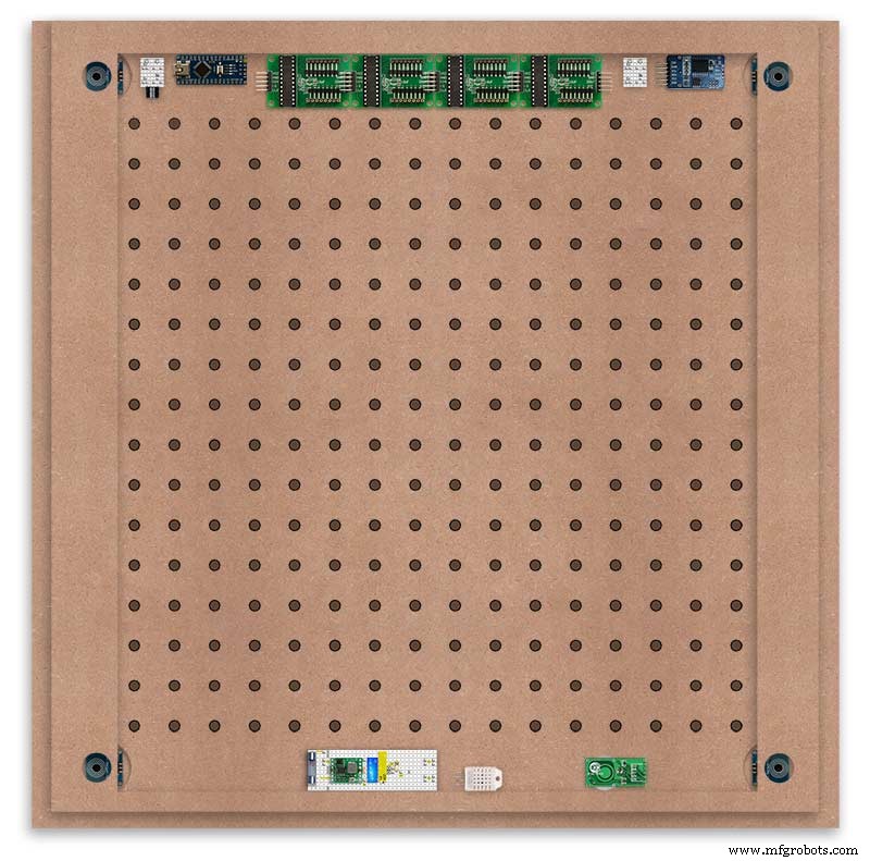
Module Locations

The module locations are shown above. The four sensors are located in the recesses on the main board behind the rear board. Holes are cut into the rear board to allow access for fit the Chicago Bolts/Sensor pads.
The four MAX7219 Display Modules are soldered together and are mounted in the centre top of the board. This keeps the data links between the boards as short as possible.
The Arduino Nano is mounted on the left of the MAX7219 Display Modules and the RTC on the right. The RTC battery holder on the base of the RTC module is recessed into the main board.
The Vero board containing the power module is located on the lower part of the board. There are two power distribution boards mounted on the top of the clock. The main 5v 2A feed cable is taken to both of these boards and power is then distributed to the other boards from these points.
The MAX7219 board power is fed from the left board and daisy chained through each board then taken out the forth board to ensure they are fed with 0v and 5v from both ends.
The LED locations are shown. The LED matrixes each contain 64 LEDs and are labelled 1 to 4.
These correspond to the 4 MAX 7219 modules mounted above numbered 1 to 4 left to right. Note this is the rear of the clock so number will be revearsed.
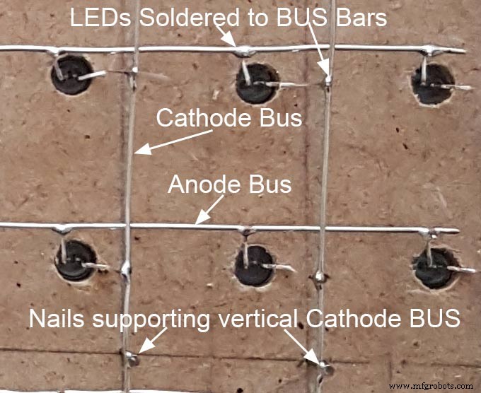
The LED Matrixes are built up off 2 types of BUS Bars per module. A Cathode Bus at 10mm high and an Anode BUS bar at 2mm high.
There are 8 Cathode and 8 Anode BUS Bars per module. Each module has 16 x 15mm panel pins hammered into the board in the position shown to support the 10mm high Cathode BUS.
The 15mm panel pins are hammered in 5mm (I used a 10mm piece of metal bar as a gauge) leaving 10mm as Cathode BUS bar support pins.
As shown above the pins correspond with the thick parts of the board not the recess for the LEDs on the front of the board. Note the LED recess is on the front of the board and can't be seen from the back.

0.9mm copper wire is then soldered to each pair of pins to form the Cathode BUS Bar.
Note the rotation of each module and also the modules are in reverse as it is the back of the board the LEDs are connected to.
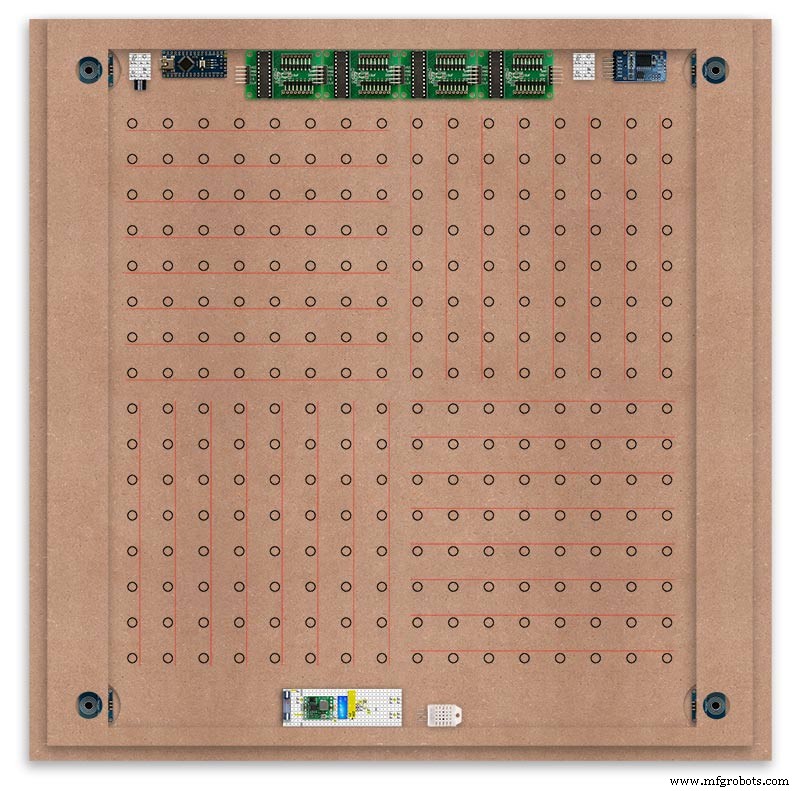
The Anode BUS Bars are shown below in Red and are supported off each LED Anode about 2mm off the MDF board. No Pins required.

Both Cathode &Anode BUS Bar locations are shown below.
Each LED is connected to an Anode and Cathode of the Matrix.
Step 21:Wiring the LEDs
LEDs
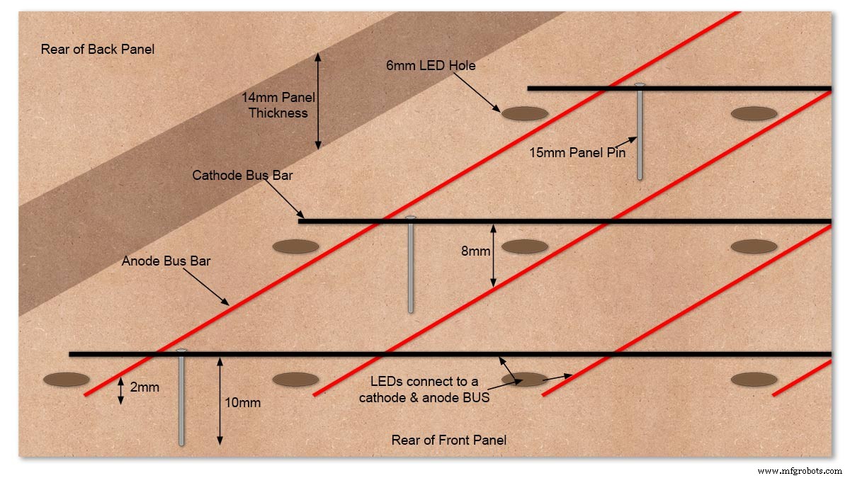
Diagram showing Bus Bar layout with panel pins supporting the Cathode Bus. This module has horizontal Cathode and vertical Anode Bus Bars.
Close up section of Module wiring.The Cathode BUS Bars run vertically and the Anode BUS Bars run horizontally on this module. The Anode &Cathode BUS Bars have an 8mm vertical separation.
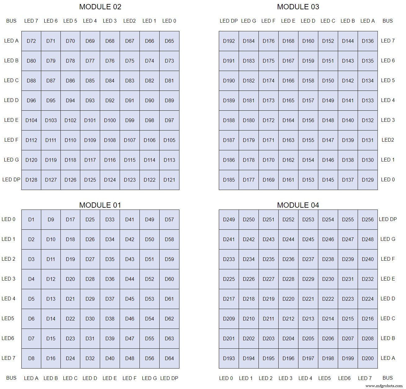
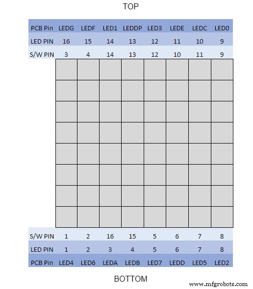
The LEDs are connected to the matrixes and MAX7219 modules from the rear. The LED positions will be reversed and of course rotated 90° relative to the next module. This makes it very complicated connecting the correct LEDs and Bus bars from the rear of the board. The table below shows the LED positions in the blue boxes with the BUS Bar matrix position in black around the outside as they appear from the back of the front MDF board.
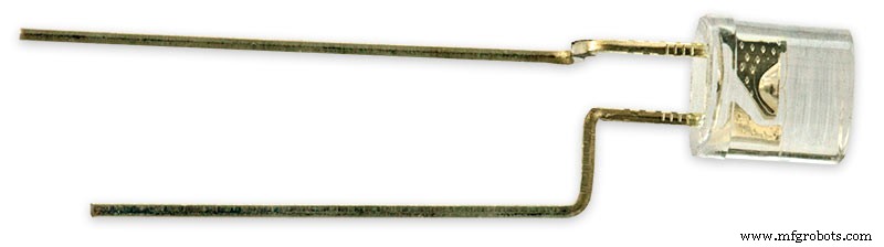
The LEDs are bent in a jig to keep the position in the display constant and to speed up construction. Each LED has four bends two on each leg that's 1024 in total! The Cathode leg is bent 90° from the Anode.
The Matrix grids are wired to the corresponding pins on the MAX7219 modules according to the layout table.
There are 16 wires to each module.
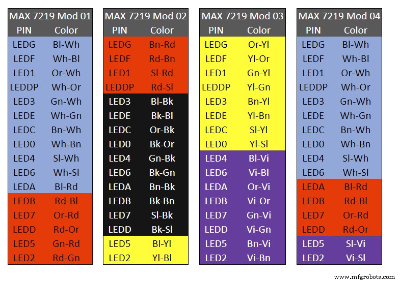
Table 1 Module LED Matrix Wiring Colour Code is shown above.
Each Module has 16 wires connecting it to the LED Matrixes. I have used 50pr 0.5mm cable so the last 14pr colours are duplicated. On Mod 4 I went out of order and missed out the Sl/Vi at the start so have put it in at the end.
Step 22:Wiring Modifying the MAX7219 Modules
Before wires can be connected to the MAX 2917 modules they will need to be modified.
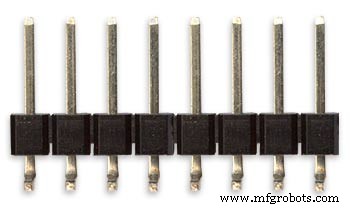
Two sets of 8 90° pin connectors will to be soldered to the lower edge of the existing LED matrix connector.

Modified MAX7219 module with 90° pin connectors soldered in place to the bottom of the old LED Matrix connectors.
Wires are taken away from these points to the LED matrix on the main MDF board as per the LED Matrix Wiring Colour Code table on the previous step.
Side view showing the pins soldered to the side of the old LED Matrix connector pins just above the PCB.
Note if your MAX7219 Module does not have surface mount components the 90° pin connectors may need to be trimmed back so they don't foul R1, C1 or C2.
MAX7219 LED current limitingThe max current through the LEDs is set by a single resistor R1 on the module. The value of resistor can be found from the table below.

The module comes with a 10K resistor preinstalled but this can be removed and a resistor to match your LEDs current added in its place.
My LEDs Forward Voltage is 3.2v - 3.8v @ 20mA. They can handle 30mA max but for long LED life 20mA is best. I have used 22KΩ resistors which will limit the current to around 20mA when the light levels are at their peek.
Note this sets the max current through your LEDs actual brightness is controlled by the LDR/software/ trimmer resistor and will usually be far less than this.
Setting Automatic Brightness Levels
The clock automatically senses the ambient light and adjusts the LEDs accordingly.
When first installed the clock will need to be calibrated to the maximum light levels in its actual location.

Connect a mobile, laptop/tablet etc via a suitable cable to the mini USB port of the clock and open an app to monitor the serial port.
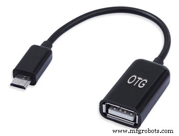
I use Slick USB 2 Serial Terminal on my S7 via an OTG cable and USB to mini USB cable.
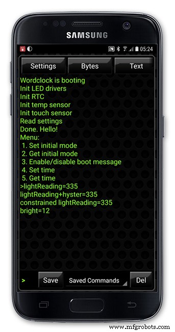
The clock will reboot and after the initial start screen you will see the following data updating down the screen.
You don't need to worry about lightReading or constrained lightReading+hyster just light reading, and bright.
With the clock in position and the ambient light at its maximum levels carefully insert a flat bladed jewellers screwdriver into the access hole just to the right of the light sensor.
Turn the screwdriver slowly until the light reading =600 (or your level set in brightness.cpp) and bright =15.
Your clock will now go to max brightness when the ambient light is at its maximum.
If you turn the screwdriver too far the light reading will go over 600 but the bright reading will not increase.
If you want the clock to be dimmer right across the range of ambient light levels adjust the light reading to a level less than 600 at max ambient light levels.
Note when bright=15 this will output the max current to the LEDs. The max current is set by R1( RSET) on the MAX7219 module and this should be chosen for your type of LED used in the display.
Step 23:Wring Mini USB Port
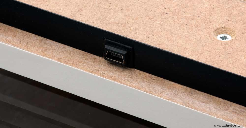
To allow adjustment/checking of light levels and programming of the clock a Mini USB socket is cut into the right hand side of the rear MDF sheet.
I have used a 25cm 90° Right angle Mini USB Male to Female Extension Cable and stripped back the insulation sleeve and shielding to expose the wires. This allows the cable to bend around the sharp angles and tight spaces of the enclosure.
Step 24:PIR Controlled Display Shutdown
This is optional as a Doppler Radar module can be fitted inside the clock instead.
See next section.
The PIR when enabled on the word clock menu (bott left PIR On, bott right PIR Off) turns on the display when movement is detected in the room.
When no movement is detected the display turns off after a set period of time. When the PIR is enabled the displays shows "PIR ON" and when disabled (display always on) it shows "PIR OFF" Note when the PIR is not enabled the display is always On.
The PIR module is fitted remote from the clock in a modified chrome light switch box. The box is cut into a plasterboard wall and also contains a switch to turn the clock off. The module itself is very small and can be mounted in a tiny enclosure if you don't want it on show. It will not work behind glass so if you wanted to mount it on the clock a hole would need to cut in the glass. This is very easy to do with a large hole cutter.
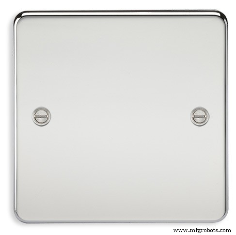
A blank chrome switch plate and back box are used to house the power switch and PIR module.
Two holes are drilled in the blank switch plate for the power switch and PIR lens.
The hole are centre punched, pilot drilled and then drilled out just big enough for a step cutter to fit through. The hole for the PIR diffuser is cut just big enough for the lens to go through with a friction fit.
The completed switch plate.
The 12 volt supply +ve is terminated on the switch with the 0v terminated on the earth screw.
12 volts is then fed back upto the clock PSU Vero board from the other side of the switch and again the earth screw. 5 volts are fed from the clock PSU Vero board to supply the PIR module.
The 5 volts and PIR sensor wire to the clock terminate on PCB header sockets. These are is plugged into the PIR Module header pins. The sync cable is terminated on a header pins and connects to the Master Clock 30 second sync cable via a single header socket.
The PIR has 2 trimmer resistors for adjusting sensitivity and also length of time the PIR &display stay activated.
PIR On/Off Control:The PIR is turned on and off in word clock mode by touching the bottom left sensor to turn the PIR on or by touching the right sensor to turn the PIR off. Note when the PIR is set to off the display stays on permanently. When you change the PIR setting the work "PIR ON" or "PIR OFF" is displayed for 5 seconds.
When initial power up the default is PIR off if you switch the PIR On straight away the display will go off as the PIR takes a minute or so to initialise before detecting movement.
Photo 6 &7 "PIR ON" or "PIR OFF" are displayed for 5 seconds when PIR setting is changed.
Step 25:Doppler Radar Control Option
Optional Doppler Radar Module can be added in place of the PIR above.
The Doppler Radar when enabled on the Word Clock menu (bott left PIR On, bott right PIR Off) turns on the display when movement is detected in the room. A check is made for motion on every quarter hour. When no movement is detected the display turns off until movement is detected again.
When the PIR is enabled the displays shows "PIR ON" and when disabled (display always on) it shows "PIR OFF" Note when the PIR is not enabled the display is always On. Unlike PIR modules the Doppler Radar module can see through glass and plastic and is fixed into the case of the clock behind the glass and PVC sticker. The module has a range of around 5m or 16' 5".
Doppler Radar Module fixed inside the case. A hole is drilled in the front panel to allow the module to monitor the room.
Front panel showing hole through to the Doppler Radar module microwave sensor.
The module is hidden from view behind the PVC sticker and glass.
Step 26:PIR/Doppler Radar On Off Control
The PIR is turned on &off in word clock mode by touching the bottom left sensor to turn the PIR on or by touching the right sensor to turn the PIR off.
Note when the PIR is set to off the display stays on permanently.

When you change the PIR setting the work "PIR ON" or "PIR OFF" is displayed for 5 seconds.
When initial power up the default is PIR off if you switch the PIR On straight away the display will go off as the PIR takes a minute or so to initialise before detecting movement.
Step 27:Setting Automatic Brightness Levels
The clock automatically senses the ambient light and adjusts the LEDs accordingly.
When first installed the clock will need to be calibrated to the maximum light levels in its actual location. Connect a mobile, laptop/tablet etc via a suitable cable to the mini USB port of the clock and open an app to monitor the serial port. I use Slick USB 2 Serial Terminal on my S7 via an OTG cable and USB to mini USB cable.

The clock will reboot and after the initial start screen you will see the following data updating down the screen.
You don't need to worry about lightReading or constrained lightReading+hyster just light reading, and bright.With the clock in position and the ambient light at its maximum levels carefully insert a flat bladed jewellers screwdriver into the access hole just to the right of the light sensor. Turn the screwdriver slowly until the light reading =600 (or your level set in brightness.cpp) and bright =15. Your clock will now go to max brightness when the ambient light is at its maximum. If you turn the screwdriver too far the light reading will go over 600 but the bright reading will not increase.
If you want the clock to be dimmer right across the range of ambient light levels adjust the light reading to a level less than 600 at max ambient light levels.
Note when bright=15 this will output the max current to the LEDs. The max current is set by R1( RSET) on the MAX7219 module and this should be chosen for your type of LED used in the display.
Step 28:Setting the Clock
The clock is set in the digital clock mode by touching the bottom left sensor.
The hour digits will now flash twice a second to indicate the clock is in time setting mode.In this mode the sensors have the following functions.
Top right - steps the hours or mins digits up
Top left- steps the hours or mins digits down
Bottom left 1sr press - enters the time setting mode selecting hours digits
Bottom left 2nd press -selects the mins digits for changing
Bottom left 3rd press -exits time setting mode and sets the time
Bottom right - resets the seconds to 00
Step 29:Synchronisation
If you have connected a 30 second master clock sync cable then the clock will jump back or forward to 30 seconds when out of time setting mode. If you don't have a Master Clock to sync to then the clock will fall back on the on board temperature compensated real time clock which in itself is a very precise quartz clock.
Just reset the seconds roughly in sync to the seconds (within 10 seconds either way) and wait for the clock to sync once out of time setting mode.
The animated loop below shows the Word Clock is running fast by several seconds. A synchronisation pulse is received from the Master Clock every 30 seconds on the minute and half minute synchronising the clock on 30 seconds.
The clock will ignore the 30 second synchronisation pulse from the Master Clock at 0 seconds. Note clock synchronisation only happens when the Word Clock is 20 seconds past and 20 seconds to a minute. In normal operation the sync pulse corrects the clock to within a fraction of a second so you will see the word "SYNC" appear with no visible correction to the seconds.
Note the synchronisation pulse is received every 30 seconds but the clock will ignore pulses at 0 seconds.
Step 30:Software &Making Changes
The software can be downloaded from the software tab and contains the following modules.
Program Files Modules
Brett_wordclock_v4_3.ino Main program, latest update includes shortened code saving 10% in size.
Thanks to srdevil for providing the updated code for this seconds display.
brightness.cpp/.h Brightness autoadjustment
character.cpp/.h Character (digit) definitions
credits.cpp/.h Ending Credits
display.cpp/.h Display &LED functions
life.cpp/.h Game of Life
serial.cpp/.h Serial port setup menu
simon.cpp/.h Simon Says game
temphum.cpp/.h Temperature &Humidity displa
tetris.cpp/.h Tetris game
time.cpp/.h Wordclock, digital clock
timeanalog.cpp/.h Analogue clock
touchbuttons.cpp/.h Touch buttons, mode switching
Third party libraries:
Chronodot.cpp/.h Chronodot library (for DS3231)
DHT.cpp/.h Temperature sensor library (for DHT22)
LedControl.cpp/.h LedControl library (for MAX7219)
stc.cpp/.h/platform.h Simple Tetris Clone library
pitches.h Note frequencies from the Arduino webpage
When you want to make changes to my code you can compare my code to the "Catalan Code" to make it easier to understand what changes you need to make. I have added //Brett to my code to highlight my changes.
Changing the code.
If like me you are not very good at coding just play around with the code to get an understanding of how it works.
I just save a different version each time I make even a tiny change. This way if I mess up I can go back a version and start again.
If you are keeping my linear seconds display update the version number on the display so you know what version you are trying out each time. This is done in the module credit.h around line 47.
It would take far too long to explain all the code but here is a very brief guide on how to change the words and when they are displayed.
The WORDS are set in time.h
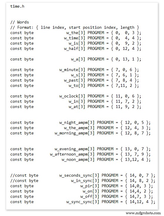
On line 52 we have
const byte w_the[3] PROGMEM ={ 0, 0, 3 };
The word "THE" is described in this line with the LED location in the curly brackets "{ 0, 0, 3 }"
This is the co-ordinate of the LEDs we are gong to light when we call "w_the"
The LED matrix numbers starts top left and start from 0 so "{ 0, 0, 3 }" is the first LED across and down the 3 just means the 3 LEDs across including this one will light. As the letters THE are in this position the word "THE" is displayed.
Similarly the word "TIME" would be lit by lighting the four LEDs here { 0, 4, 4 } or row 0, 5th LED along and light 4 LEDs (remember to count from 0).
Working you way down the page shows the position of all the words.
Controlling when words are lit
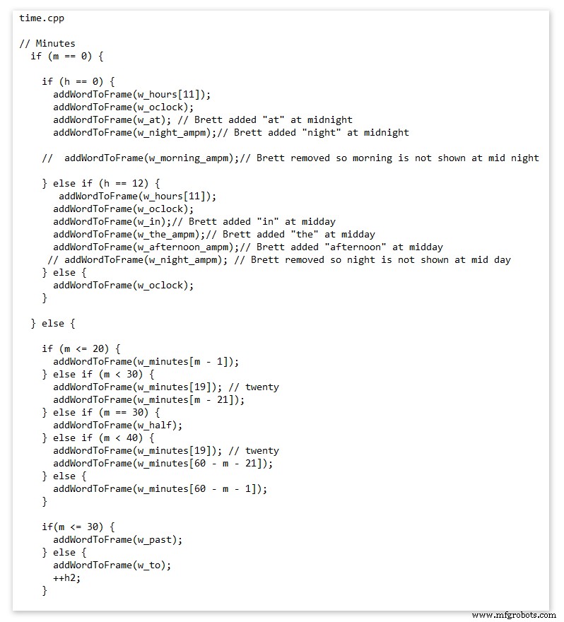
This happens in the module time.cpp
Here you just make a list of rules to tell the clock what words to light at certain times.
Pic above shows part of the code starting with line 695
At midnight we want to make the clock say "THE TIME IS TWELVE OCLOCK AT NIGHT"
Midnight is 00 00
"THE TIME IS" is always displayed from lines 687
So we add the rules if minutes are 0, then if hours are 0 show the word for hours "TWELVE" and the word "OCLOCK" the word "AT" and the word "NIGHT"
If you follow the code down all the possible time combinations are covered.
Analogue Clock Code Change - increase in time definition One of the comments sent to me by srdevil was some code changes. His comment can be seen below.
I have not had time to test the code but have included it below if you want to try it out.
" If the time is 18:00, it points up (long leg) and down (short leg). But when the time is 18:59, it still points totally down (short leg) so it looks like the time is 17:59 on a normal clock. My brother change the code so that if it is>HH:15 the small pointer moves already to the next number. As of this we also increased the resolution in the part between>HH:15 -
Code on the comments section or can be seen here http://home.btconnect.com/brettoliver1/Word_Clock/Word_Clock.htm#analogeclock
Code
- Brett_wordclock_v4_5.zip
Brett_wordclock_v4_5.zipArduino
Load into Aduino IDENo preview (download only).
Github
https://github.com/wouterdevinck/wordclockhttps://github.com/wouterdevinck/wordclockGithub
https://github.com/svcabre/wordclockhttps://github.com/svcabre/wordclockMy Word Clock on GITHUB
Schematics and code https://github.com/brettoliver/wordclockAangepaste onderdelen en behuizingen
Vinyl Sticker Design in Inkscape (free to download) change as required brett11_print_ready_6bbpMTDyFa.svgSchema's
Schemaic showing main board connections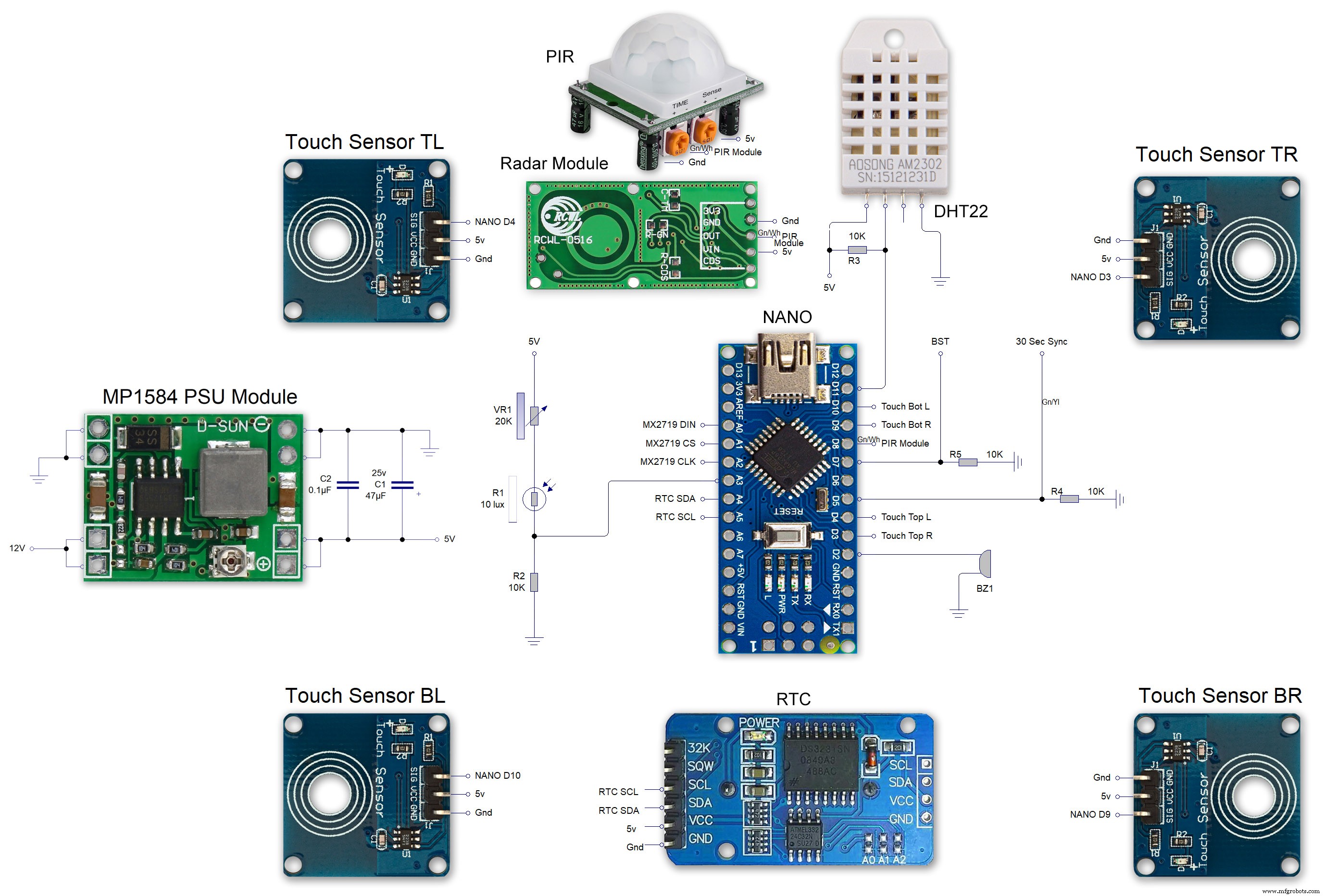 MAX7219 7 segment display module 01 LED connections
 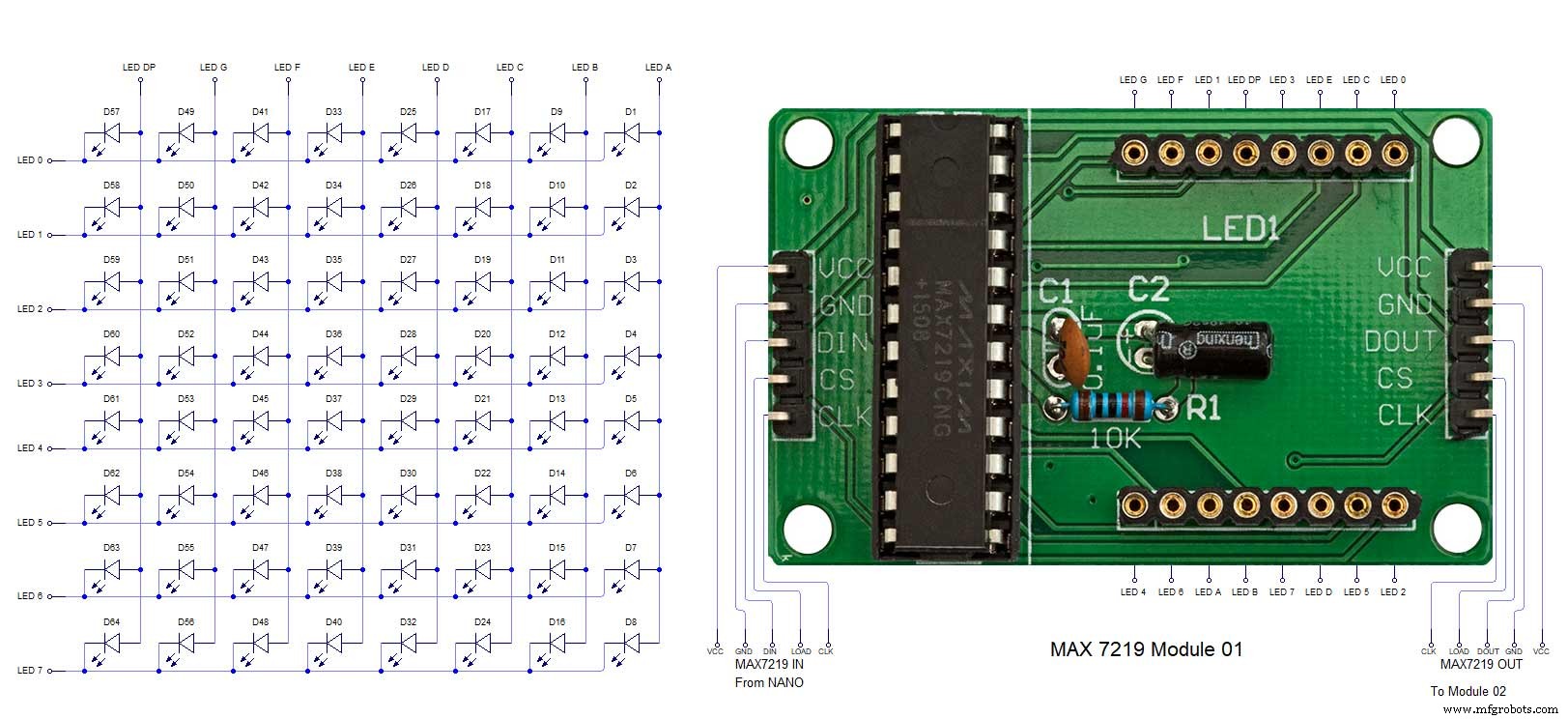 MAX7219 7 segment display module 02 LED connections
 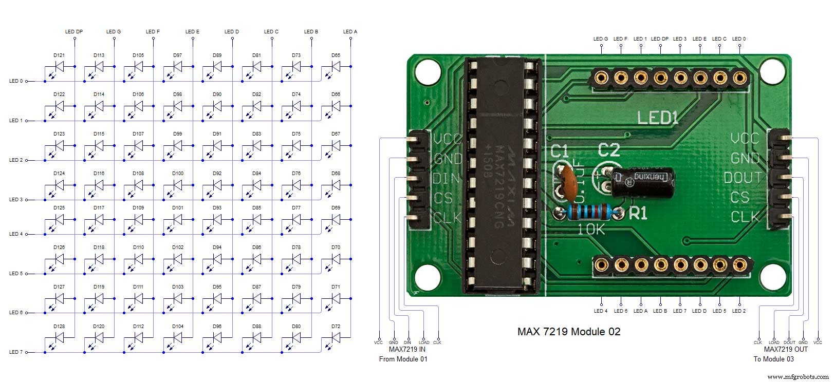 MAX7219 7 segment display module 03 LED connections
  MAX7219 7 segment display module 04 LED connections
Productieproces
- Koekoeksklok
- 3D-printen met siliconen — is het zover?
- Analoge sensoren uitlezen met één GPIO-pin
- DIY eenvoudigste IV9 Numitron-klok met Arduino
- Python Timeit() met voorbeelden
- Eenvoudige Word Clock (Arduino)
- Arduino klok met islamitische gebedstijden
- Verminder knelpunten met 5 eenvoudige tools
- Arduino Temp. Monitor en realtimeklok met 3.2-weergave
- Italiaanse Word Clock
- Eenvoudige wekker met DS1302 RTC