Een overzicht van bedienings- en detectiemechanismen in op MEMS gebaseerde sensorapparaten
Abstract
In de afgelopen decennia is de vooruitgang in micro-elektromechanische systeem (MEMS) -apparaten sterk gevraagd voor het integreren van de economisch geminiaturiseerde sensoren met fabricagetechnologie. Een sensor is een systeem dat meerdere fysieke inputs detecteert en erop reageert en deze omzet in analoge of digitale vormen. De sensor zet deze variaties om in een vorm die kan worden gebruikt als een markering om de apparaatvariabele te bewaken. MEMS vertoont uitstekende haalbaarheid in miniaturisatiesensoren vanwege de kleine afmetingen, het lage stroomverbruik, de superieure prestaties en de batchproductie. Dit artikel presenteert de recente ontwikkelingen in standaard bedienings- en detectiemechanismen die op MEMS gebaseerde apparaten kunnen dienen, wat naar verwachting een revolutie teweeg zal brengen in bijna veel productcategorieën in het huidige tijdperk. De aanbevolen principes van bediening, detectiemechanismen en real-life toepassingen zijn ook besproken. Een goed begrip van de aandrijf- en detectiemechanismen voor de MEMS-gebaseerde apparaten kan een cruciale rol spelen bij een effectieve selectie voor nieuwe en complexe toepassingsontwerpen.
Inleiding
Sensoren en actuatoren worden gezamenlijk aangeduid als transducers, die de functie hebben om signalen of stroom van het ene energiedomein naar het andere te transformeren [1, 2]. Een breed scala aan transductie-instrumenten is bedoeld om fysieke signalen om te zetten in elektrische signalen (d.w.z. sensoren). Bovendien worden de uitgangssignalen verder verwerkt door elektronische systemen met behulp van geïntegreerde schakelingen (IC's), net zoals het omzetten van elektrische signalen in fysieke signalen (d.w.z. actuatoren) [3]. Sensoren zijn in het bijzonder de apparaten die fysieke fenomenen (d.w.z. trillingen, druk en stroming) of samenstellingsvariaties (elektrische geleidbaarheid en potentiële waterstof (pH)) detecteren en bewaken. Sensoren zetten variaties om in een bepaalde vorm die kan worden gebruikt om gemeten variabelen te markeren of te regelen [4, 5], terwijl actuatoren worden gebruikt om mechanische beweging en kracht/koppel te produceren. Met andere woorden, detectie kan breed worden gedefinieerd als energietransductieprocessen die resulteren in perceptie, terwijl actuatie energietransductieprocessen zijn die acties produceren. Sensoren bestaan uit drie delen; detectie-element om de fysieke en chemische grootheid te detecteren, transducer om de gedetecteerde parameter om te zetten in een elektrisch signaal, uitleesapparaat zoals een computer die wordt gebruikt om het geconverteerde signaal te lezen en te interpreteren.
De prestaties van sensoren zijn geëvalueerd door verschillende karakteristieke parameters, zoals gevoeligheid, resolutie en nauwkeurigheid enz. Terwijl gevoeligheid de minimumwaarde van de doelstofconcentratie bepaalt. Resolutie verwijst naar een verhouding tussen de maximaal gemeten magnitudes tot het kleinste deel dat kan worden bepaald. Tegelijkertijd wordt nauwkeurigheid gedefinieerd als de mate van onzekerheid in de meting ten opzichte van een absolute standaard, en kan deze direct de kwalitatieve analyse van de sensor beïnvloeden [6]. Terwijl de detectielimiet (LOD) de laagste hoeveelheid van een stof is die door de sensor kan worden onderscheiden, waarbij het vermogen van een sensor om een bepaalde stof te identificeren. Bovendien is de responstijd de specifieke tijdsperiode waarin de concentratie een bepaalde limiet bereikt wanneer de sensor een waarschuwingssignaal afgeeft, en de hersteltijd is de periode na het detectieproces van het detectiemateriaal dat nodig is om te herstellen en zijn basislijnstatus te herstellen.
In de afgelopen decennia hebben vorderingen in de fabricage van micro-elektronische apparaten geleid tot overtuigende, nauwkeurige en hoogwaardige apparaatsystemen. De technologie is zo ver uitgeknepen dat we apparaten zo klein kunnen maken dat ze niet zichtbaar zijn voor het menselijk oog. Micro-elektromechanische systemen (MEMS) omvatten de innovatie van de kleine apparaten die de modellen als sensoren of actuatoren kunnen voorstellen. Continue ontwikkeling op het gebied van MEMS houdt een belofte in voor de geoptimaliseerde en kostenbesparende geminiaturiseerde elektronische apparatuur [7,8,9]. Typische afmetingen van MEMS-apparaten worden over het algemeen gemeten in tientallen of honderden microns. Het gebruik van dezelfde fabricagemethoden wordt als het bouwen van microprocessors. Momenteel kunnen sensoren en actuatoren op een vergelijkbaar schaalniveau worden gebouwd met de microprocessorchips. In recente ontwikkelingen, microschaal fabricage van batches van druk, temperatuur, traagheid enz., zijn sensoren gedemonstreerd voor batchschaal met behulp van een vergelijkbare chipverwerkingseenheid. Door een systeem nauwkeurig op een chip te plaatsen, kunnen complexe systemen worden bediend [10, 11].
MEMS is een technologie die is gefabriceerd met behulp van halfgeleidermaterialen en die mechanische componenten, sensoren, actuatoren en elektronische elementen op een algemeen siliciumsubstraat bevat met kenmerken van enkele millimeters tot micronmeters [12]. Deze systemen kunnen op microschaal detecteren, besturen en activeren, die afzonderlijk of in bulk kunnen werken om een effect op macroschaal te produceren. MEMS-technologie heeft de combinatie van micro-elektronica met microbewerkingstechnologie op een typische Si-wafer in typische metaaloxide-halfgeleidende apparaten overwogen [13]. In de afgelopen tijd is de MEMS-technologie aanzienlijk gegroeid voor het erkennen van verschillende soorten natuurlijke sensoren en actuatoren. Bovendien is het gebruikt in geminiaturiseerde sensorproductie in een groot aantal toepassingen vanwege de lage vermogens [14], snelle respons, arrayfabricage bij mechanische maatregelen, gemak, goedkoop en betere gevoeligheid. Aanzienlijk is dat de verhouding tussen oppervlakte en volume van detectiemateriaal aanzienlijk is vergroot, wat uiteindelijk de bedrijfstemperatuur van de op metaaloxide gebaseerde sensor heeft verlaagd en de vraag naar expansiematerialen heeft doen toenemen [15,16,17].
Onlangs hebben op metaaloxide gebaseerde sensoren zoals titaniumdioxide (TiO2 ), tindioxide (SnO2 ) en zinkoxide (ZnO) is het meest aantrekkelijke type sensoren geworden voor de detectie van gassen [18]. Het werkingsprincipe van de metaaloxidehalfgeleidertechniek (MOS) hangt af van de verandering in soortelijke weerstand van een metaaloxidehalfgeleider die als acceptormateriaal wordt gebruikt bij blootstelling aan een analytgas tijdens detectie [19]. De hoge gevoeligheid van deze sensoren zou echter alleen worden bereikt bij verhoogde bedrijfstemperaturen [20], daarnaast zijn er ook selectiviteitsproblemen. Een alternatieve benadering is om het te combineren met andere detectiecomponenten, met name nanodeeltjes van edelmetaal (dwz Au, Ag, Pd en Pt), om de bovengenoemde barrières te overwinnen, vanwege de extreme specifieke voordelen van chemische en elektronische sensibilisatie [21,22] ,23].
MEMS-apparaten kunnen in de MEMSCAP US worden gefabriceerd via de MUMP's (Multi-User MEMS)-procedures. MUMPs is een winstgevend programma dat praktische, evidence of idea MEMS-creatie geeft aan industrieel en academisch onderzoek. Over het algemeen biedt MEMSCAP drie standaardprocedures als een belangrijk aspect van het MUMP-pakket:PolyMUMP's, beschreven als een drielaagse polysilicium-microfabricageprocedure, MetalMUMPs, dat is een gegalvaniseerde nikkelprocedure, en SOIMUMP's, gepresenteerd in een microfabricageprocedure van silicium op isolator [24]. MEMS-procedures zijn ontwikkeld op basis van de unieke technologieën van de fabricage van halfgeleiderapparaten:afzetting, patroonvorming en etsen van materiaallagen [7, 25]. De stappen van de fabricagetechnologie van MUMP's worden weergegeven in de ontwerphandboekregel [24]. Ondanks fabricagetechnologie zijn MEMS-sensoren op grote schaal gebruikt als instrumentatie of menselijke comfortkwesties in industriële en huishoudelijke toepassingen. Vanwege de diverse werkomstandigheden van MEMS-sensoren in de verschillende toepassingsgebieden (van intern gebruik tot gebruik buitenshuis), zijn verschillende soorten MEMS-sensoren gemodelleerd op basis van verschillende werkingsprincipes en verschillende sensormaterialen. De MEMS-sensoren zijn essentieel in gasdetectiesystemen, waaronder sensoren voor vochtigheid en giftige gassen [19].
MEMS is een breed domein en bestrijkt bijna elk aspect van ons huidige leven, als sensoren en actuatoren. De opkomende domeinen van elektronische microsystemen, waaronder bijna alle productcategorieën in geminiaturiseerde vormen, hebben bijgedragen aan een snelle ontwikkeling op het gebied van bedienings- en detectietechnieken in hun productie- en integratieprocessen. De doeltreffendheid van een gerichte toepassing is in grote mate afhankelijk van de juiste selectie van een specifieke actuator. Bovendien hangt het basisrendement van de actuator af van verschillende factoren, zoals stroom- en besturingsmethoden, compatibiliteit, de mate van verpakking die nodig is en kosteneffectiviteit. Dit artikel biedt een grondige analyse van de MEMS-aandrijf- en detectietechnologieën die zijn onderzocht voor hun functionele toepassingen, met de nadruk op veel voorkomende vormen van transductie, om de vooruitgang van dit opkomende gebied te bevorderen en tegelijkertijd deze hoofdfactoren aan te pakken. De rest van het papier is als volgt ingedeeld. Deel II introduceert de micro-elektromechanische systemen. Sectie III geeft een kort overzicht van de activeringsmechanismen (verschillende principes en benaderingen om MEMS-apparaten te activeren zijn:elektrostatische, elektrothermische, elektromagnetische en piëzo-elektrische activering). Sectie IV introduceert een kort overzicht van de detectiemechanismen, waaronder piëzoresistieve, capacitieve en optische detectiemechanismen, en sectie V presenteert een verdere discussie over de vooruitzichten van op MEMS gebaseerde apparaten, tot slot geeft sectie VI de conclusies en toekomstige trends.
Micro-elektromechanische systemen
De eerste verschijning van wat tegenwoordig bekend staat als MEMS-technologie gaat terug tot 1 april 1954, toen Smith (1954) een artikel publiceerde in het Bell Telephone Lab als een fysieke recensie. Dit is de eerste beschrijving van enkele van de spanningsgevoelige effecten in silicium en germanium, piëzoweerstanden genoemd [26]. MEMS is niet de belangrijkste afkorting die vooral redelijk is vanwege de enorme uitgestrektheid en het assortiment van apparaten en systemen die zijn geminiaturiseerd (d.w.z. het veld is niet alleen micro-, elektrische en mechanische systemen). Niettemin wordt de afkorting MEMS meestal gebruikt om het hele veld aan te duiden (dwz alle apparaten die het resultaat zijn van andere microbewerkingen dan IC), ook geschreven als micro-elektromechanisch, micro-elektromechanisch of micro-elektronisch en MEMS in de Verenigde Staten) [3] . Verschillende namen voor dit algemene gebied van miniaturisatie omvatten Microsystems Technology (MST), beroemd in Europa [27], en Micromechanica beroemd in Azië [28]. MEMS-apparaten omvatten een breed scala aan domeinen om informatie uit de omgeving te meten en om te zetten in bruikbare elektrische signalen. Er zijn zes belangrijke energiedomeinen:
- 1.
Elektrisch domein (betreft elektrisch veld, stroom, spanning, weerstand, lading, capaciteit, inductantie, diëlektrische constante, polarisatie en frequentie).
- 2.
Chemisch domein (inclusief samenstelling, reactiesnelheid, concentratie, pH en oxidatie- of reductiepotentieel).
- 3.
Mechanisch domein (inclusief lengte, breedte, oppervlakte, afgeleiden van alle tijden zoals snelheid, versnelling, massastroom, volume, kracht, druk, koppel, akoestische golflengte en akoestische intensiteit).
- 4.
Thermisch domein (inclusief temperatuur, stroming, warmte, soortelijke warmte, entropie en toestand van welke materie dan ook).
- 5.
Stralingsdomein (betrekking hebben op intensiteit, fase, polarisatie, golflengte, reflectie, transmissie en brekingsindex).
- 6.
Magnetisch domein (inclusief veldintensiteit, permeabiliteit, fluxdichtheid en magnetisch moment).
Deze energiedomeinen en veel voorkomende parameters daarin zijn samengevat in (Tabel 1). De totale energie binnen een systeem kan in meerdere domeinen naast elkaar bestaan en kan onder de juiste omstandigheden tussen verschillende domeinen verschuiven [1, 29].
Volgens de werking van de ontworpen chip, kan MEMS worden onderverdeeld in verschillende categorieën. Het kan worden gebruikt om de detectie uit te voeren voor het meten, bewaken en detecteren van gevaarlijke gassen. Een andere classificatie is het gebruik van MEMS als apparaat van het actietype dat inwerkt op het lichaam of met de lichaamsmaterialen, zoals vloeistoffen, of dat buiten het lichaam inwerkt, zoals apparaten die worden gebruikt in medicijnafgiftesystemen. MEMS-apparaten zijn opgenomen in vier verschillende categorieën op basis van de belangrijkste toepassingsgebieden (Fig. 1), waaronder:fluidic, radiofrequentie (RF), optische en bio-MEMS [10, 30,31,32,33].
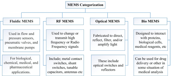
Categorisatie van MEMS-apparaten
Voor de meeste van de huidige technologieën zijn MEMS-sensoren een nieuw voorkeursgebied voor veel praktische toepassingen, van consumentenelektronica tot de luchtvaartindustrie. Het belangrijkste kenmerk van MEMS is de mogelijkheid om effectief te communiceren met elektrische componenten in halfgeleiderchips, en de sensorindustrie heeft een revolutie teweeggebracht met behulp van MEMS-technologie door elektronische functies en mechanische acties te combineren [34], ze hebben normaal gesproken een laag stroomverbruik en een hoge gevoeligheid vanwege tot het kleine formaat [35, 36]. Op MEMS gebaseerde sensorapparaten hebben veel voordelen waardoor ze een belangrijke rol spelen in verschillende toepassingen. Deze voordelen omvatten lage kosten vanwege de mogelijkheid van arrayfabricage [37, 38], laag stroomverbruik [37,38,39,40] en kleine afmetingen [38,39,40,41,42]. MEMS heeft ook veel andere voordelen, zoals lichtgewicht, hoge resolutie, stabiele prestaties en gemakkelijke integratie met andere apparaten en systemen. Micromechanische naar micromechanische apparaatreducties zijn op verschillende gebieden verbeterd, bijvoorbeeld traagheidssensoren, chemische sensoren, inkjetprinters, gyroscopen, satellieten, RF-communicatie, smartphones, druksensoren, versnellingsmeters, biomedische instrumentatie [43], militaire toepassingen, beweging en kracht sensoren [44]. Bovendien spelen de lage kosten en eenvoud van het fabricageproces een cruciale rol bij commerciële productie [45].
Volgens het werkingsprincipe kunnen sensorapparaten worden onderverdeeld in twee categorieën op basis van het werkingsprincipe:statische en dynamische modus van de werking van het apparaat [46, 47]. Wanneer de MEMS-apparaten zijn gebaseerd op de statische modus, wordt er geen frequentiesignaal opgenomen. Ook wordt de straal afgebogen als gevolg van de oppervlakte-adsorptiemassa, wat tijdelijke resultaten van spanning en structurele vervorming zal veroorzaken. Het kan optisch worden gedetecteerd of gedetecteerd door veranderingen in de piëzoweerstand. Er ontstaat een zekere chemische binding op het oppervlak van het apparaat en de interne nanomechanica kan de MEMS-straaldetectie verbuigen [46]. In de dynamische modus, om optimale prestaties van het apparaat te krijgen, moet een mechanische resonantiefrequentie worden gestimuleerd. De maximale amplitude die door het vibrerende systeem kan worden bereikt en een maximale resonantie in een specifiek systeem kan opwekken, wordt een resonantiefrequentie genoemd. Waarbij de resonantiefrequentie wordt beïnvloed door twee hoofdparameters:de veerconstante van de straal en zijn effectieve massa, en zal veranderen volgens deze parameters. Dit is het werkingsprincipe om de verandering in resonantiefrequentie als detectiemiddel te gebruiken. De kwaliteitsfactor moet hoog zijn om de gewenste gevoeligheid en resolutie te verkrijgen [48, 49]. Het is noodzakelijk om deze mechanismen te begrijpen en te vergelijken, aangezien ze de basis vormen voor de werking van de MEMS-apparaten en de detectie van het uitgangssignaal.
Actuatietechnieken
De activeringstechniek is een term die wordt gegeven aan het mechanisme dat de invoerenergie omzet in een microstructuurbeweging. Er zijn verschillende principes en benaderingen voor het aansturen van MEMS-apparaten [7, 50,51,52,53,54,55], waarvan de belangrijkste zijn:elektrostatische aansturing [56,57,58,59,60,61,62, 63,64], elektrothermische activering [4, 44, 65,66,67,68], elektromagnetische activering [7, 69] en piëzo-elektrische activering [48, 70] (Fig. 2). Complementaire metaal-oxide-halfgeleider CMOS-MEMS-sensorapparaten zijn ontworpen om te werken met ofwel elektrostatische activering met behulp van parallelle plaatcondensatoren of elektrothermische activering met behulp van een microverwarmer. Aan de andere kant zijn PolyMUMPs- en MetalMUMPs-sensorapparaten ontworpen om elektrothermische activering te gebruiken met behulp van ingebouwde microverwarmers [71].
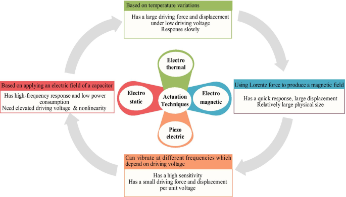
Bedieningstechnieken van op MEMS gebaseerd sensorapparaat
Op MEMS gebaseerde apparaten kunnen worden geactiveerd door een sinusoïdale kracht F . uit te oefenen (t ), via een van de bovengenoemde bedieningsmethoden. Vergelijking (1) wordt gebruikt om de algemene bewegingsvergelijking te vinden sinds M is de totale massa van de bovenplaat, b is de dempingscoëfficiënt, k veerconstante van de flexibele balk,
$$M\ddot{\gamma } + b\dot{\gamma } + k\gamma =F(t)$$ (1)waar F vertegenwoordigt de amplitude van de externe drijvende kracht in de z -richting, \(\ddot{\gamma }\)\(\ddot{\upgamma }\), \(\dot{\upgamma }\) \(\dot{\gamma }\) en γ zijn respectievelijk de versnelling, snelheid en verplaatsing van de massa.
Elektrostatische actuatoren zijn vrij wijdverbreid; ze hebben een snelle responstijd en een laag stroomverbruik [72]. Aan de andere kant zijn de actuatoren die gebruikmaken van het elektrothermische principe populair; ze hebben een grote aandrijfkracht en verplaatsing onder lage stuurspanning. Elektromagnetische actuatoren hebben enkele voordelen als een snelle respons, grote verplaatsing. De actuatoren die het piëzo-elektrische principe gebruiken, hebben een hoge gevoeligheid, hoewel een kleine aandrijfkracht en verplaatsing per eenheidsspanning. Daarom is een goed begrip van het principe dat plaatsvindt essentieel om een krachtig apparaat te verkrijgen met een van deze activeringsbenaderingen.
Elektrostatische aandrijving
De belangrijkste bron van de elektrostatische activering is het elektrische veld van de condensator, en het is afhankelijk van de aantrekkingskracht tussen twee parallelle platen met tegengestelde ladingen [12]. Elektrostatische activering is gebaseerd op de wet van Coulomb die de wederzijdse kracht weergeeft tussen twee ladingen met een bepaalde afstand die wordt gegenereerd tussen vaste en beweegbare platen. Elektrostatische activering wordt beschouwd als een van de meest populaire mechanismen voor het bedienen van MEMS-apparaten. Ze hebben een eenvoudig ontwerp, snelle responstijd, gemakkelijke fabricage en een laag stroomverbruik. De niet-lineariteit en de verhoogde waarde van de stuurspanning is echter de belangrijkste kwestie van dit type actuator [72]. Sommige soorten elektrostatische aandrijving moeten zorgvuldig worden overwogen bij het bestuderen van MEMS onder elektrostatische aandrijving. De meest voorkomende vormen zijn gebaseerd op ofwel een condensator bestaande uit twee eenvoudige parallelle platen of een kam-aandrijfstructuur bestaande uit meerdere al dan niet in elkaar grijpende vingers [72, 73]. Een conventionele methode [74] is de parallelle plaatbediening waarbij de bovenste bewegende plaat een bepaalde polariteit heeft en de onderste vaste plaat een tegengestelde polariteit (Fig. 3). De verplaatsing en trilling van de bewegende plaat zijn afhankelijk van het spanningsverschil tussen de twee platen. Wanneer de polariteit van de ladingen vergelijkbaar is, zal er een afstotende verplaatsing zijn tussen de vaste en bewegende platen, maar wanneer de twee platen verschillende ladingen hebben, zal de bewegende plaat worden aangetrokken door de vaste plaat. Activering vindt plaats wanneer het type lading op de bewegende plaat periodiek wordt gewijzigd [50, 56, 74].

Parallelle plaatcondensator voor de elektrostatische aansturing [75]
Instabiliteit bij het intrekken is een van de belangrijkste problemen wanneer de parallelle plaat elektrostatisch wordt aangedreven, omdat de vaste plaat zich net onder de microstraal bevindt en de statische wrijving ervoor zorgt dat het apparaat instort [74, 76]. Comb-drives-actuators bestaan uit twee kamsets van in elkaar grijpende vingerstructuren (Fig. 4). Ze worden gewoonlijk in dezelfde evenwijdige plaat als het substraat geplaatst waar een kamvinger is vastgemaakt en de andere is verbonden met flexibele structuren (bijvoorbeeld veren) om naar en weg van de vaste plaat te bewegen [72]. Wanneer een verschillende spanning wordt aangelegd tussen de beweegbare kam en de vaste kamvingers, trekt de elektrostatische kracht van de randvelden de twee kammen naar elkaar toe door een vaste externe sinusoïdale kracht. Gewoonlijk zijn condensatoren met parallelle platen sterker dan actuatoren met kamaandrijving per oppervlakte-eenheid, omdat ze een grotere overlapcapaciteit hebben tussen de vaste en bewegende plaat van de actuator. Ontwerpers geven er echter de voorkeur aan om actuatoren te kammen vanwege deze twee hoofdredenen:het produceert een grotere verplaatsing (er zijn enkele tientallen micrometers beschikbaar) en de kracht is relatief niet gerelateerd aan de verplaatsing. Over het algemeen heeft elektrostatische activering brede toepassingen gevonden in micromechanische actuator [77], biosensortoepassing [56], vochtigheidsdetectie [57], deeltjes- en massadetectietoepassingen [50, 78], MEMS-nanopositioneringssysteem [58], RF MEMS-schakelaartoepassingen [ 13, 79], closed-loop ruis van MEMS-oscillatoren [60], navigatie (automobiel Global Positioning System GPS) [62, 80], gyroscopen [81], biomarkerdetectie in uitgeademde adem [82] en massagevoelige gassensoren [ 63]. Bovendien werd ook het theoretische model van elektrostatisch geactiveerde en capacitieve op CMOS-MEMS gebaseerde sensorapparatuur voor niet-invasieve screening van diabetes gerapporteerd. Waarbij diabetische screening werd uitgevoerd door detectie van acetondamp in uitgeademde adem (EB), waarbij chitosanpolymeer werd gebruikt als detectiemateriaal. Specifiek werd een geoptimaliseerde gevoeligheid gerapporteerd over 0,042, 0,066, 0,13, 0,18 en 0,26 pm/ppm [83].
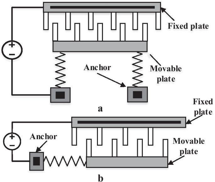
Schema van de elektrostatische comb-drive configuraties [84, 85], a longitudinale interdigitated kam actuator; b dwarse aandrijving
Om een MEMS-apparaat in resonantietoestand of trillingsmodus te brengen, moet een alternatieve aandrijving worden uitgevoerd door een wisselspanning aan te leggen tussen de twee platen van stator en rotor. De standaard rijmodi worden weergegeven als volgt [49]:eenvoudige alternatieve spanning (V 1 sinωt) , wisselspanning met een dc-bias (V 0 + V 1 sinωt) en push-pull rijden (Fig. 5). Push-pull-aandrijving wordt over het algemeen als de beste oplossing beschouwd omdat structurele krachten op beide zijden van de rotor kunnen worden uitgeoefend. Push-pull is een ideale aandrijving die geschikt is voor het comb-drive-schema [49].
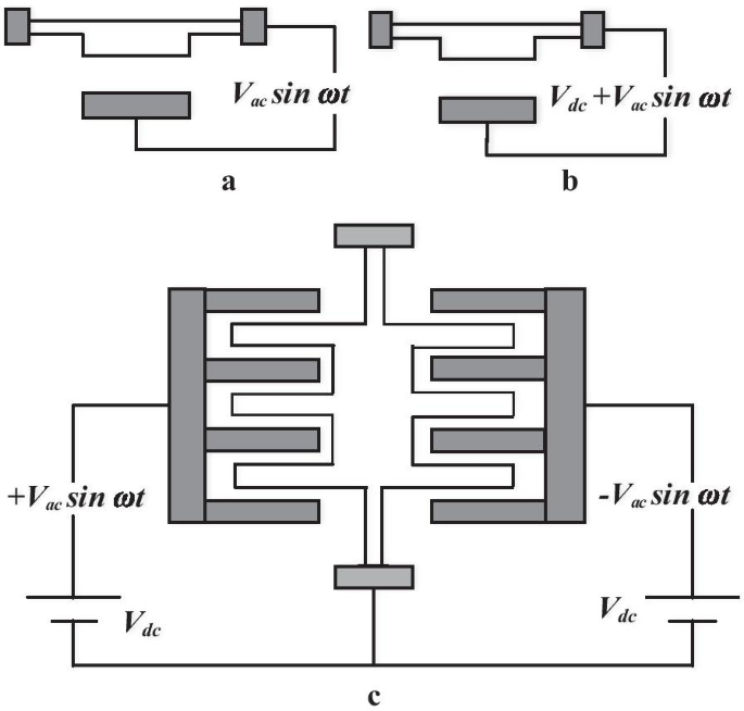
Kam aandrijfresonator a Eenvoudig aansturen van alternatieve spanning, b wisselspanning met een dc-bias, en c push-pull rijschema [86]
Elektrothermische aandrijving
Elektrothermische technieken worden meestal gebruikt in MEMS-drives, terwijl ze zelden worden gebruikt in detectietoepassingen [72]. De elektrothermische techniek is in wezen geschikt voor een flexibele configuratie om beweging te genereren met de gewenste verplaatsing. Aangedreven wordt geleid door een wisselstroom die wordt aangelegd via de klemmen van de ingebouwde microverwarmer als gevolg van de thermische kracht die het gevolg is als reactie op het temperatuurverschil van de verschillende lagen [66]. De microverwarmer is gemaakt van componenten van verschillende materiaallagen en werkt bij verhoogde temperaturen. Wanneer de wisselstroom wordt toegepast, stijgt de temperatuur van het apparaat; als gevolg van de mismatch in de thermische uitzettingscoëfficiënt (CTE) van de verschillende materialen, zet het materiaal uit, waardoor thermische spanning ontstaat die ervoor zorgt dat het apparaat buigt [72]. Aan de andere kant kan de koelingsbenadering toegankelijk zijn via geleiding naar het substraat en convectie naar de omringende lucht (of vloeistof).
Deze temperatuurveranderingen beïnvloeden het apparaat op twee manieren, zoals gerapporteerd in [44, 87]:(1) dimensionale veranderingen in het apparaat of spanningen die in het apparaat worden gegenereerd, en (2) materiaaleigenschappen van het apparaat variëren met de temperatuur. De huidige techniek moet worden verdicht tot de microheater. Microheater genereert de gewenste warmte doordat een specifieke stroom op de weerstand wordt toegepast, wat kan resulteren in een lage vermogensdissipatie en een snelle responstijd. De elektrothermische kracht kan worden beschreven door (2) [88].
$$F_{th} =\alpha_{T} AE(T - T_{0} )$$ (2)waar α T is de CTE,E is de jonge modulus van de bundel, A is het dwarsdoorsnedeoppervlak van de balk, T is de eindtemperatuur, en T 0 is de begintemperatuur vóór verwarming. Er zijn verschillende materialen gebruikt in ontwerpen voor microverwarmers. Om bijvoorbeeld de beste prestaties, nauwkeurigheid, wijdverbreide temperatuurbereik en stabiliteit te bereiken, zijn platina en goud de beste beslissingen voor de microverwarmer [89]. Ze zijn echter duur [90]. Het gebruik van microverwarmers in MEMS-sensoren heeft een ingebouwde temperatuursensor nodig om de geproduceerde warmte om te zetten in bruikbare output. Voor temperatuursensoren is platina beschikbaar in het temperatuurbereik − 200 C tot 800 ºC en nikkel is beschikbaar in het temperatuurbereik − 100 tot 260 C [90]. Volgens rapporten is aluminium ook een goed materiaal voor temperatuurmeting [91]. Afbeelding 6 toont de algemene mechanismen van elektrothermische activering, waaronder U-Beam Actuator (warme/koude arm), bimorfe actuator (Bi-materiaalactuator) en knikactuatoren (V-Beam Actuator of shuttle-balken).
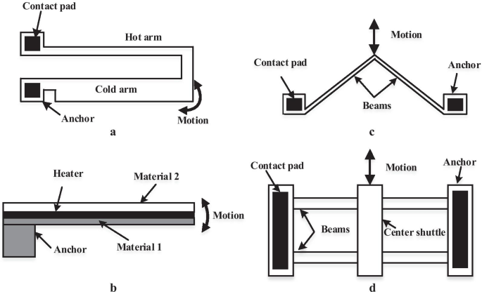
Schema van de elektrothermische aandrijving a U-Beam Actuator (warm/koud arm), b bimorfe actuator (bi-materiaal actuator), c en d knikactuators (V-Beam Actuator en pendelbalken) [67, 92]
U-vormige aandrijvingen zijn ook bekend als warme/koude armen, waarbij de aandrijving is gemaakt van een smalle arm (warm), een brede arm (koud) anker en contactvlakken [67, 92]. Het wordt voornamelijk gebruikt voor in-plane of horizontale incitatie in vergelijking met het substraat. Het werkingsprincipe van deze techniek hangt af van het toepassen van een differentiële spanning over de contactvlakken, stroom vloeit door de armen en de hete armen (hogere weerstand) warmen meer stroomdichtheid op dan de koude arm (lagere weerstand). Een smallere hete arm is daarom heter en zal meer uitzetten dan een dikkere arm. De hete arm produceert grote thermische spanningen. Deze differentiële spanning tussen beide armen zorgt ervoor dat het hele apparaat afbuigt.
Een bimorfe actuator, ook wel bi-materiaal genoemd, bestaat uit twee verschillende thermisch uitzettende materialen die aan elkaar zijn gehecht. In tegenstelling tot de eerste twee aandrijvers, wordt de bimorfe aandrijver [93] doorgaans gebruikt voor activering buiten het vlak. Naarmate de stroom door de straal gaat, neemt de temperatuur van het materiaal toe. Deze temperatuur zorgt voor een grotere uitzetting in het ene materiaal dan in het andere omdat het een andere thermische uitzettingscoëfficiënt heeft, wat resulteert in thermische spanning en buiging van het apparaat.
Thermische knikactuators bestaan uit een V-balk of shuttle-balk [94], ankers en contactvlakken, die ook voornamelijk worden gebruikt voor in-plane of laterale bediening. Terwijl de stroom door de straal stroomt, veroorzaakt de stijging van de straaltemperatuur thermische uitzetting als gevolg van de Joule-verwarming die optreedt, die de neiging heeft om uit te zetten en de shuttle te verplaatsen of de centrale straal van het apparaat naar voren te duwen in de eenvoudigste en minst resistente richting.
In de echte implementatie worden de meeste MEMS-apparaten met thermische activering getrild op frequenties die dicht bij de natuurlijke frequentie liggen, dus het is essentieel om de natuurlijke frequentie van de apparaten te berekenen. De elektrothermische technologie komt vaker voor vanwege de grote drijvende kracht en verplaatsingen op basis van thermische uitzetting van de sleeplaagmaterialen onder een zeer lage excitatiespanning, wat niet kan worden bereikt door welke andere strategieën dan ook wanneer vergelijkbare metingen worden gebruikt [85, 95]. Elektrothermische activering vertoont meerdere voordelen, zoals grote verplaatsing [95], gemakkelijke fabricage [72], grote kracht en relatief lage aangelegde spanning [52]. Integendeel, ze vereisen een grote hoeveelheid stroom en een laagspanningsversterker. Bovendien verbruikt hij veel stroom door de Joule-verwarming. Nog een beperking is een gevoeligheid voor de omgevingstemperatuur. Ten slotte kan de opwindende temperatuur en hitte die toenemen als gevolg van elektrothermische activering verschillende nadelen veroorzaken voor de naburige elektronica, samen met de verpakkingsfase van het systeem [72].
Talloze soorten elektrothermische aandrijving zijn ontwikkeld en bestudeerd; Warme/koude arm [96,97,98], bi-materiaal of bimorf [98, 99] en thermische knikactuator [98, 100]. Reference [101], heeft de micro-cantilever-vibraties onderzocht onder thermische activering met behulp van de bimorph-actuator. Referentie [102], heeft een gestructureerde procedure voorgesteld voor polysilicium microring thermische activering (RTA) vervaardigd met behulp van de MUMPs-processen. Een micro-cantilever op basis van de thermische bediening is ontworpen. Ze gingen ervan uit dat het systeem zich in vacuüm of vloeibare (gas) vloeistof bevindt en stelden een analytische oplossing voor [103]. Dennis et al. [44] fabriceerde een (CMOS-MEMS) systeem met ingebouwde microverwarmers die bij relatief hoge temperaturen (40-80 °C) werken om vochtigheidsniveaus te meten met behulp van titaniumdioxide (TiO2 ) nanodeeltjes als detectiemateriaal. De sensor werd in dynamische modus bediend met behulp van een elektrothermische activering en een uitgangssignaal beoordeeld met behulp van een piëzoresistieve (PZR) -sensor aangesloten op het Wheatstone-brugcircuit. De uitgangsspanning van de vochtigheidssensor stijgt van 0,585 tot 30,580 mV als de vochtigheid stijgt van 35% RH tot 95% RH. The sensitivity of the humidity sensor increases linearly from 0.102 mV/% RH to 0.501 mV/% RH with an increase in the temperature from 40 to 80 °C and a maximum hysteresis of 0.87% RH is found at a relative humidity of 80%. In a further notable contribution, Almur et al. [104] modelled a MetalMUMPs acetone vapour sensing system based on electrothermal actuation and capacitive sensing. The output voltage change was found to increase linearly with increasing the acetone vapor concentration from 100 to 500 ppm with a concentration sensitivity of 0.65 mV/ppm. Due to the thick nickel layer of the MetalMUMPs technology used the device has very high mass (4.7 × 10 –8 kg) and low mass sensitivity (0.118 MHz/pg).
Electromagnetic Actuation
The electromagnetic operation has long been utilized in the sensing and driving of the large scaling applications (such as loudspeakers). This technique demands electricity to stimulate the magnetic effect. It uses the electromagnetic force (also can be called Lorentz force after the Dutch physicist Hendrik A. Lorentz 1895) to produce a magnetic field to the resonator by applying an alternating current on the coil or inductor integrated into the resonator (Fig. 7). Lorentz Force is defined as the force generated on a point charge as a result of the combined electric and magnetic forces on the charge [72]. Electromagnetic actuation has also been utilized as a guide to other actuation techniques, for example, electrostatic [33] and electrothermal [34]. In this technique, when a conductor conveying an electric current I can be applied to an external magnetic field B , this will induce a Lorentz force F L as stated by (3) [72].
$$\vec{F}_{L} =L\vec{I} \times \vec{B}$$ (3)waar L indicted to the conductor length and × refers to the cross product operation. The current in the conductive element located within the magnetic field generates an electromagnetic force in a direction perpendicular to the current and the magnetic field. This force has a directly proportional to the current, magnetic flux density and length of the microbeam. Because of the interaction generated by the current between the magnet and the magnetic field, a mechanical displacement on the microbeam will be generated as a result of the applied current to the micro-coil. For example, electromagnetic actuation has been used to stimulate microbeam when being exposed to an external magnetic field by flowing current through the microbeam, as seen in Fig. 7a. Similarly, as alternating current flows through the device on the microbeam, this approach can be used to excite the out-of-plane resonator (Fig. 7b). Lorentz forces of equal value and opposite directions are produced if the coil is deposited on a structure of the microbeam. The opposite directions of the current flowing through the different parts of the coil correspond to these forces. Such forces balance one another out. Figure 7c, however, can induce a net motion that is used to actuate the microbeam [72].
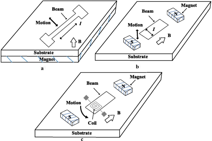
Schematic of the electromagnetic actuation using Lorentz forces a in-plane actuator, b en c out-of-plane actuator [72]
The electromagnetic technique involves many merits over the other kind of actuation techniques. The main advantages of the electromagnetic actuation include the large displacement without the influence of the nonlinear effect [105], lower voltages due to they based on current rather than voltage-driven [7], in addition, they have a high reproducibility rate, they also have more features like rapid response, high accuracy, and the merit for controlling easily. For MEMS applications, the electromagnetic technique is the best choice to achieve maximum driving force for device size ratio [106]. However, they still suffering from some drawbacks due to using the huge current resulting in high power consumption, also their fabrication is complicated (normally be in need of inductive parts to produce magnetic flux also the possibility of including the manufacture of coils, and the deposition of a magnetic material) [7]. This fact combined with constructive difficulties has limited magnetic actuation applications. However, there are successful application examples in the literature as it may exist in MEMS switches devices [7], Optical switches, and micro scanners [69], gyroscopes [107], or relays [108]. Many researches are also based on magnetic actuation [109]. The magnetic microsensors utilizing the commercial 0.35 μm CMOS process has been investigated [110]. In a further contribution, Barba et al. [111] designed an electromagnetically actuated MEMS cantilevers proposed in order to minimize parasitic phenomena using Boron-doped silicon. In another seminal work, an electromagnetic and Piezoelectric actuated and piezoresistive sensed CMOS- MEMS device has been modelled for humidity sensing using ZnO NRs (6 μm/chitosan SAMs) as a sensing material [83]. The sensitivity was found to be 83.3 ppm [112].
Piezoelectric Actuation
Piezoelectric effect indicates the capability of a particular material to produce an electrical voltage in response to applied the mechanical stress. Piezoelectricity was discovered by the Curie brothers in 1880, and 'Piezo' meaning is coming from the Greek word that is mean 'press' or 'push'. A piezoelectric actuator defined as transducers that converts an applied potential into a mechanical movement or strain based on the piezoelectric influence [72]. Piezoelectric materials like quartz, zinc oxide, lead zirconate titanate (piezoelectric ceramic material PZT), and polyvinylidene difluoride (PVDF) are commonly used in sensor and actuator applications on a macro scale as well as in MEMS applications in recent years, but the sensing is limited due to their lack of a DC response [49]. Piezoelectric materials act electrically as insulators and required to be placed between two conductive electrodes so as to gather charge or to apply an electric-field (using an interdigitated electrode or sandwich structure) [113].
In MEMS devices, the basic principle of the piezoelectric actuation method is based on using a thin piezoelectric layer that is deposited as a part of the MEMS beam between flexible (Fig. 8). When a voltage is applied to the piezoelectric layer, the piezoelectric material expands according to the polarization of the applied voltage, which causes an axial bending across the length of the flexible beam [114].
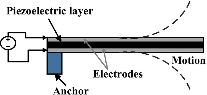
Schematic of the piezoelectric actuator [72]
In general, piezoelectric actuators exhibit a lot of advantages such as high output force, good operating bandwidth, very compact size, lightweight, low power consumption, and fast response [114, 115]. Their characteristics are well known and have been used for decades. Most first sensors use piezoelectric actuation and are still in use today. However, small displacements of actuators are a major drawback, and their high-temperature sensitivity [72], nonlinear working area and hysteresis limit their wide range of applications [49]. Piezoelectric materials are very brittle. They can seldom be utilized alone but are often connected to a flexible structure for actuation and sensing applications. There are several works based on piezoelectric actuation [2, 48, 114, 116] studied the prospective to use a piezoresistive microcantilever for environment application, particularly for humidity sensing. Mahdavi et al. [117] proposed a new class of accurate dew point measurements taking advantage of thin-film Piezoelectric-on-Silicon (TPoS) resonators using ZnO NRs (6 μm/chitosan SAMs). The sensitivity was found to be 16.9–83.3 ppm at the range of response time of 46 s/167 s. sensitivity to mass loading based on piezoelectric excitation is investigated for chemical sensing [118, 119] reported piezoelectric transduction of flexural-mode silicon resonators to achieve efficient temperature compensation. The resonance gas sensor using piezoelectric MEMS for defence applications was reported [120].
Actuation Techniques Discussion
Different types of MEMS actuators require different drive electronics. As per mentioned in this article, there are different principles and approaches to actuate MEMS devices. The most important of which include:electrostatic actuation, electrothermal actuation, electromagnetic actuation, and piezoelectric actuation. Electrostatic actuators are a traditional field and considered one of the most popular mechanisms for actuating MEMS devices. They have a simple design, fast response time, ease of fabrication and low power consumption. However, the non-linearity and the elevated value of the driving voltage is the major matter of this type of actuator. Electrothermal actuators provide very low resistance to their drive sources and require high currents rather than high voltages to move them. High voltage amplifiers are not particularly suitable for use in electrothermal MEMS actuators. Instead, a low voltage and high current signal source are required. Of course, this can also work if the output current of the high voltage amplifier is large enough to drive the electrothermal actuator, but it is not a particularly energy-efficient or cost-effective solution. For MEMS applications, electromagnetic technology is the best choice to achieve maximum driving force per device size ratio. However, they still suffering from some drawbacks due to using the huge current that results in high power consumption, also their fabrication is complicated (normally be in need of inductive parts to produce magnetic flux also the possibility of including the manufacture of coils, and the deposition of a magnetic material). Piezoelectric actuators also required high voltage amplifiers, but since they are typically used for resonance, the drive requirements in terms of driving voltage are typically lower than those required for other actuators. The recent research of MEMS-based sensor devices which can be actuated using the four basic actuation techniques that have been used during the last few years for many applications, as shown in Table 2. It can be clearly observed that there is a rising development pattern in the field of micro-assembly and micromanipulation for MEMS-based sensor devices that have been categorized based on actuation techniques. Nowadays, a wide range of applications has been identified for MEMS-based sensor devices that provide high sensitivity and resolution. The sensing systems are getting more robust and reliable due to the integration configuration.
Sensing Mechanisms for the Output Signal
The sensing mechanism is used to sense the output of the MEMS devices. The basic of the sensing technique is based on the use of a polymer deposited on the sensing layer of the device to absorb a particular chemical that creates a variation in the stress, mass, electrical or mechanical characteristics of the beam. To estimate the change in the mass, the resonant frequency of the device can be measured based on the detected mass increment that is one of its parameters. Then again, when the polymer absorbs the mass, piezoresistor that is situated on the surface of the sensing element can be used to estimate the mass of the beam. Another method of detecting suspected chemicals is to use thermocouples to measure temperature changes caused by the heat generated by the polymer absorbing analyte [49].
To sense the output of these MEMS devices methods such as piezoresistive, capacitive or optical mechanisms are used (Fig. 9) [123]. Different sensing mechanisms have different advantages and disadvantages at the same time.
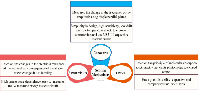
Sensing mechanisms of MEMS-based sensor devices
For instance, optical sensing has good feasibility; however, it is very expensive to implement compared to capacitive and piezoresistive techniques [124]. Capacitive and piezoresistive techniques are the common methods used to sense the output signal. CMOS- MEMS device was designed to encompass both piezoresistive and capacitive sensing techniques due to the features of 0.35 µm CMOS technology used to design it. In contrast, PolyMUMPs and MetalMUMPs devices were designed to use only capacitive sensing techniques.
Piezoresistive Sensing
Piezoresistive is a common sensing principle used in MEMS devices. Essentially, the principle of piezoresistive materials is based on the resistance change when their strain changes in response to applied stress. This change can be observed in the electrical resistance of the material of the device as a consequence of a surface-stress change due to bending. The resistance value of the piezoresistor with the resistivity ρ of a resistor, length of l and cross-section area A is given by (4) [29].
$$R =\frac{\rho l}{A}$$ (4)The change ΔR in resistance is proportional to the applied strain can be defined in (5) [29, 125].
$$\Delta R =G\varepsilon R$$ (5)where G is the gauge factor work as a proportionality constant of the piezoresistor, ε is the strain in the material, and R is the piezoresistor resistance. A piezoresistive element behaves differently towards longitudinal and transverse strain component presented by [29]. According to (5), the resistance of a piezoresistor can vary owing to the changes of the geometry (length and cross-section) or in the property of the material (resistivity). Piezoresistive detection depends on the difference in resistivity of material when stress is applied. In a piezoresistive material, the change of resistivity because of the application of stress has a much greater effect on the resistance than the change in resistivity because of a change in the geometry (sensors rely on the change of resistance owing to the geometry are so-called strain gauges) [72]. (Fig. 10) shows different resistor orientations and external force loading directions [88].
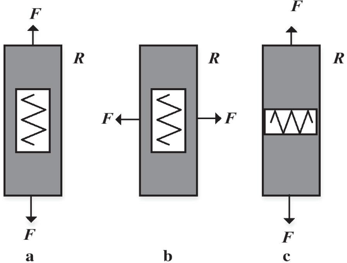
een Longitudinal piezoresistance dominates, b en c transverse piezoresistance dominates presented [29]
The main drawback of this sensing mechanism is the solid temperature reliance of resistivity. To limit this impact, normally, a collecting of four piezoresistive designed is utilized to shape a Wheatstone bridge. This limits the temperature reliance [72]. Furthermore, the small changes in the electric signal generated from gauges are translated and gauged as voltages utilizing this Wheatstone bridge [49]. Wheatstone bridge utilizes four resistors arranged in the bridge of the four arms (Fig. 11). Based on the quantity of these active resistors (acting as a transducer), single active bridge (single transducer), half active bridge (double transducers), and the full active bridge (quadruple transducers) of the bridge of Wheatstone might be utilized as reported [72]. The single active bridge as well called Quarter Bridge that utilizes just a single active component which changes because of a physical ambient, for example, pressure, power, temperature, while the remnants of that resistors will be passive and so on. MEMS systems have been used as temperature, calorimeter, and in combination with the Wheatstone bridge, sensors allow the base fluctuations. Thermal bridge system is one of the best-known sensing platforms among MEMS. In the AC-driven Wheatstone bridge configuration (Fig. 11b), researchers have utilized the resistance-based thermometry to analyse temperature changes with micro-Kelvin resolution. In an overview, the right half of the bridge comprises a sensing resistor on the lower branch with associated resistance on the top, while the left side is defined as the matching one. Fixed resistors with a relatively low resistance coefficient of temperature are used with resistance values, which was chosen to enhance stability and resolution based on the previous study [126].
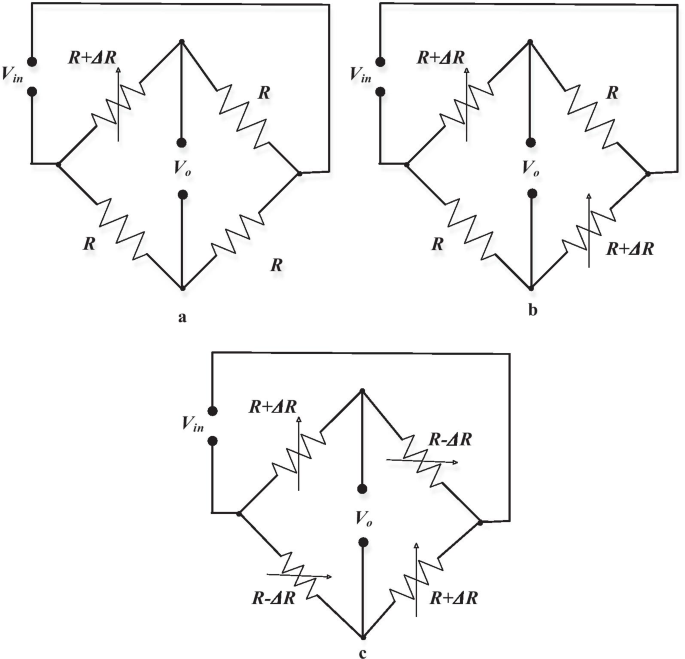
Schematic types of a Wheatstone bridge, a quarter bridge, b half-bridge, and c full-bridge configurations [72]
Silicon piezoresistor and polysilicon patches are generally utilized in MEMS sensors. The resistivity of silicon relies upon its strategy for doping. N-type doped with silicon is less sensitive than p-type. This raises limitation to the fabrications. In this situation, an in-plane transversal and in-plane longitudinal will be the most significant elements [72]. For semiconductor materials like silicon, the longitudinal and transverse gauge factors owing to geometry change are quite tiny compared to their values due to resistivity change, hereafter the change in geometry can be ignored, and the longitudinal and transverse gauge factors due to only the resistivity change are found using (6) and (7), respectively [127].
$$G_{L} =\pi_{L} E$$ (6) $$G_{T} =\pi_{T} E$$ (7)waar E is Young's modulus of the piezoresistive material. π L and π T are the longitudinal and transverse piezoresistance coefficients, respectively, for arbitrarily oriented polysilicon grains, and their values are given in Table 3 [19].
Currently, the piezoresistive effect has been utilized as a bio-or chemical detection [48], humidity sensing purpose [4], switch applications [59], biomarker detection in exhaled breath [82], micro scanners [69], pressure sensing [128], and mass-sensitive gas sensors [63]. Zope et al. [117] developed a resistively sensed thermally-driven piezo resonator composed predominantly of CMOS material for mass sensing applications. whereas mass sensitivity of 24.96 kHz/ng was reported. The extracted mass resolution of 16.3 fg have also been observed, hence showing great potential to serve as an aerosol sensor).
Capacitive Sensing
The capacitive sensing mechanism is based on measuring the changes of the capacitance between the stator and rotor fingers or between the fixed plate and movable plate [88]. Capacitive sensing is the main dominant method for micromachined applications due to its compatibility with all the fabrication approaches and stiffness [129, 130]. Capacitive sensing has many attractive features include high sensitivity, low power consumption, simplicity in design, low drift and low-temperature dependency. Furthermore, the measurement of the output signal can be easily fabricated on the PolyMUMPs die using capacitive sensing. Only a single parallel plate can be used to capacitively sensed the variations in the natural frequency or amplitude of the MEMS devices (such as a CMOS-MEMS device and a PolyMUMPs device) or by applying a comb finger (such as a MetalMUMPs device).
For CMOS-MEMS device and PolyMUMPs devices, when there is no actuation (Fig. 12a), the initial static sensed capacitance (Cs0 ) between the lower fixed plate and the movable top plate is calculated using (8) [19].
$$C_{s0} =\frac{{\varepsilon A_{s} }}{{z_{0} }}$$ (8)where ℇ is the relative permittivity of the dielectrics, As is the area of the sensed plates and z0 is the gap between the fixed and movable plates. When the movable plate is displaced by z (Fig. 12b) the initial gap changes, and hence the capacitance will change too, and it is found by (9).
$$C_{s} (z) =\frac{{\varepsilon A_{s} }}{{z_{0} - z}} =C_{s0} \frac{{z_{0} }}{{z_{0} - z}}$$ (9)
Parallel plate capacitor showing a initial condition and b after displacing the movable plate [19]
At the same time, for the MetalMUMPs devices, the output can be detected capacitively by utilizing the differential comb fingers design. As appeared in Fig. 13, there are two arrangements of fixed comb fingers to have the differential capacitance.
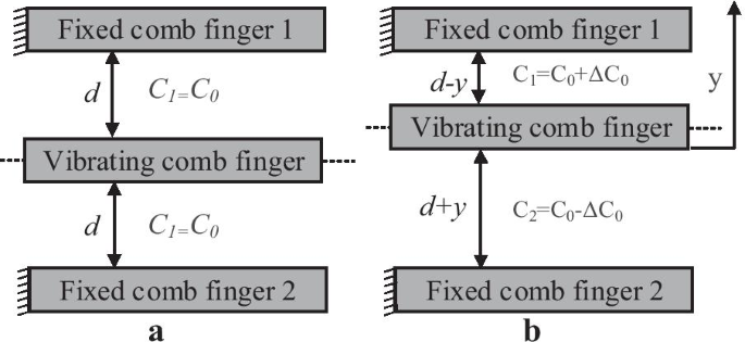
Comb fingers configuration for MetalMUMPs device showing a the initial condition and b the displacement of the vibrating comb finger [19]
For the initial condition, when the device is not actuated (Fig. 13a), the static detected capacitance C0 for every set of vibrating-fixed fingers could be calculated by (10).
$$C_{0} =n\frac{{\varepsilon l_{f} w_{f} }}{d}$$ (10)where l f and w f are length and width of the overlapping area of the vibrating and fixed comb fingers, respectively. d is the gap between the fixed and vibrating comb fingers and n is the number of the vibrating comb fingers. When the device is moved by y toward the fixed comb finger one as appeared by (Fig. 13b), the capacitances C 1 en C 2 will be changed and relying upon that shift, and their values can be calculated using (11) and (12), respectively.
$$C_{1} (x) =n\frac{{\varepsilon l_{f} w}}{d - y}$$ (11) $$C_{2} (x) =n\frac{{\varepsilon l_{f} w}}{d + y}$$ (12)The output signal of the device will be measured as a voltage due to change in the sensing capacitance upon actuation using MS3110 capacitive readout circuit that translates the change in capacitance to the output voltage change in response to the temperature of the microheaters. Nowadays, capacitive effects are used in MEMS resonators [60], biosensor application [56], humidity sensor [57], diabetes screening [66], Navigation (automobile Global Positioning System (GPS)) [62], a low noise accelerometer [131], and RF MEMS capacitive switches [132].
Optical Detection
Optical sensing mechanism depends on detecting the changes in the transmitted light compared to the received light. The detection of compound species by spectral transmission strategy is broadly acknowledged. Optical sensors are notable due to their selectivity since it does not rely upon any chemical reaction or any chemical catalyst activities. Air pollutants identification is recognized by using the characteristics of the optical species (for example, absorption, refractive index, Raman scattering, fluorescence, and reflection). Optical sensors utilize emission and absorption measurements primarily through different technologies such as Fourier transform infrared spectroscopy (FTIR), surface plasma resonance (SPR), differential optical absorption spectroscopy (DOAS), laser diode absorption spectroscopy (LDAS), cavity ring-down spectroscopy (CRDS), non-dispersive infrared (NDIR) spectroscopy, light detection and ranging (LIDAR), UV fluorescence and chemiluminescence for the sensing of air pollutants in air specimens. Normally, the light will be cross through, modified or reflected by some space having the relevant medium (Fig. 14). Beer–Lambert law can be used to govern the optical detection of the air pollutants as per the following:
$$I =I_{0} *e^{ - \alpha l}$$ (13)where the transmitted light through the specimen is I , ik 0 is the received light, α represent the absorptivity, l represents the length of the path.
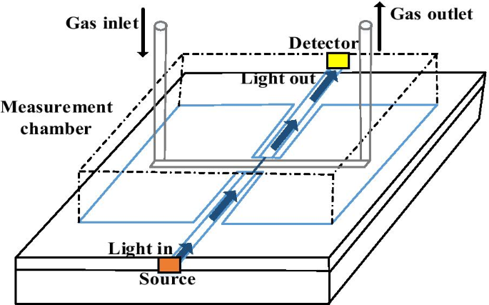
Schematic representation of an optical MEMS sensor [133]
However, the majority of the applications for optical MEMS are in communications; there are various uses in different fields [134]. The literature covered numerous attempts to introduce the optical detection of air pollutants. A few of these sensors are used to recognize chemicals. This displays the multifunctional part of these sensors. Infrared spectrometry is a case of a technique that can be utilized for optical sensing [135]. In a further notable contribution, Huang and co-workers have also demonstrated [136] the simulation of an integrated optical MEMS accelerometer. The effective simulation results have demonstrated as follows:a resonance frequency of 562.85 Hz, a mechanical sensitivity of 781.64 nm/g, an optical system sensitivity of 1.23, a resolution of 1.037 µg, and low cross-sensitivity. The proposed accelerometer can be used for improvements in MEMS inertial navigation devices. Another model is the Fabry–Perot optical sensor [137]. Basically stated, the principles of this sensor are based on bringing gas into a chamber and a short time later going light through the chamber. Due to changes in the substance piece, the light experiencing will be not exactly equivalent to without the gas. This light is broke down, and from the results, confirmation can be made about the sort of gas being tested. The fruitful testing of an optical MEMS sensor for the location of catechol was reported [133]. The absorbance measurement of catechol oxidation was performed by blue light (472 nm) attached through a MEMS device. The light was transmitted from a free-space blue laser working in persistent wave mode and is focused on a multimode fibre utilizing manually arranged to organize. Received light was coupled by means of the optical fibre to a USB connected spectrophotometer which assisted computerized information collection utilizing the software.
Sensing Mechanisms Discussion
In view of different working principles, the above-mentioned sensing mechanisms can be divided into three types, namely piezoresistive, capacitive and optical mechanisms. There are benefits and drawbacks for different sensing mechanisms at the same time. For instance, optical sensing has good feasibility; however, it is very expensive to implement compared to capacitive and piezoresistive techniques. As a result, piezoresistive and capacitive techniques are the common methods used to sense the output signal. Any small change in the stress could be detected using a piezoresistive technique. A main disadvantage of the piezoresistive sensing technique is the high-temperature reliance of resistivity. In Table 3, present the recent work and progress (last 5 years), including actuation and sensing mechanisms, sensing materials, fabrication technology and application. The miniaturized microchip presented (in Table 4) can be utilized for gas and humidity sensing, human health screening, inertial navigation with good repeatability, high resolution, high sensitivity, and rapid response. In addition, MEMS sensors have been proven to be an effective medium for sensors combined with on-chip electronic circuitry. It can therefore function not only as a portable sensor chip but can also be linked as part of the Internet of Things (IoT) network to achieve real-time and remote high-sensitivity moisture tracking.
Discussion
Recent developments are about new technologies that can harvest energy from the environment, because sustainable self-sufficient micro/nano power sources are an emerging field of nanoenergy, which involves nanomaterials and nanotechnology when harvesting energy for powering micro/nano systems [139]. The triboelectric charge is produced only on the surface dependent on the physical friction between two separate materials. The triboelectric nanogenerator (TENG) is a device that transforms mechanical energy into contact separation or relative sliding between two materials with opposite polarities. TENG based on the coupling effect between triboelectricity and electrostatic induction in which it’s updated progress and potential applications as new energy technology and as self-powered active sensors. The suggested approach uses biomechanical energy transfer to electricity from human activity [139, 140]. Amongst them is a successful study has been investigated for the conversion to wearable energy from portable biometric devices and self-powered sensors based on triboelectricity (i.e. the charge produced on the touch surface) [141,142,143,144].
-
To decrease power consumption during operation, sensors of woken up or almost zero-power supplement need to proposed and investigated, meaning that these sensors do not have any energy consumption. With these components of MEMS, MEMS sensors can work for a long period or can be operated in a self-powered.
-
Looking forward to the future-oriented sensors, sensors with flexibility have become hot topics of the recent research in the latest years owing to their versatility and great prospective in health/human beings applications. Flexible sensors are often used in combination with wearable sensors to have their unique advantages. More than just utilizing the flexible sensor such as a wearable electronic for observation functions, they can be even utilized as a human–machine interface for achieving higher requirements. With the enhancement of the quality of human life, wearable devices and human–machine interfaces have been recognized as important directions for developing sensors of the future with sufficient flexibility and versatile sensing capabilities. Wearable electronic devices can be simply integrated with the human body to extend our perception capabilities. Sensor functions of wearable electronic devices include, but are not limited to, force, strain, electrophysiology, heart rate monitors, temperature, fitness trackers, etc. With the service of various devices among different anatomical positions, development of many applications of the human body sensor can be facilitated from hospital care to fitness and wellness tracking, human–machine interfaces and recognition and assessment of cognitive states.
-
Meanwhile, by combining MEMS sensor with artificial intelligence (AI), the next generation of sensors will provide clear evolutionary impact and help humans interact with other things in various applications circumstances. Moreover, the quick improvement of the modern community has observed the expanding association among people with machines, demanding huge intelligent human–machine devices. Around a huge data and hypersensitive detecting, MEMS sensor utilizing a machine learning strategy dramatically stimulates the enlargement of the coming generation smart sensing system. This interactive system with next-generation sensor provides consumers with a more comprehensive experience. It can be used for many practical applications, such as simulation of sports training, entertainment, medical rehabilitation and so on.
Conclusions and Future Trends
It is well recognized that MEMS-based sensors play a key role in the field of miniaturization and electronic microcircuits. It is necessary to understand and compare these mechanisms since they are the basis of the MEMS-based devices operation and output signal detection. This article reviews several popular actuation and sensing mechanisms related to MEMS devices that have emerged over the past few decades. This article introduced a descriptive overview to the advancement of the actuation and sensing mechanisms of the MEMS-based sensor devices. The up-to-date trends and the restrictions while giving a valuable perception into the field of emerging actuation and sensing technologies. A comprehensive discussion was presented, underlining the significance of the actuation and sensing mechanisms, its structure, working principles, classification, fabrication and applications. Proper understanding of the actuating and sensing mechanisms for the MEMS-based sensor devices play a vital role in their selection and effective application in various innovative technologies. In addition, the proper selection of actuating and sensing techniques in MEMS sensors based on the desired application such as sensitivity, resonant frequency, input\output voltage, temperature etc., will lead to fast-commercialization and better product stability.
In order to perform various tasks for different applications such as industry and electronic equipment, different MEMS devices with different structures collaborated with diverse actuation and sensing mechanisms will arise in true-life. Moreover, MEMS devices will not only be used for simple tasks, but also for more jobs that are complex. At the same time, MEMS devices will have greater freedom and can meet the needs of a variety of applications. However, in order to pursue higher accuracy and miniaturization, the complexity of MEMS device design will continue to increase. In addition, MEMS products have a close relationship with the market. It can be predicted that MEMS devices will realize more functions, miniaturization and low cost, which is a huge challenge for other products. Therefore, in the next few years, MEMS fabrication approaches will develop to a higher level to meet market demand. With the advancement of MEMS device fabrication processes, unique hardware makers will seek after shorter fabrication cycles and quicker fabrication speeds.
One of the central areas of the future trend in this area is reliability research and improvement methods. Moreover, new materials and cost-effective of the fabrication techniques will provide important opportunities for development. It has been demonstrated that the design capability is not limited to standard principles and can improve qualitative performance. Despite MEMS advantages, few challenges still exist in the following aspects.
-
The traditional MOS thin films by MEMS techniques often show poor sensitivity to target gases due to the compact surface structure and low crystallinity.
-
In recent studies, it have tried to integrate high-performance MOS nanomaterials onto microheaters. Still, it is difficult to control and cast the slurry-based MOS nanomaterials onto the suspending heating area of microheaters. However, the low yield and large device-to-device deviation hamper the sensor fabrication on a large scale.
-
It is also complicated to improve the adhesion between microheaters and sensing materials to get stable parameters, especially at high temperatures > 350 °C which results in decreased sensing performance and low stability [14, 145].
-
Fabricating sensing films with high sensitivity using MEMS compatible methods is an urgent goal.
-
Towards a new era, different challenges can face MEMS-based sensors in terms of power supply and intelligence during the operation, such as the challenges of the flexibility of wearable applications, the friendly interactive capabilities of human–machine interface applications, and analysis of the huge data.
Beschikbaarheid van gegevens en materialen
Niet van toepassing.
Afkortingen
- MEMS:
-
Microelectromechanical system
- pH:
-
Potential hydrogen
- ICs:
-
Integrated circuits
- LOD:
-
Detectielimiet
- MUMPs:
-
Multi-user MEMS
- MST:
-
Microsystems technology
- RF:
-
Radio frequency
- CMOS:
-
Complementaire metaaloxide halfgeleider
- CTE:
-
The coefficient of thermal expansion
- AC:
-
Wisselstroom
- DC:
-
Gelijkstroom
- RTA:
-
Ring thermal actuation
- PVDF:
-
Polyvinylidene difluoride
- GPS:
-
Global positioning system
- FTIR:
-
Fourier-transformatie infraroodspectroscopie
- SPR:
-
Surface plasma resonance
- DOAS:
-
Differential optical absorption spectroscopy
- LDAS:
-
Laser diode absorption spectroscopy
- CRDS:
-
Cavity ring down spectroscopy
- NDIR:
-
Non-dispersive infrared
- LIDAR:
-
Light detection and ranging
- IDE:
-
Interdigitated electrodes
- PZR:
-
Piezoresistive
- EFS:
-
Electrostatic field sensor
- AI:
-
Artificial intelligence
Nanomaterialen
- Virtuele sensorwerking en zijn toepassingen
- Bezettingssensor werkt en zijn toepassingen
- Deursensor werkt en zijn toepassingen
- Inductieve sensorwerking en toepassingen
- IoT-sensorwerking en zijn toepassingen
- Meet temperaturen met een 1-draads DS18B20-sensor en Raspberry Pi
- Sensoren begrijpen
- Draagbare gassensor voor gezondheids- en milieubewaking
- Executive Roundtable:Sensing en IIoT
- Op grafiet gebaseerde sensor voor draagbare medische apparaten
- Lab-on-chip stroom- en temperatuursensor


