


Combinatielogica met altijd
Het verilog always-blok kan worden gebruikt voor zowel sequentiële als combinatorische logica. Een paar ontwerpvoorbeelden werden getoond met een assign uitspraak in een vorig artikel. Dezelfde reeks ontwerpen zal vervolgens worden onderzocht met behulp van een always blok.
Voorbeeld #1:Eenvoudige combinatorische logica
De onderstaande code implementeert een eenvoudige digitale combinatorische logica met een uitgangssignaal genaamd z van het type reg dat wordt bijgewerkt wanneer een van de signalen in de gevoeligheidslijst zijn waarde verandert. De gevoeligheidslijst wordt aangegeven tussen haakjes na de @ telefoniste.
module combo ( input a, b, c, d, e,
output reg z);
always @ ( a or b or c or d or e) begin
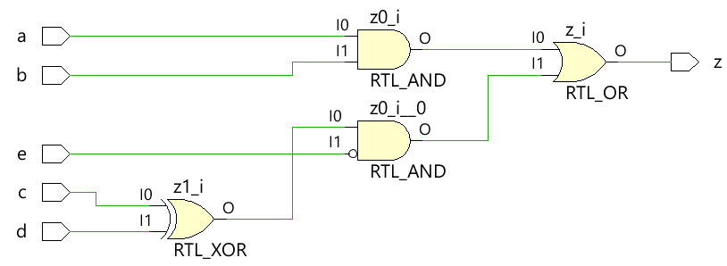
z = ((a & b) | (c ^ d) & ~e);
end
endmodule
De module combo wordt uitgewerkt in het volgende hardwareschema met behulp van synthesetools en kan worden gezien dat de combinatorische logica wordt geïmplementeerd met digitale poorten.
 Gebruik blokkeringstoewijzingen bij het modelleren van combinatorische logica met een altijd blok
Testbank
De testbench is een platform voor het simuleren van het ontwerp om ervoor te zorgen dat het ontwerp zich gedraagt zoals verwacht. Alle combinaties van ingangen worden naar de ontwerpmodule gestuurd met behulp van een for lus met een vertragingsverklaring van 10 tijdseenheden, zodat de nieuwe waarde na enige tijd op de ingangen wordt toegepast.
module tb;
	// Declare testbench variables
  reg a, b, c, d, e;
  wire z;
  integer i;

  // Instantiate the design and connect design inputs/outputs with
  // testbench variables
  combo u0 ( .a(a), .b(b), .c(c), .d(d), .e(e), .z(z));

  initial begin
  	// At the beginning of time, initialize all inputs of the design
  	// to a known value, in this case we have chosen it to be 0.
    a <= 0;
    b <= 0;
    c <= 0;
    d <= 0;
    e <= 0;

    // Use a $monitor task to print any change in the signal to
    // simulation console
    $monitor ("a=%0b b=%0b c=%0b d=%0b e=%0b z=%0b",
              a, b, c, d, e, z);

    // Because there are 5 inputs, there can be 32 different input combinations
    // So use an iterator "i" to increment from 0 to 32 and assign the value
    // to testbench variables so that it drives the design inputs
    for (i = 0; i < 32; i = i + 1) begin
      {a, b, c, d, e} = i;
      #10;
    end
  end
endmodule
Simulatielogboek ncsim> run a=0 b=0 c=0 d=0 e=0 z=0 a=0 b=0 c=0 d=0 e=1 z=0 a=0 b=0 c=0 d=1 e=0 z=1 a=0 b=0 c=0 d=1 e=1 z=0 a=0 b=0 c=1 d=0 e=0 z=1 a=0 b=0 c=1 d=0 e=1 z=0 a=0 b=0 c=1 d=1 e=0 z=0 a=0 b=0 c=1 d=1 e=1 z=0 a=0 b=1 c=0 d=0 e=0 z=0 a=0 b=1 c=0 d=0 e=1 z=0 a=0 b=1 c=0 d=1 e=0 z=1 a=0 b=1 c=0 d=1 e=1 z=0 a=0 b=1 c=1 d=0 e=0 z=1 a=0 b=1 c=1 d=0 e=1 z=0 a=0 b=1 c=1 d=1 e=0 z=0 a=0 b=1 c=1 d=1 e=1 z=0 a=1 b=0 c=0 d=0 e=0 z=0 a=1 b=0 c=0 d=0 e=1 z=0 a=1 b=0 c=0 d=1 e=0 z=1 a=1 b=0 c=0 d=1 e=1 z=0 a=1 b=0 c=1 d=0 e=0 z=1 a=1 b=0 c=1 d=0 e=1 z=0 a=1 b=0 c=1 d=1 e=0 z=0 a=1 b=0 c=1 d=1 e=1 z=0 a=1 b=1 c=0 d=0 e=0 z=1 a=1 b=1 c=0 d=0 e=1 z=1 a=1 b=1 c=0 d=1 e=0 z=1 a=1 b=1 c=0 d=1 e=1 z=1 a=1 b=1 c=1 d=0 e=0 z=1 a=1 b=1 c=1 d=0 e=1 z=1 a=1 b=1 c=1 d=1 e=0 z=1 a=1 b=1 c=1 d=1 e=1 z=1 ncsim: *W,RNQUIE: Simulation is complete.
Merk op dat beide methoden, assign en always , worden geïmplementeerd in dezelfde hardwarelogica.
Voorbeeld #2:Halve opteller
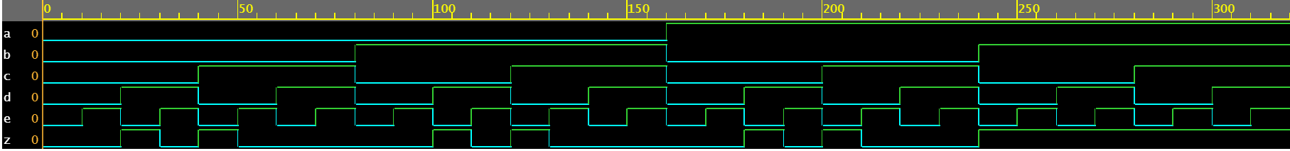
De halve optelmodule accepteert twee scalaire ingangen a en b en gebruikt combinatorische logica om de uitgangssignalen sum en carry bit cout toe te wijzen. De som wordt aangestuurd door een XOR tussen a en b, terwijl de carry-bit wordt verkregen door een AND tussen de twee ingangen.
module ha ( input 	a, b,
						output	sum, cout);

	always @ (a or b) begin
		{cout, sum} = a + b;
	end

endmodule
Testbank
module tb;
	// Declare testbench variables
  reg a, b;
  wire sum, cout;
  integer i;

  // Instantiate the design and connect design inputs/outputs with
  // testbench variables
  ha u0 ( .a(a), .b(b), .sum(sum), .cout(cout));

  initial begin
  	// At the beginning of time, initialize all inputs of the design
  	// to a known value, in this case we have chosen it to be 0.
    a <= 0;
    b <= 0;

    // Use a $monitor task to print any change in the signal to
    // simulation console
    $monitor("a=%0b b=%0b sum=%0b cout=%0b", a, b, sum, cout);

    // Because there are only 2 inputs, there can be 4 different input combinations
    // So use an iterator "i" to increment from 0 to 4 and assign the value
    // to testbench variables so that it drives the design inputs
    for (i = 0; i < 4; i = i + 1) begin
      {a, b} = i;
      #10;
    end
  end
endmodule
Simulatielogboek ncsim> run a=0 b=0 sum=0 cout=0 a=0 b=1 sum=1 cout=0 a=1 b=0 sum=1 cout=0 a=1 b=1 sum=0 cout=1 ncsim: *W,RNQUIE: Simulation is complete.

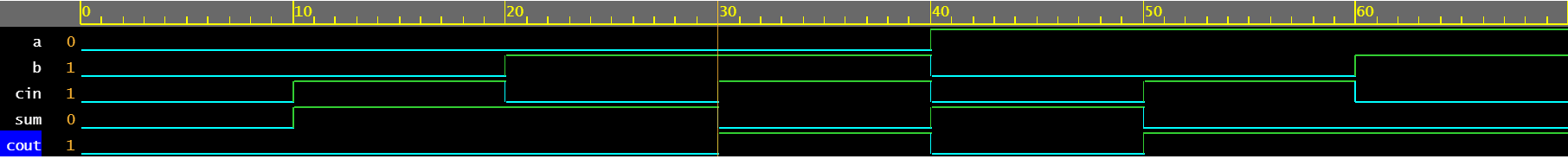
Voorbeeld #3:Volledige opteller
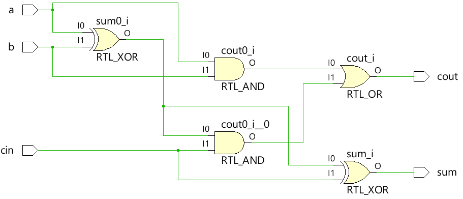
Een altijd-blok kan worden gebruikt om het gedrag van een volledige opteller te beschrijven om de outputs som en cout aan te sturen.
module fa (	input 	a, b, cin,
			output reg	sum, cout);

  always @ (a or b or cin) begin
    {cout, sum} = a + b + cin;
  end

endmodule
Testbank
module tb;
  reg a, b, cin;
  wire sum, cout;
  integer i;

  fa u0 ( .a(a), .b(b), .cin(cin), .sum(sum), .cout(cout));

  initial begin
    a <= 0;
    b <= 0;

    $monitor("a=%0b b=%0b cin=%0b cout=%0b sum=%0b", a, b, cin, cout, sum);

    for (i = 0; i < 8; i = i + 1) begin
      {a, b, cin} = i;
      #10;
    end
  end
endmodule
Simulatielogboek ncsim> run a=0 b=0 cin=0 cout=0 sum=0 a=0 b=0 cin=1 cout=0 sum=1 a=0 b=1 cin=0 cout=0 sum=1 a=0 b=1 cin=1 cout=1 sum=0 a=1 b=0 cin=0 cout=0 sum=1 a=1 b=0 cin=1 cout=1 sum=0 a=1 b=1 cin=0 cout=1 sum=0 a=1 b=1 cin=1 cout=1 sum=1 ncsim: *W,RNQUIE: Simulation is complete.
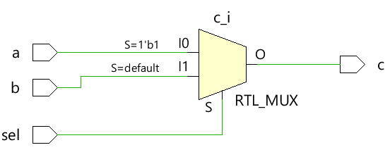
Voorbeeld #4:2x1 multiplexer
De eenvoudige 2x1 multiplexer gebruikt een ternaire operator om te beslissen welke ingang moet worden toegewezen aan de uitgang c. Als sel 1 is, wordt de output aangestuurd door a en als sel 0 is, wordt de output aangestuurd door b.
module mux_2x1 (input 	a, b, sel,
				output 	reg c);


  always @ ( a or b or sel) begin
	c = sel ? a : b;
  end
endmodule
Testbank
module tb;
	// Declare testbench variables
  reg a, b, sel;
  wire c;
  integer i;

  // Instantiate the design and connect design inputs/outputs with
  // testbench variables
  mux_2x1 u0 ( .a(a), .b(b), .sel(sel), .c(c));

  initial begin
  	// At the beginning of time, initialize all inputs of the design
  	// to a known value, in this case we have chosen it to be 0.
    a <= 0;
    b <= 0;
    sel <= 0;

    $monitor("a=%0b b=%0b sel=%0b c=%0b", a, b, sel, c);

    for (i = 0; i < 3; i = i + 1) begin
      {a, b, sel} = i;
      #10;
    end
  end
endmodule
Simulatielogboek ncsim> run a=0 b=0 sel=0 c=0 a=0 b=0 sel=1 c=0 a=0 b=1 sel=0 c=1 ncsim: *W,RNQUIE: Simulation is complete.

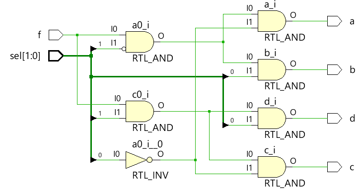
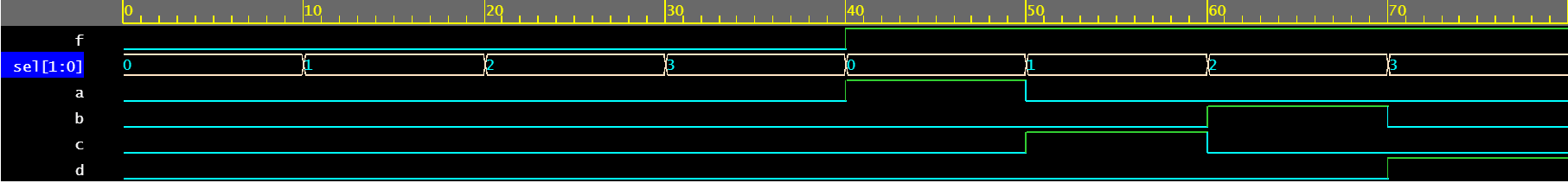
Voorbeeld #5:1x4 demultiplexer
De demultiplexer gebruikt een combinatie van sel- en f-ingangen om de verschillende uitgangssignalen aan te sturen. Elk uitgangssignaal is van het type reg en gebruikt in een always blok dat wordt bijgewerkt op basis van wijzigingen in de signalen in de gevoeligheidslijst.
module demux_1x4 (	input 				f,
										input [1:0]	 	sel,
										output reg		a, b, c, d);

  always @ ( f or sel) begin
    a = f & ~sel[1] & ~sel[0];
    b = f &  sel[1] & ~sel[0];
    c = f & ~sel[1] &  sel[0];
    d = f &  sel[1] &  sel[0];
  end

endmodule
Testbank
module tb;
	// Declare testbench variables
  reg f;
  reg [1:0] sel;
  wire a, b, c, d;
  integer i;

  // Instantiate the design and connect design inputs/outputs with
  // testbench variables
  demux_1x4 u0 ( .f(f), .sel(sel), .a(a), .b(b), .c(c), .d(d));

  // At the beginning of time, initialize all inputs of the design
  // to a known value, in this case we have chosen it to be 0.
  initial begin
    f <= 0;
    sel <= 0;

    $monitor("f=%0b sel=%0b a=%0b b=%0b c=%0b d=%0b", f, sel, a, b, c, d);

    // Because there are 3 inputs, there can be 8 different input combinations
    // So use an iterator "i" to increment from 0 to 8 and assign the value
    // to testbench variables so that it drives the design inputs
    for (i = 0; i < 8; i = i + 1) begin
      {f, sel} = i;
      #10;
    end
  end
endmodule
Simulatielogboek ncsim> run f=0 sel=0 a=0 b=0 c=0 d=0 f=0 sel=1 a=0 b=0 c=0 d=0 f=0 sel=10 a=0 b=0 c=0 d=0 f=0 sel=11 a=0 b=0 c=0 d=0 f=1 sel=0 a=1 b=0 c=0 d=0 f=1 sel=1 a=0 b=0 c=1 d=0 f=1 sel=10 a=0 b=1 c=0 d=0 f=1 sel=11 a=0 b=0 c=0 d=1 ncsim: *W,RNQUIE: Simulation is complete.
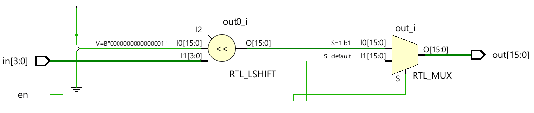
Voorbeeld #6:4x16-decoder
module dec_3x8 ( 	input 			en,
					input 	[3:0] 	in,
					output  reg [15:0] 	out);

  always @ (en or in) begin
    out = en ? 1 << in: 0;
  end

endmodule
Testbank
module tb;
  reg en;
  reg [3:0] in;
  wire [15:0] out;
  integer i;

  dec_3x8 u0 ( .en(en), .in(in), .out(out));

  initial begin
    en <= 0;
    in <= 0;

    $monitor("en=%0b in=0x%0h out=0x%0h", en, in, out);

    for (i = 0; i < 32; i = i + 1) begin
      {en, in} = i;
      #10;
    end
  end
endmodule
Simulatielogboek ncsim> run en=0 in=0x0 out=0x0 en=0 in=0x1 out=0x0 en=0 in=0x2 out=0x0 en=0 in=0x3 out=0x0 en=0 in=0x4 out=0x0 en=0 in=0x5 out=0x0 en=0 in=0x6 out=0x0 en=0 in=0x7 out=0x0 en=0 in=0x8 out=0x0 en=0 in=0x9 out=0x0 en=0 in=0xa out=0x0 en=0 in=0xb out=0x0 en=0 in=0xc out=0x0 en=0 in=0xd out=0x0 en=0 in=0xe out=0x0 en=0 in=0xf out=0x0 en=1 in=0x0 out=0x1 en=1 in=0x1 out=0x2 en=1 in=0x2 out=0x4 en=1 in=0x3 out=0x8 en=1 in=0x4 out=0x10 en=1 in=0x5 out=0x20 en=1 in=0x6 out=0x40 en=1 in=0x7 out=0x80 en=1 in=0x8 out=0x100 en=1 in=0x9 out=0x200 en=1 in=0xa out=0x400 en=1 in=0xb out=0x800 en=1 in=0xc out=0x1000 en=1 in=0xd out=0x2000 en=1 in=0xe out=0x4000 en=1 in=0xf out=0x8000 ncsim: *W,RNQUIE: Simulation is complete.

Verilog
- Tutorial - Combinatie- en sequentiële code schrijven
- Circuit met een schakelaar
- Geïntegreerde circuits
- Programmable Logic Controllers (PLC)
- Inleiding tot Booleaanse algebra
- Rekenen met wetenschappelijke notatie
- Vraag en antwoord met een Industry 4.0 Solution Architect
- Temperatuur bewaken met Raspberry Pi
- Voorbeelden van Verilog Gate-niveaus
- Verilog Tijdnotatie
- Altijd een gladde afwerking met Okamoto-slijpmachines