



Draagbare Remote Surveillance Camera Robot
Onderdelen en benodigdheden
| SparkFun Arduino Pro Mini 328 – 5V/16MHz | 1 |
| Band + DC-motor met tandwielkast + beugel | 1 |
| SparkFun Dual H-Bridge Motor Driver L298 | 1 |
| Raspberry Pi 3 Model B | 1 |
| Raspberry Pi Camera Module | 1 |
Benodigde tools
- USB-naar-serieel FTDI adapter (FT232RL)
- Arduino IDE
- Boormachine
- Fijne zaag
- Schroevendraaiers
- Solderbout
- Draadknipper
Over dit project
Een ambitieus project dat robotbouw, geavanceerde Linux-configuratie (Raspberry Pi), Android-app ontwikkeling en remote besturing combineert. Je leert veel, zelfs als je alleen delen nabouwt.
Kernconcepten:
- Platforms: Arduino, Raspberry Pi, Android
- Elektronica: H-brug, transistor voor zware last, IR-sensoren
- Linux: Docker, Docker Compose, systemd-services, video-streaming (uv4l)
- Programmeren: Android (Java/Kotlin), Python, Arduino C++, seriële communicatie, MQTT
Stap 1: Benodigdheden
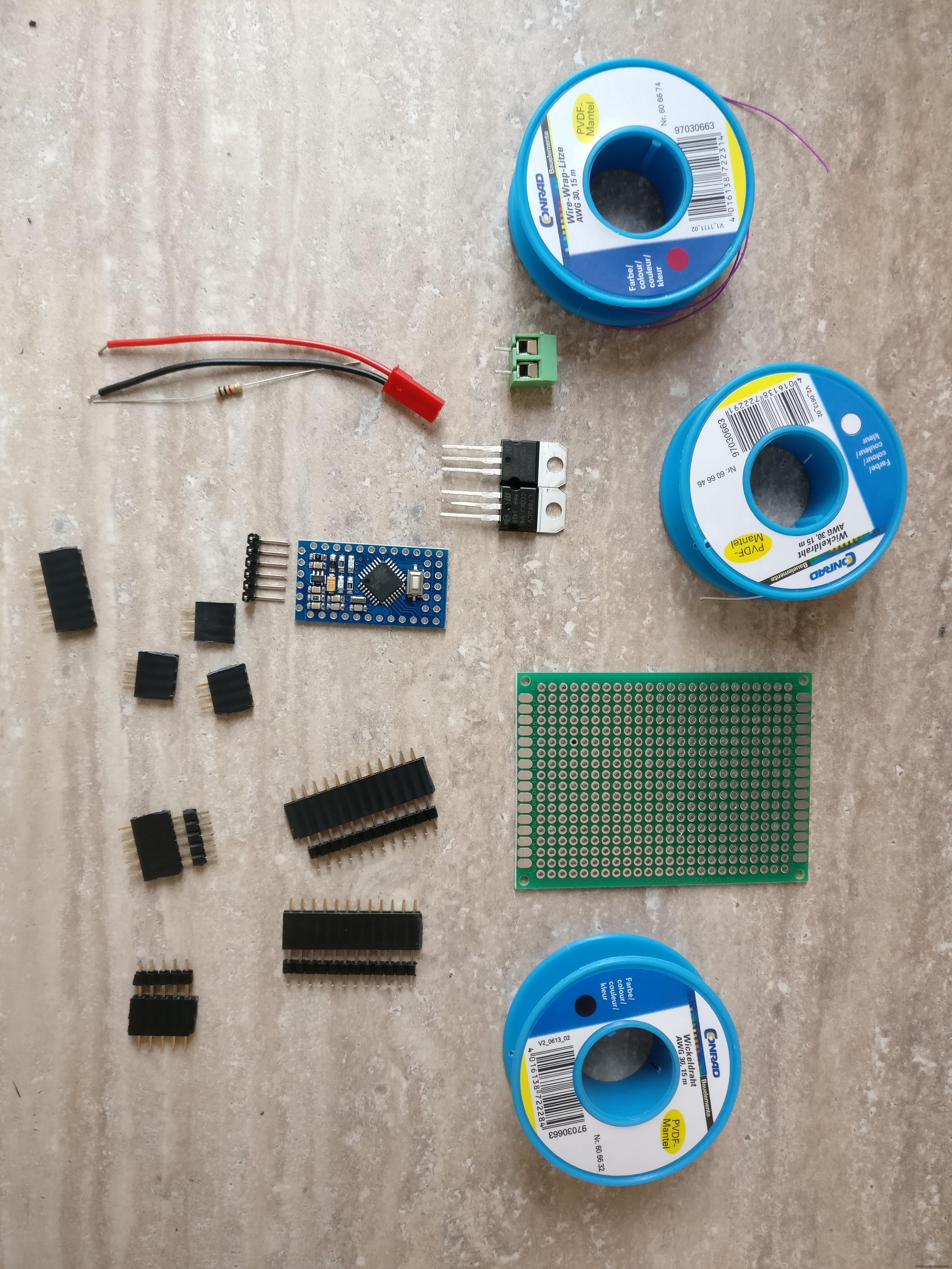
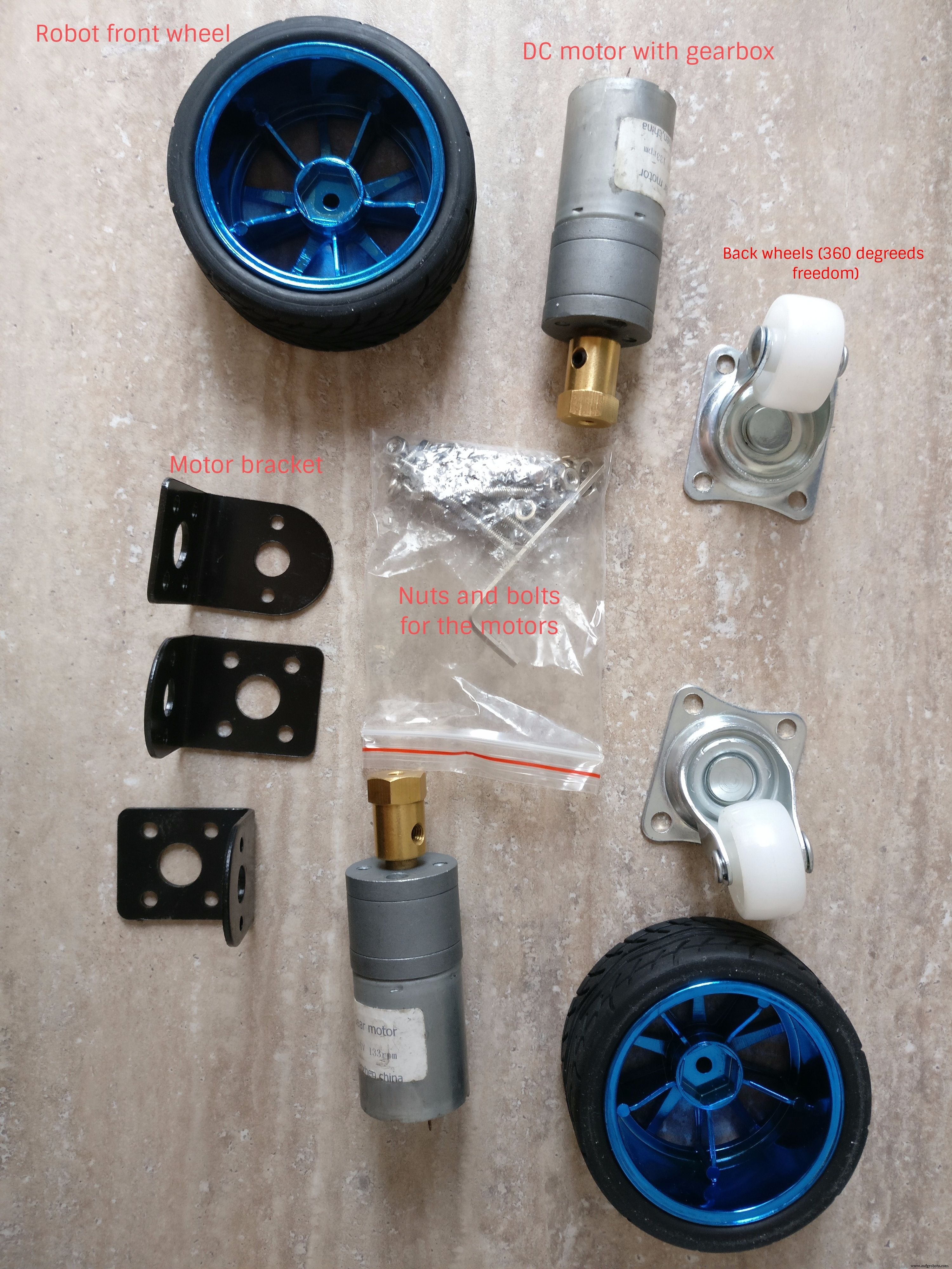
Onderdelenlijst:
- Plexiglasplaat (basis & top)
- Kunststofplaat (alternatief voor plexiglas)
- Lijm
- Band + DC-motor met tandwielkast + beugel, kleine bouten/moeren, zeshoekse afstandsbusjes
- 2× omnidirectionele wieltjes (achter)
- Kleine LED-zaklamp (wordt hoofdlicht)
- Arduino Pro Mini 328P
- 2× IR-obstakelsensoren
- PCB (printplaat)
- NPN-transistor (voor hoofdlicht)
- L7805CV 5V-regulator
- L298 H-brug
- Weerstand 220 Ω
- Male USB-A connector
- Male Micro-USB connector
- Diverse draden
- 3,3V regulator (voor Pi ↔ Arduino communicatie)
- Male & female PCB-connectors
- Aan/uit schakelaar
- XT-60 female LiPo-connector
- 2S 1300 mAh LiPo-batterij met XT-60
- 5V powerbank
- Raspberry Pi 3 + camera + geheugenkaart (≥4GB) + behuizing
Vaardigheden: solderen, basis Arduino, Linux service-configuratie.
Stap 2: Robot-platform bouwen
Specificaties:
- Aandrijving op voorwielen (2 aparte DC-motoren)
- Achterwielen 360° vrij draaiend
- Sturing via differentiële snelheid (geen apart stuurmechanisme), kan op eigen as draaien
- Bovenlichtjes
- Ruimte voor elektronica, batterijen, Pi-behuizing met camera
- Enkele cm grondvrijheid
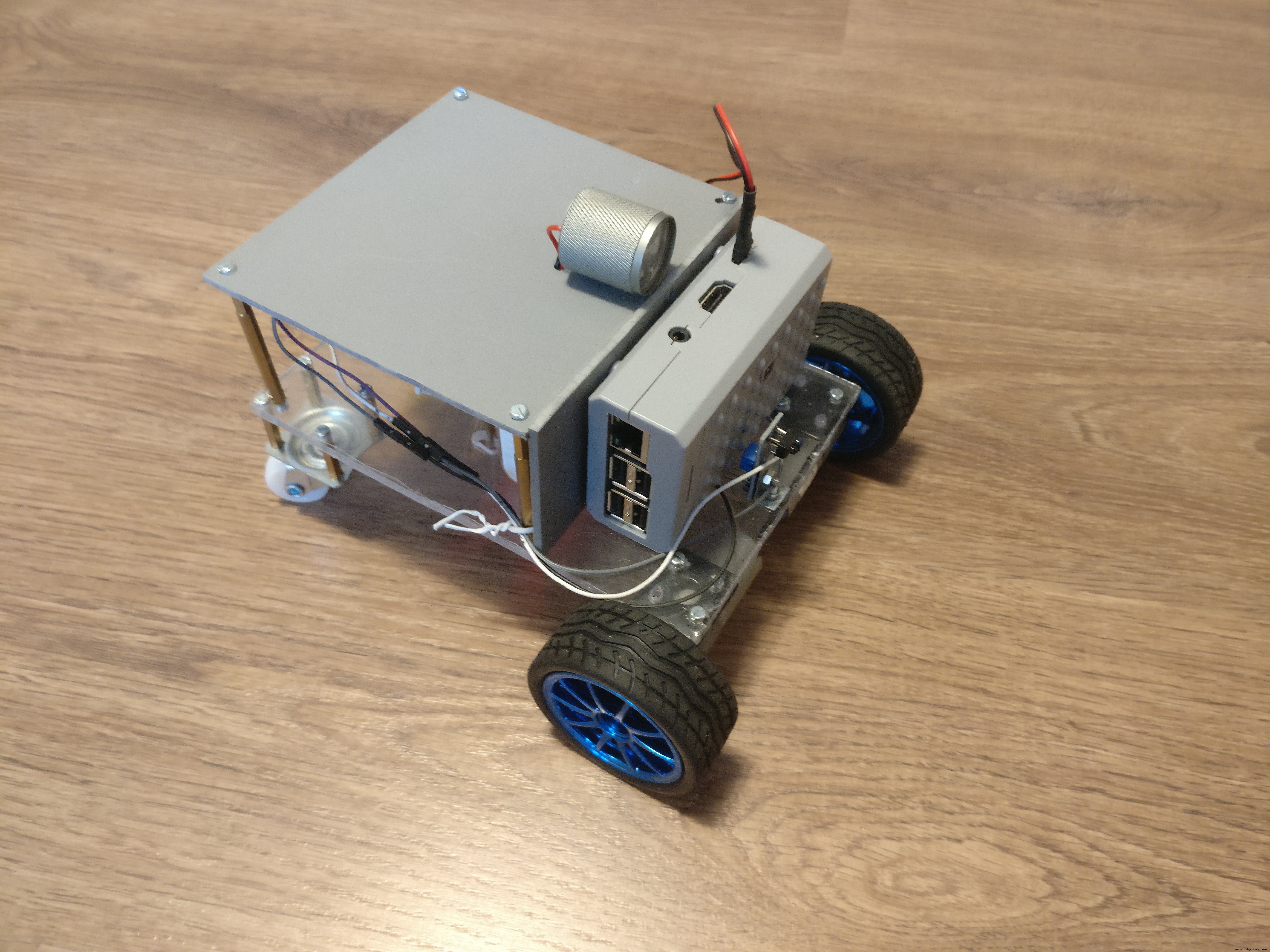
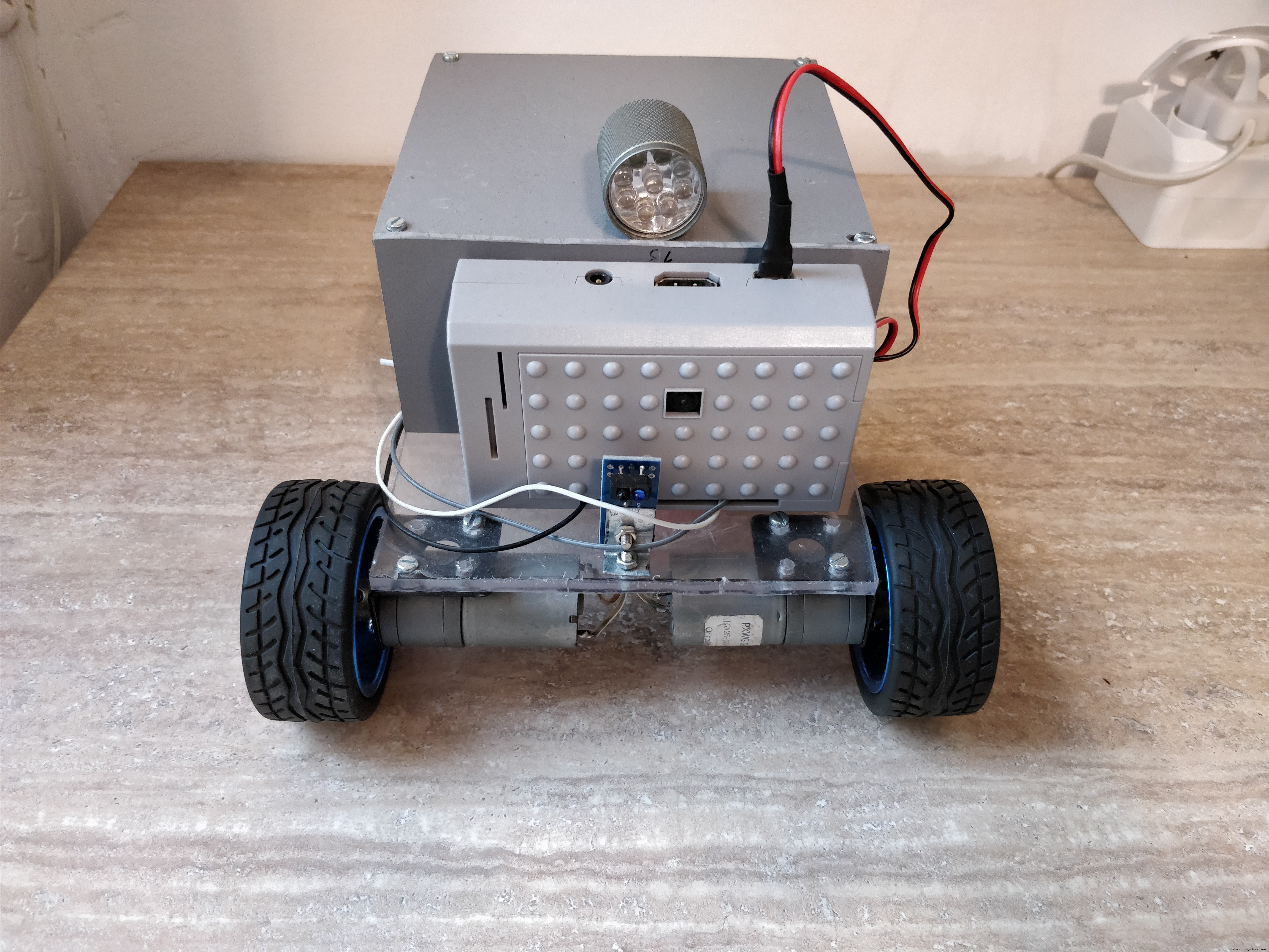
Bekijk de foto's voor bouwdetails!
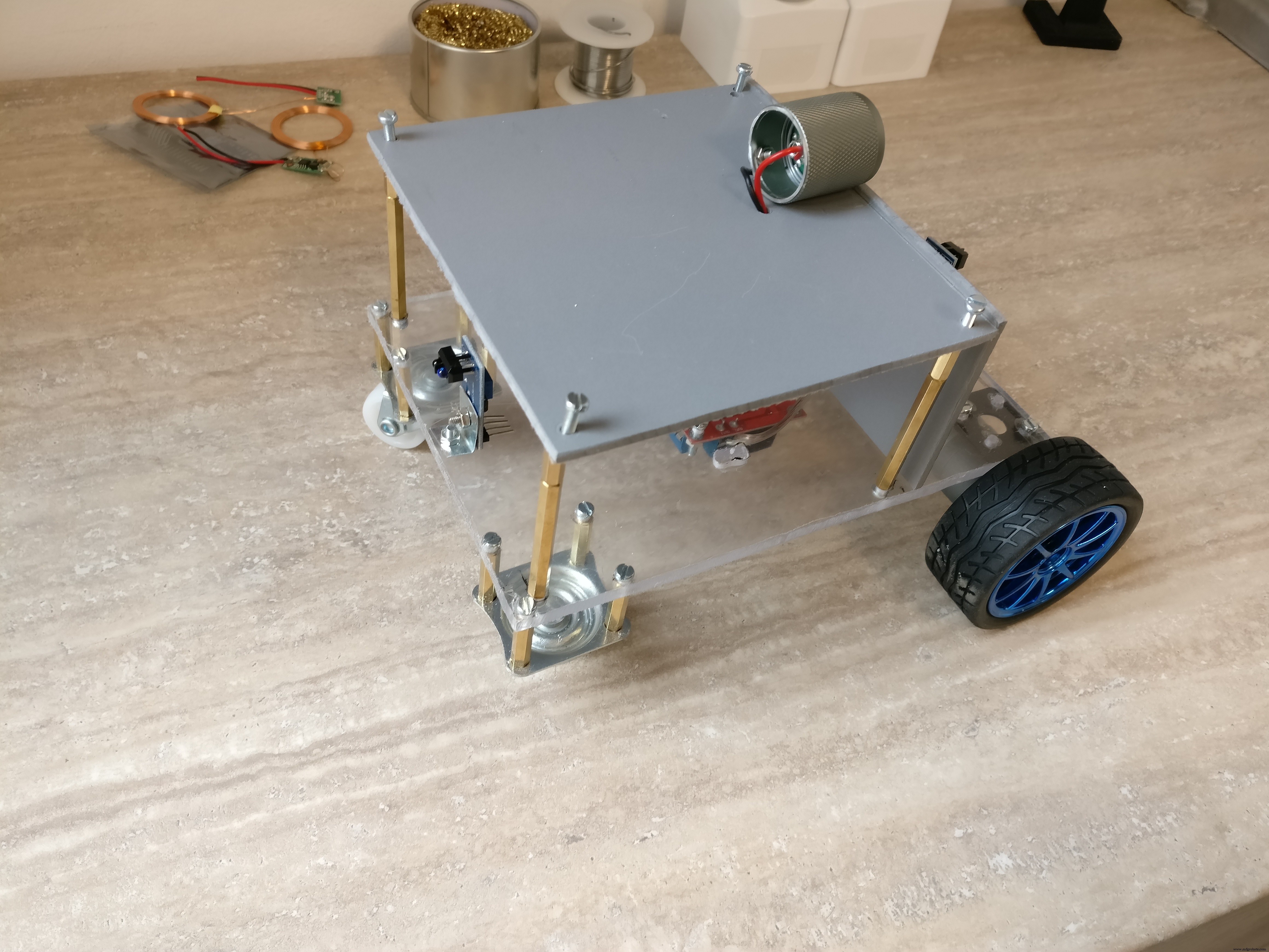
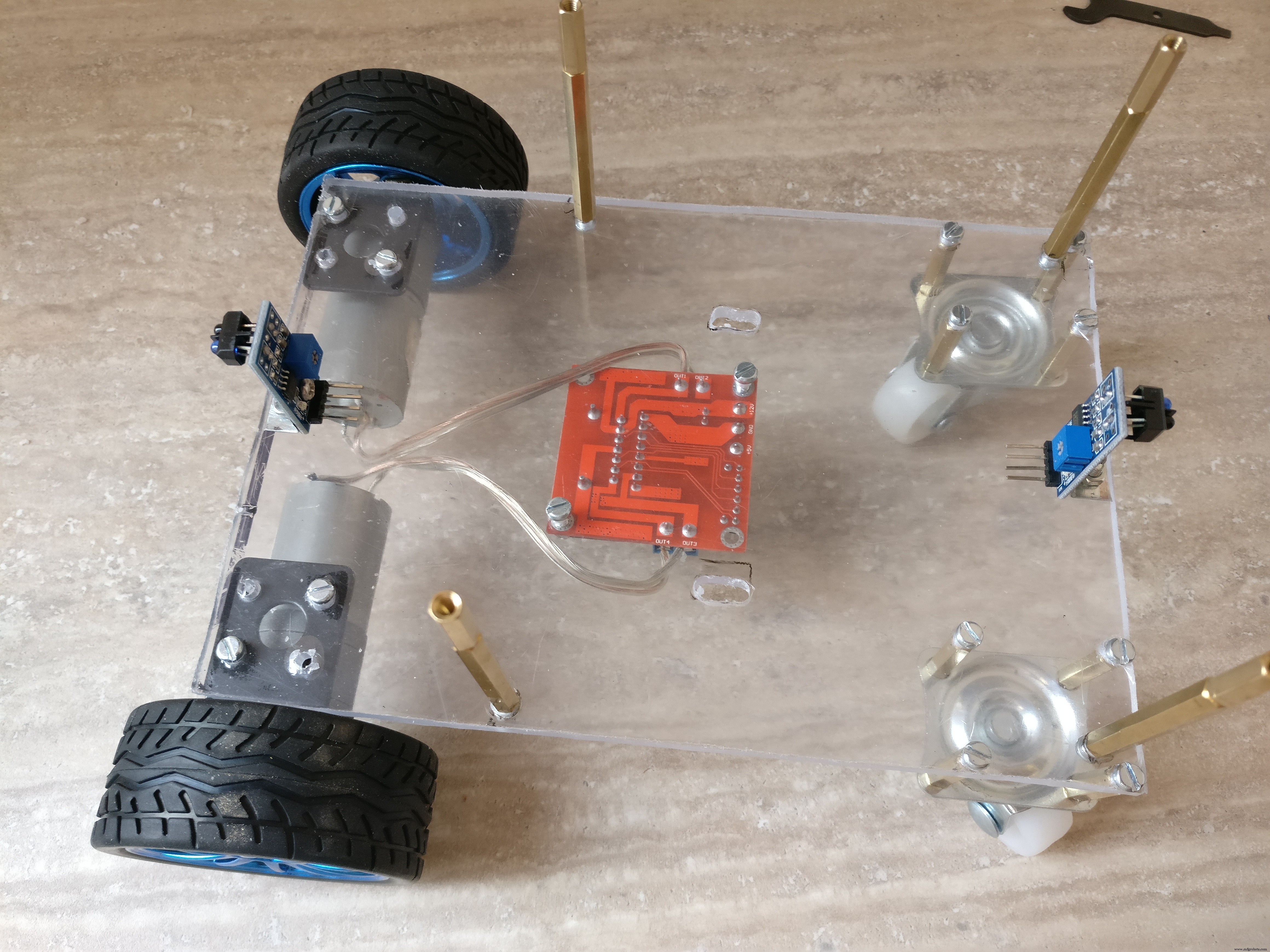
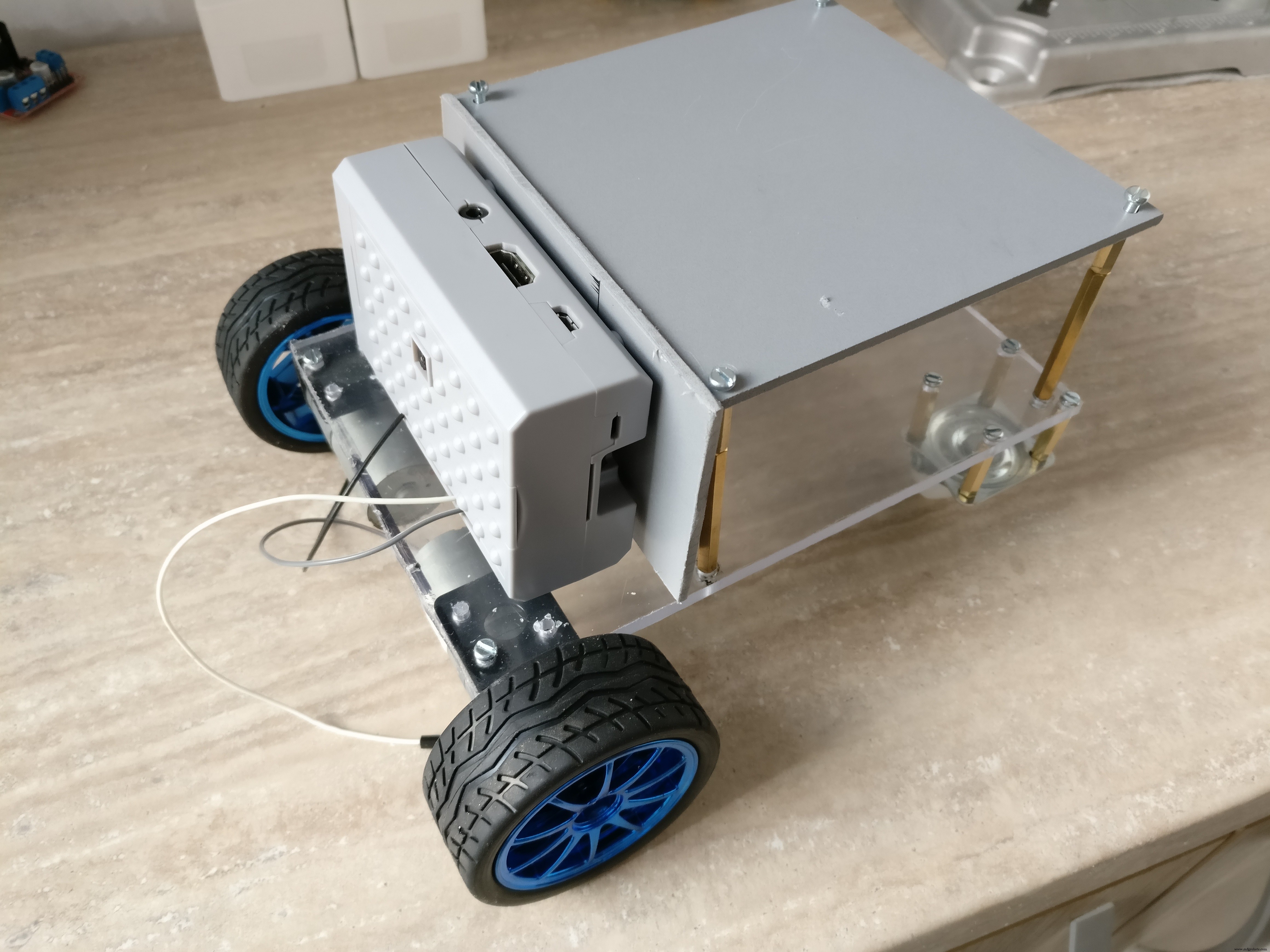
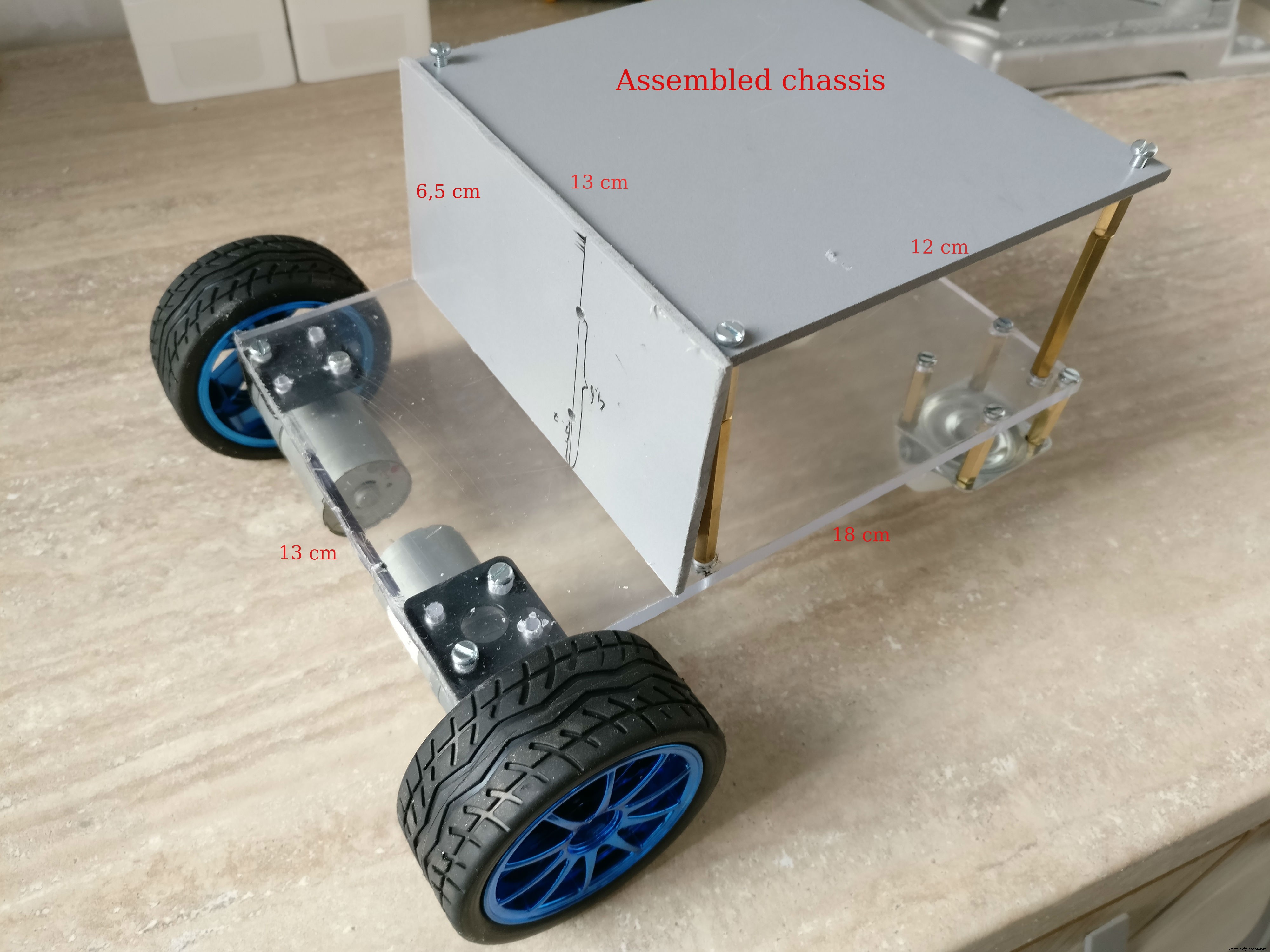
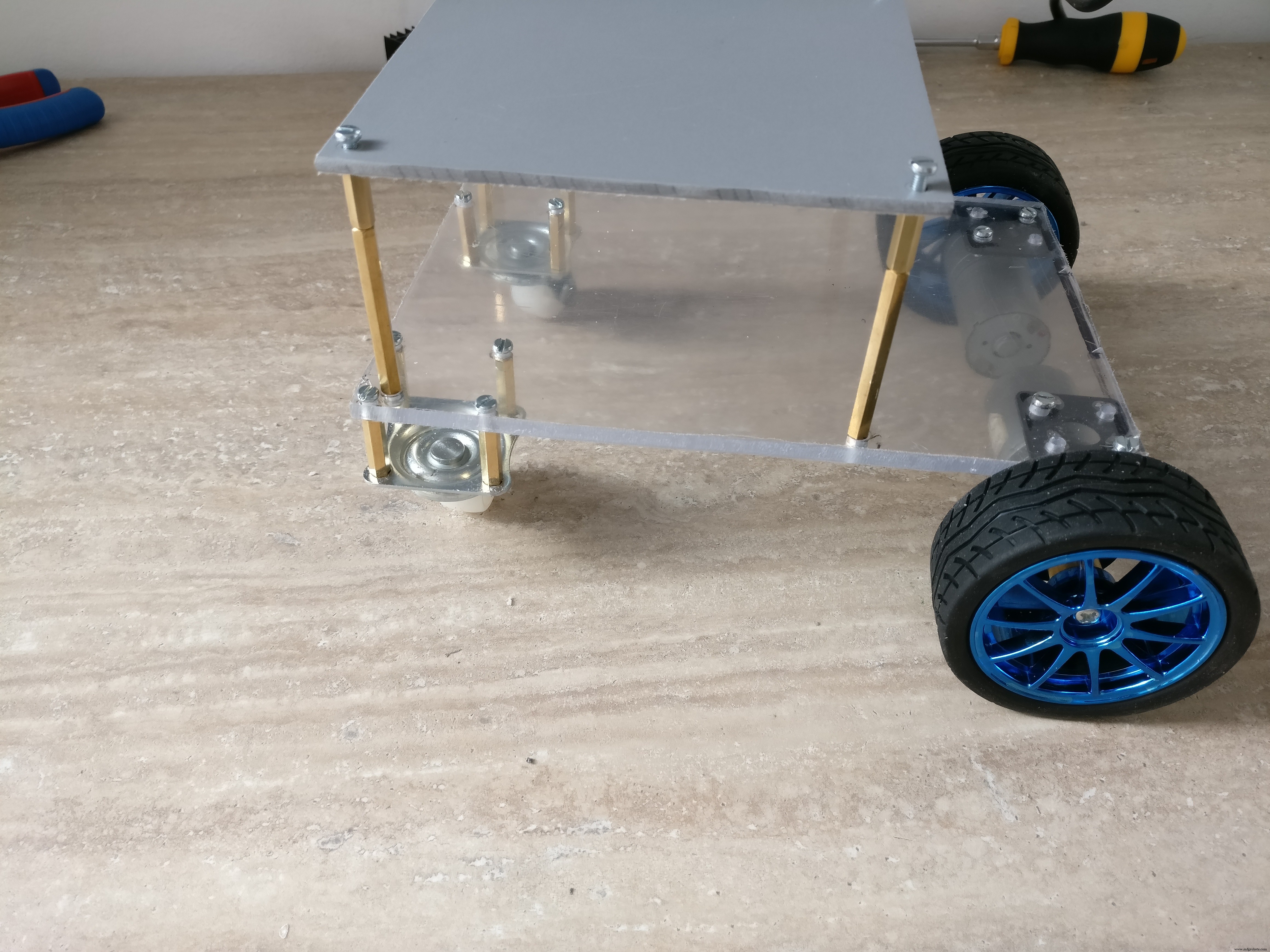
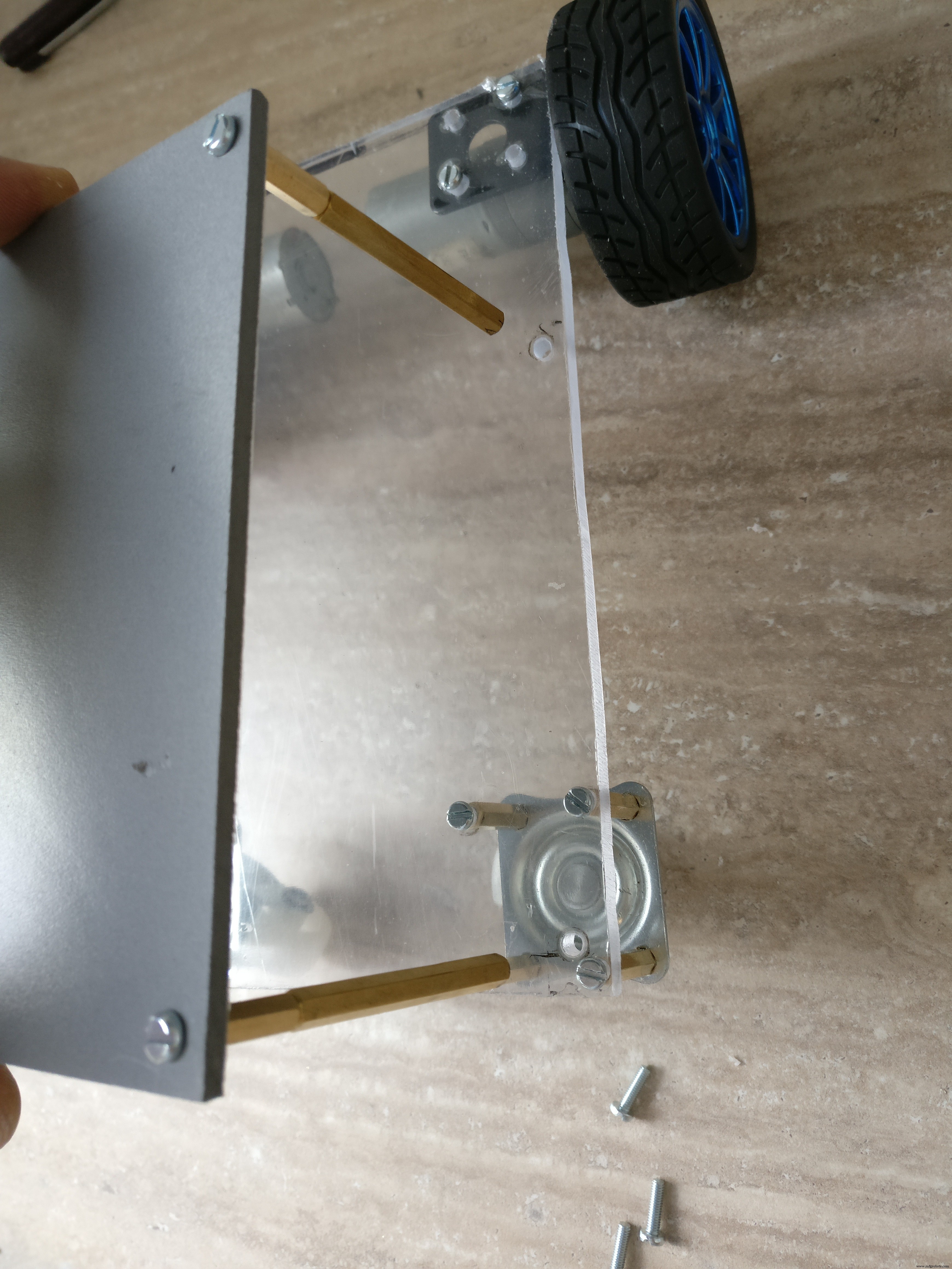
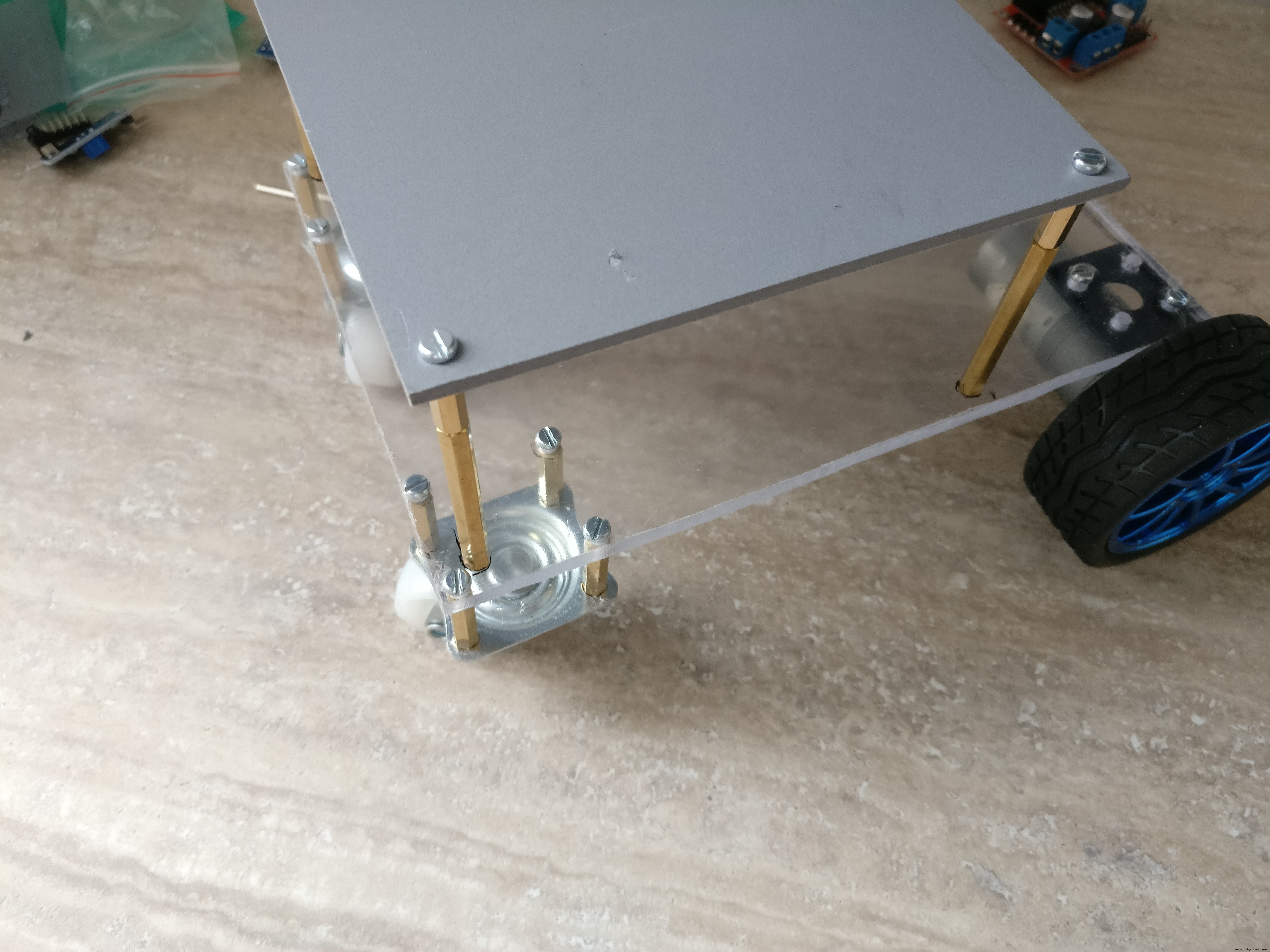
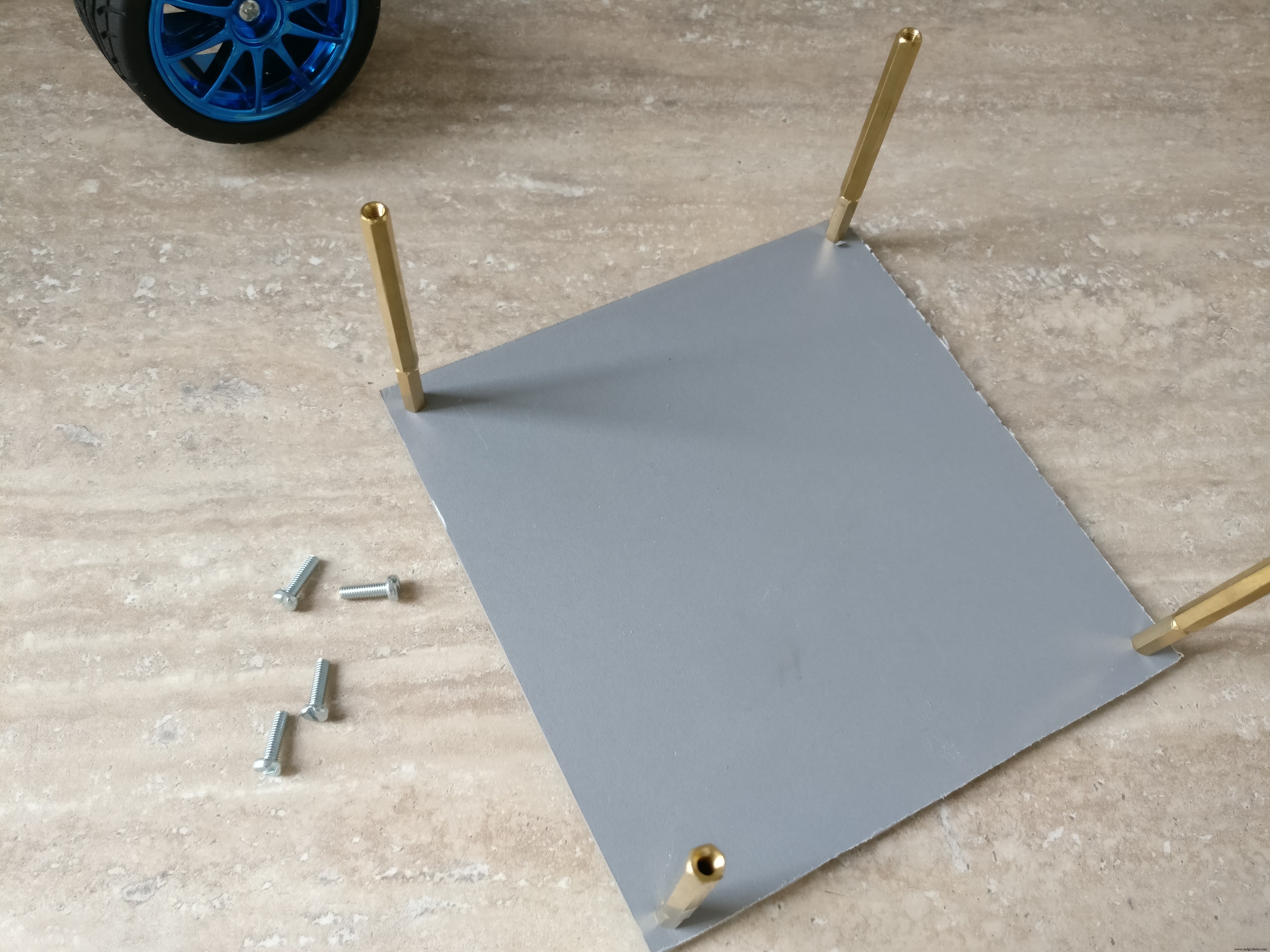
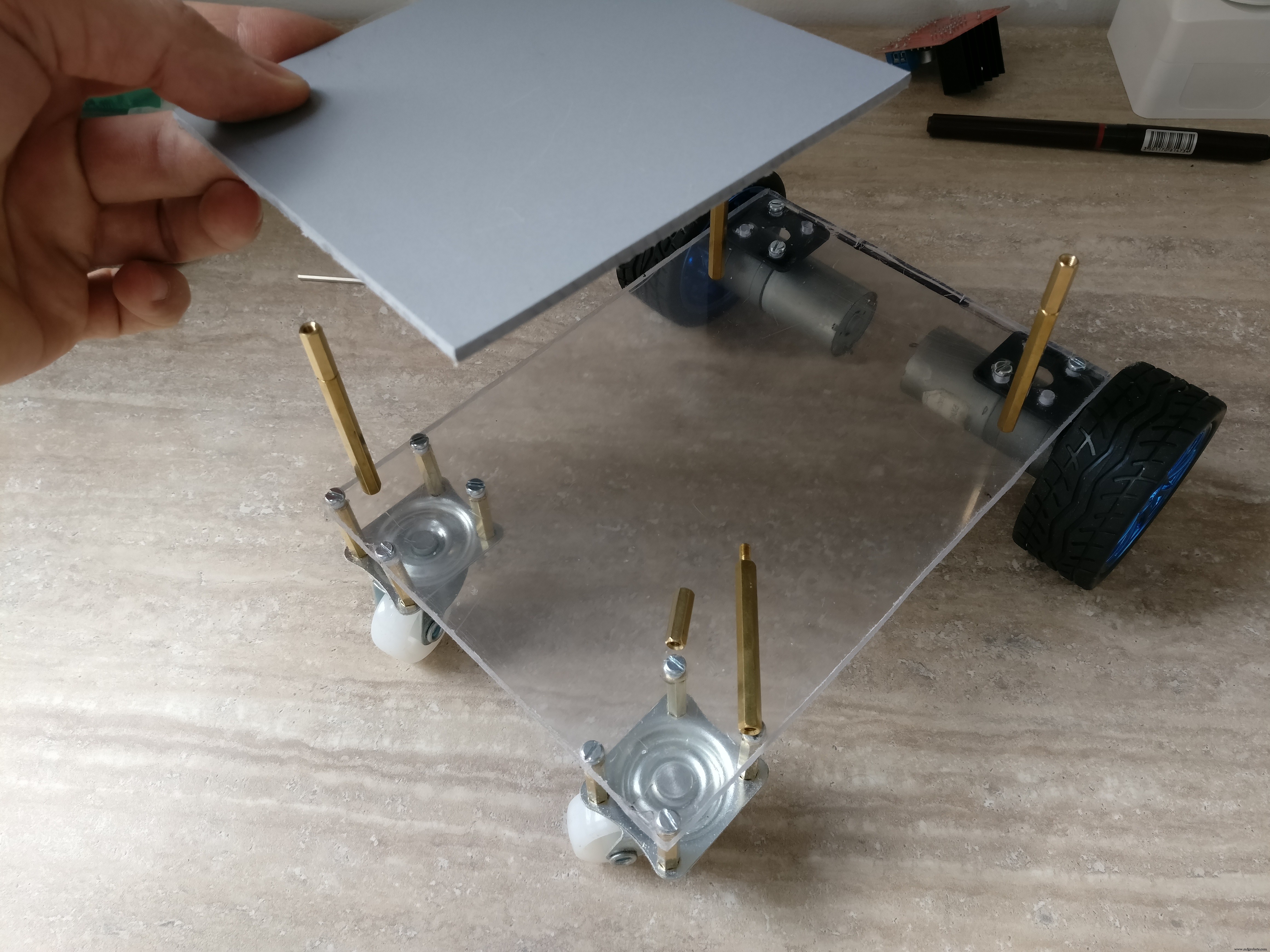
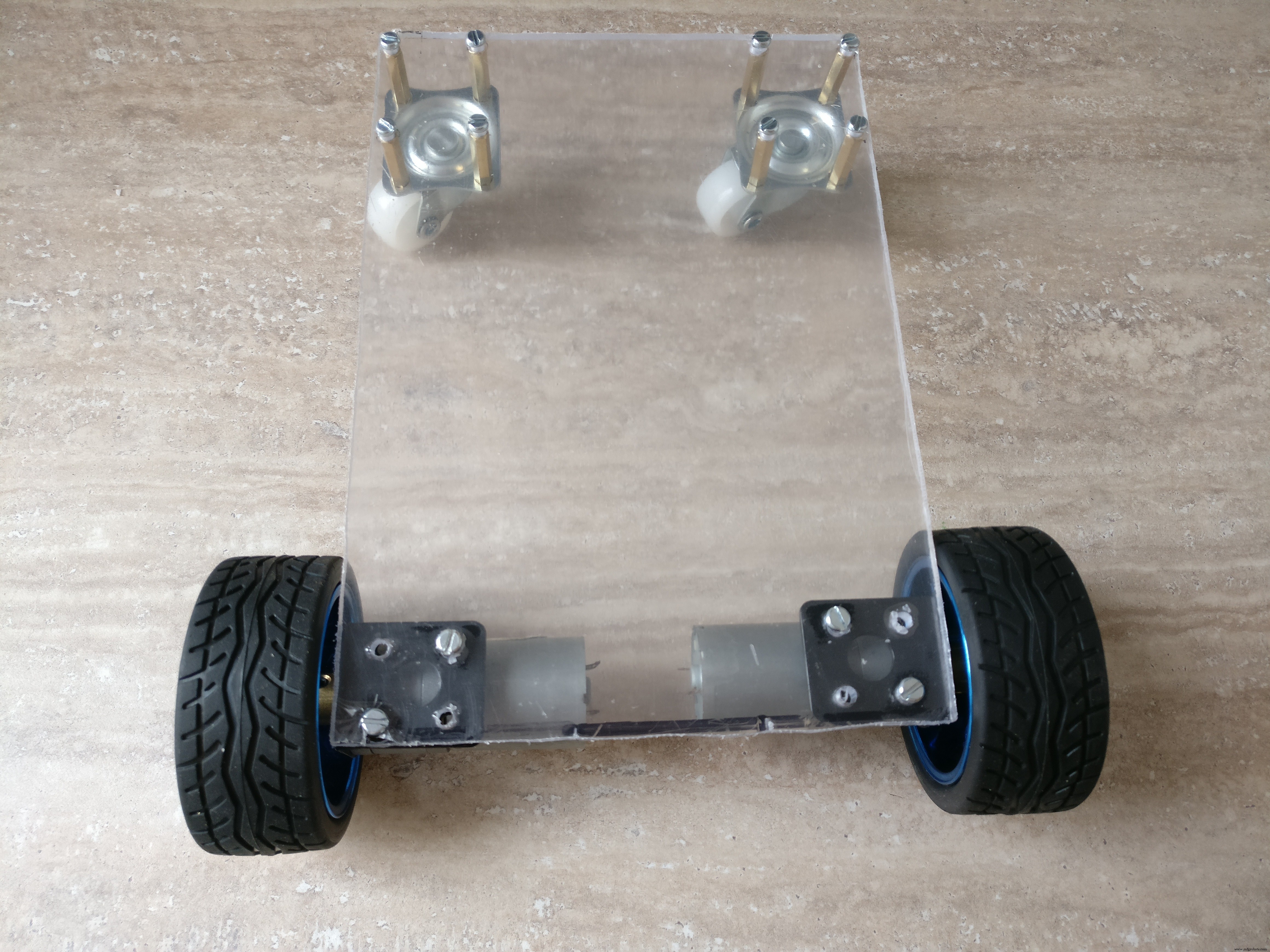
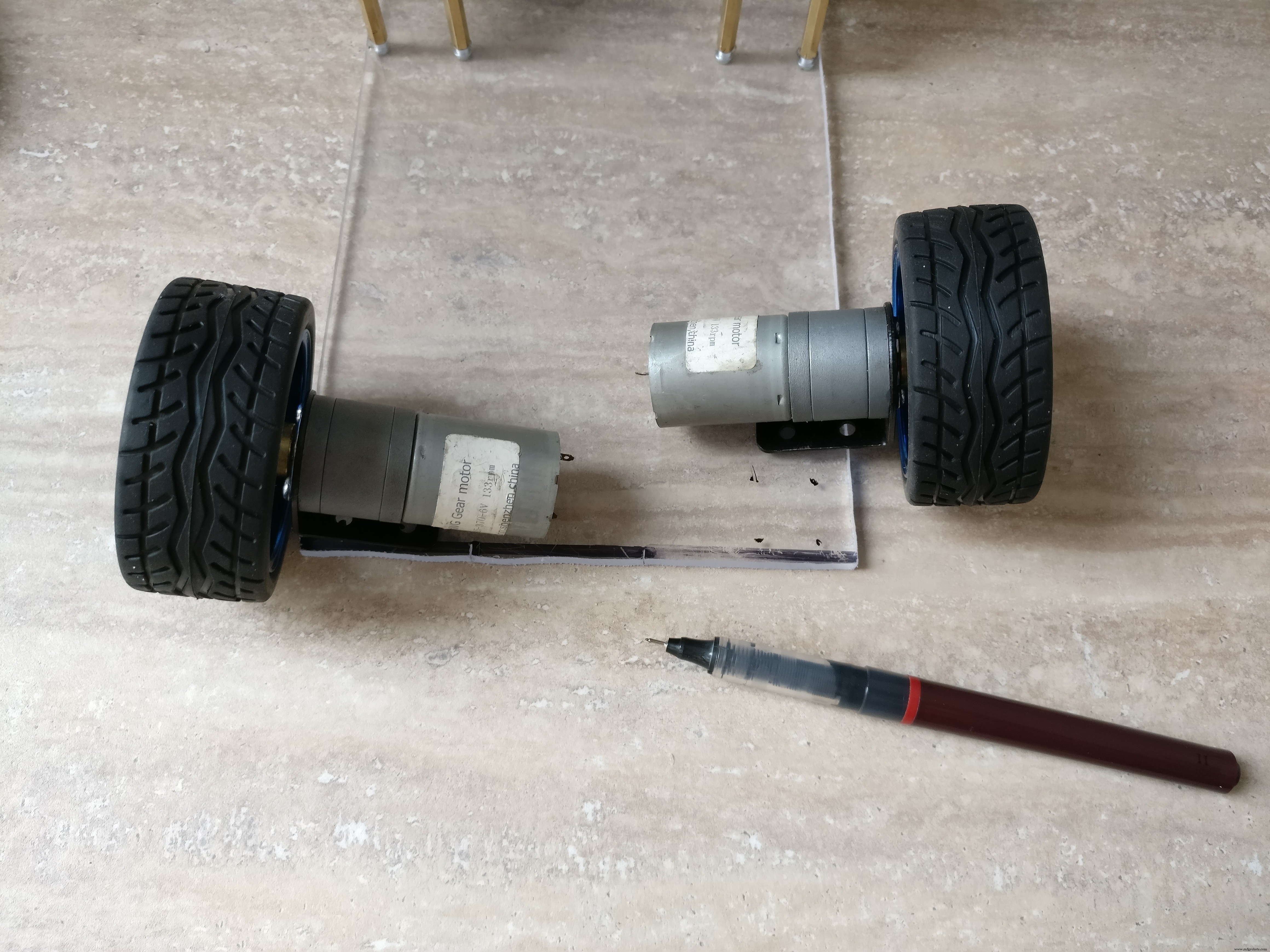
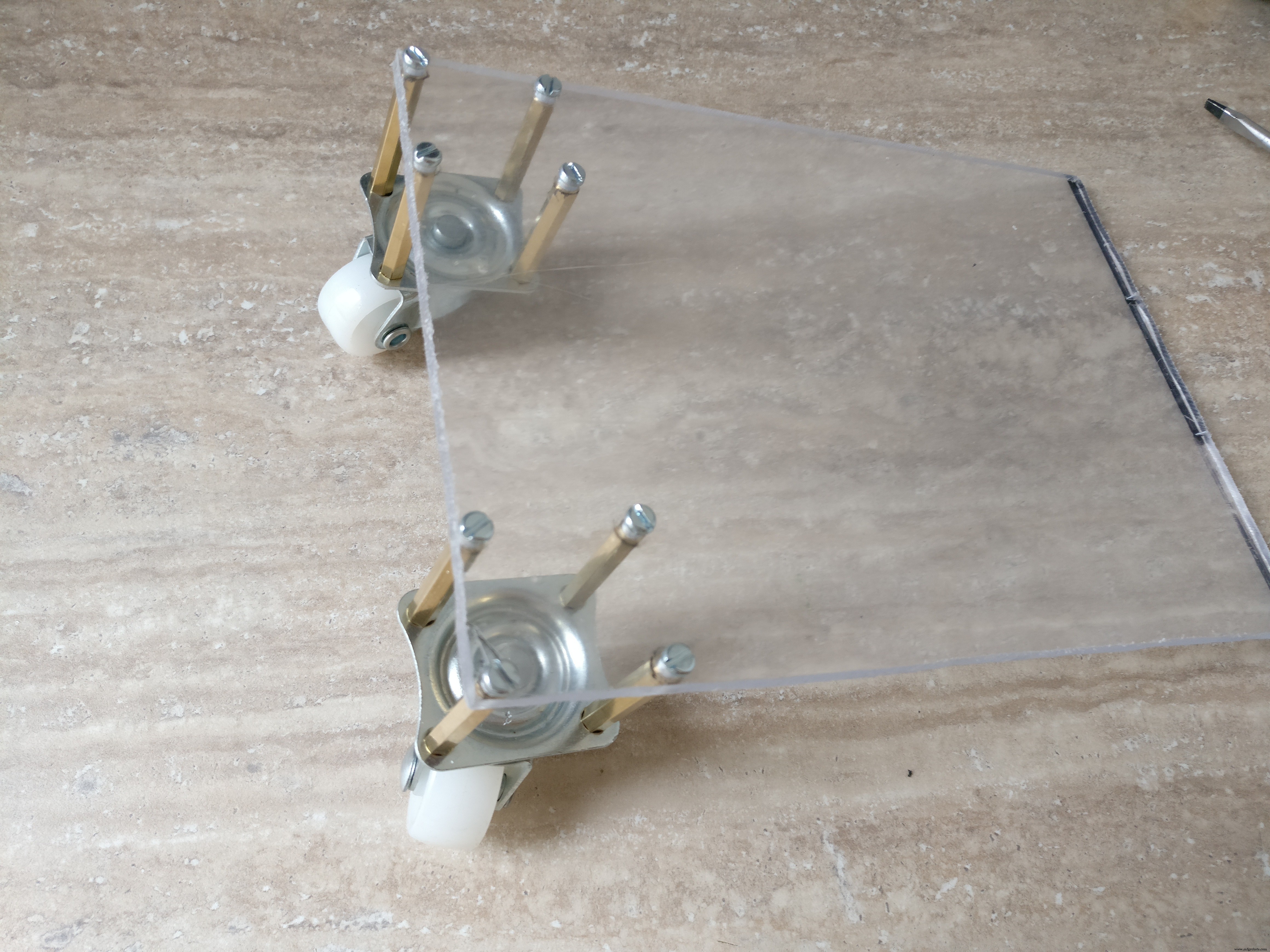
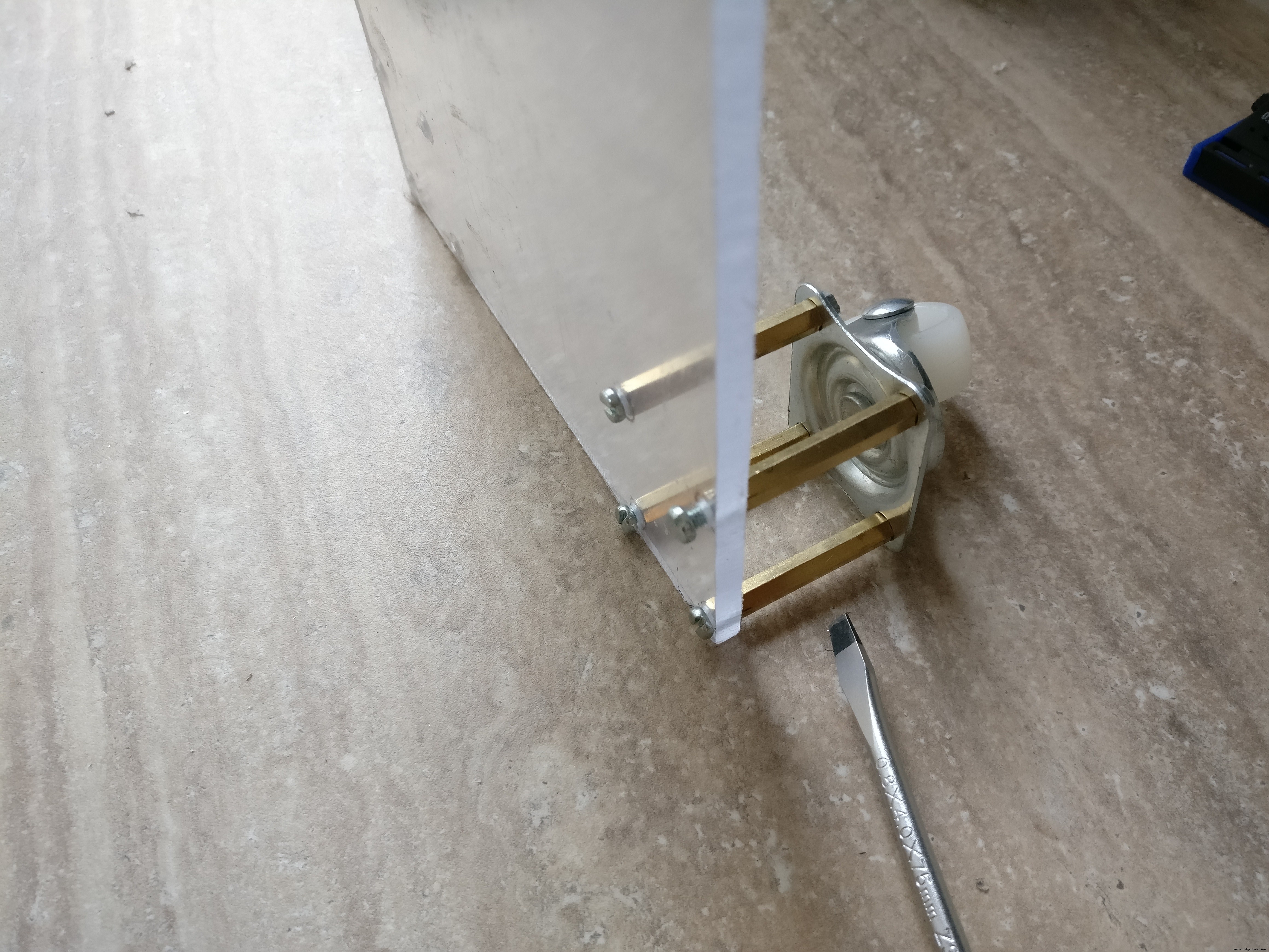
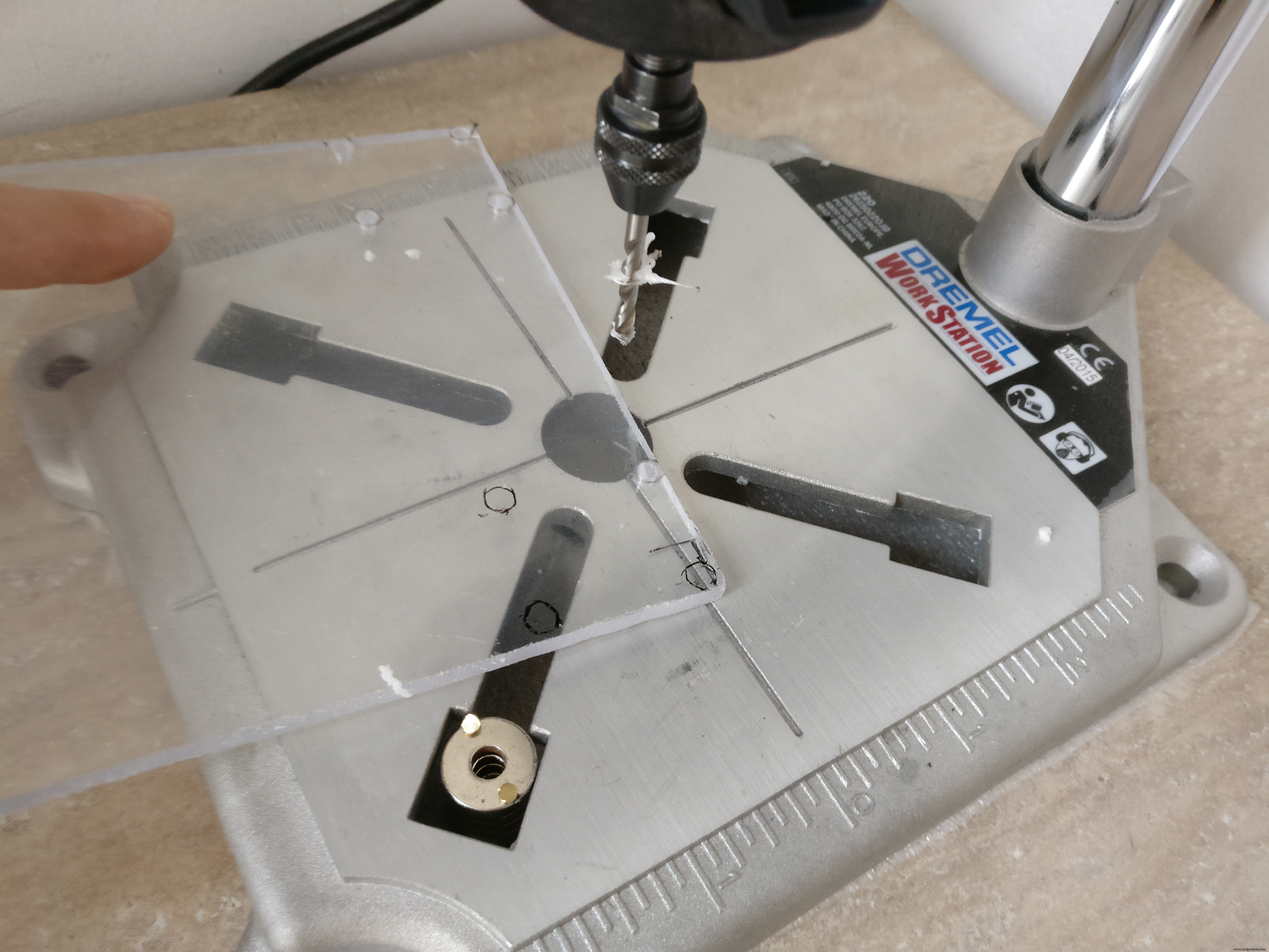
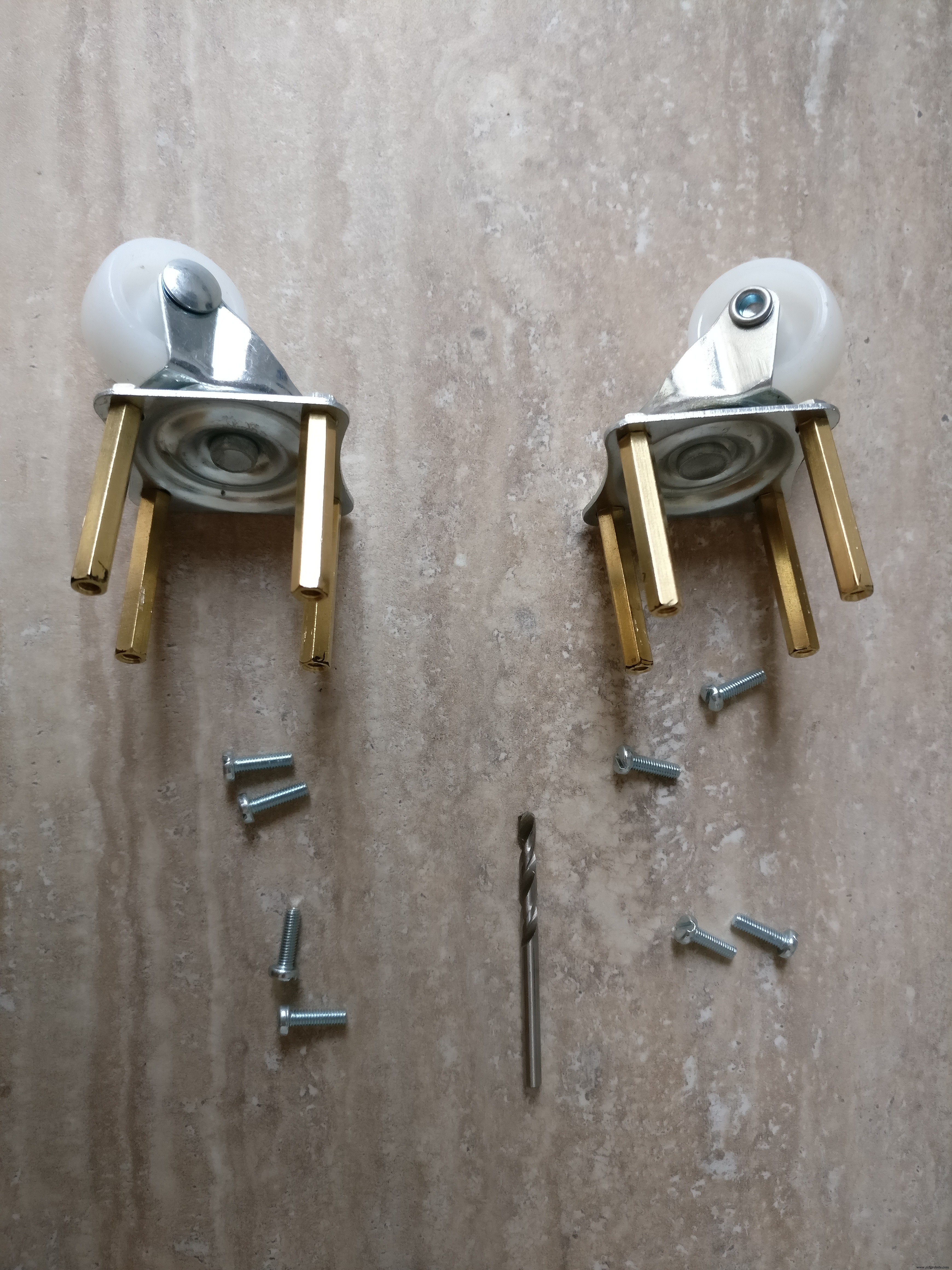
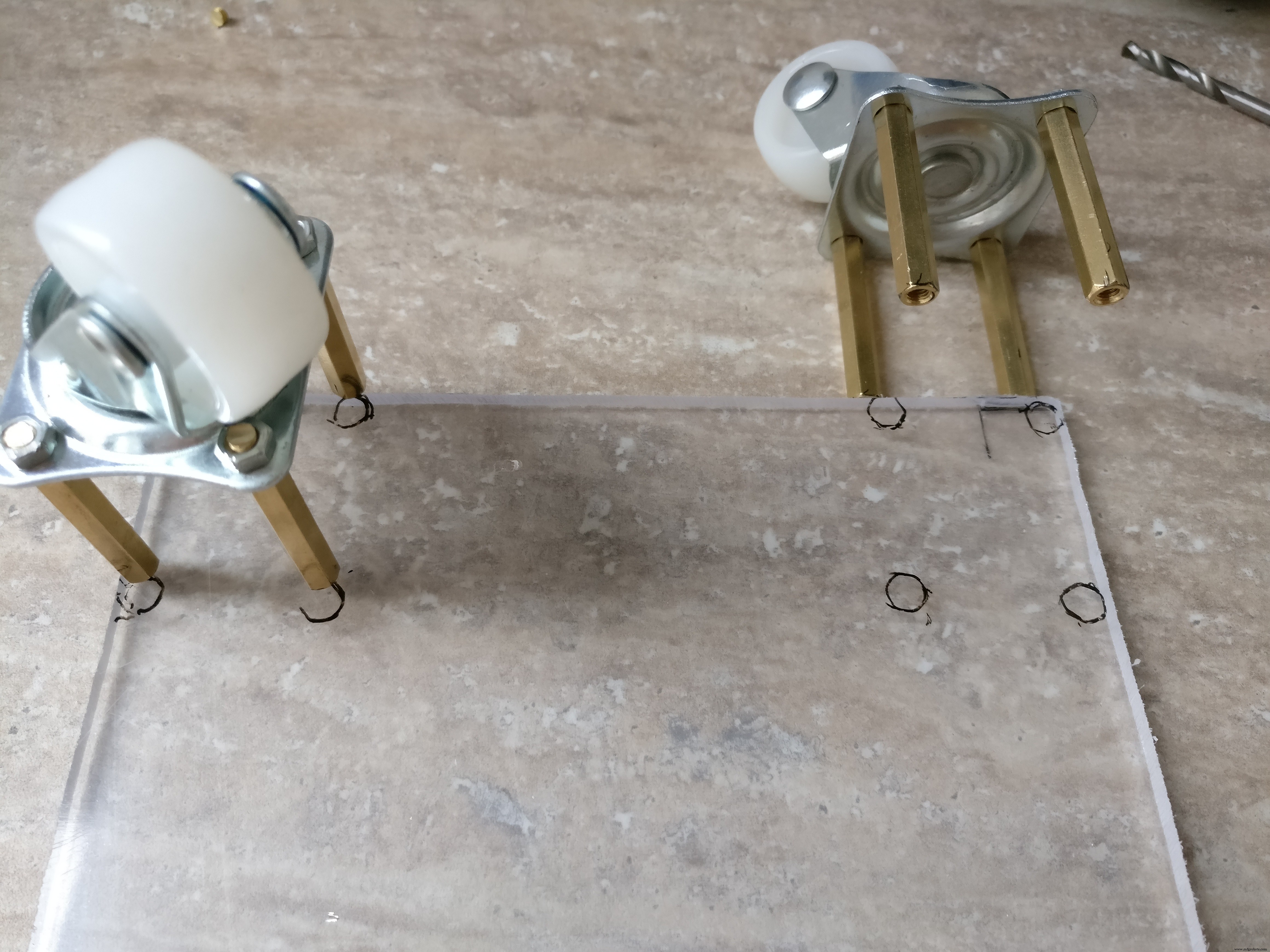
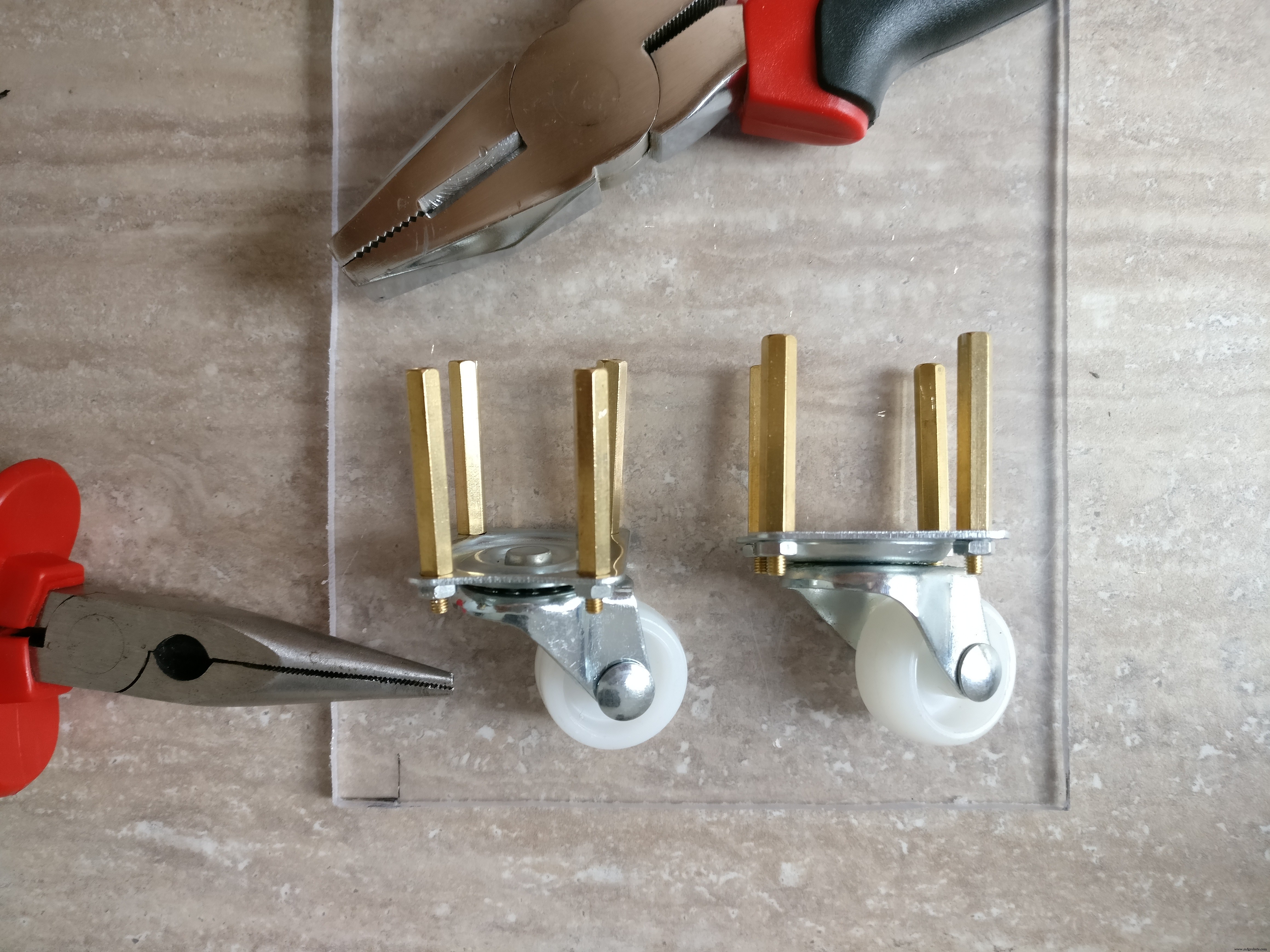
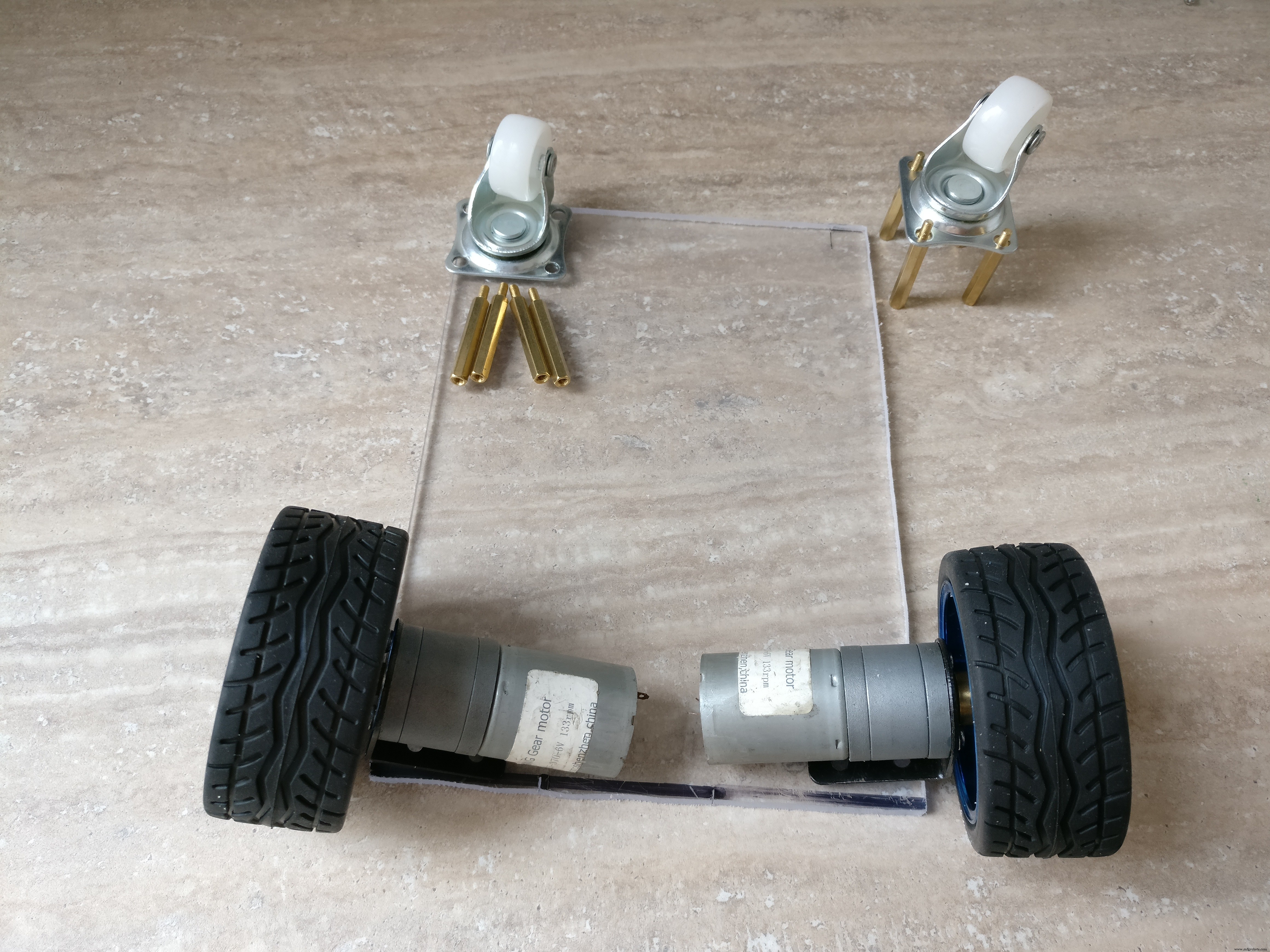

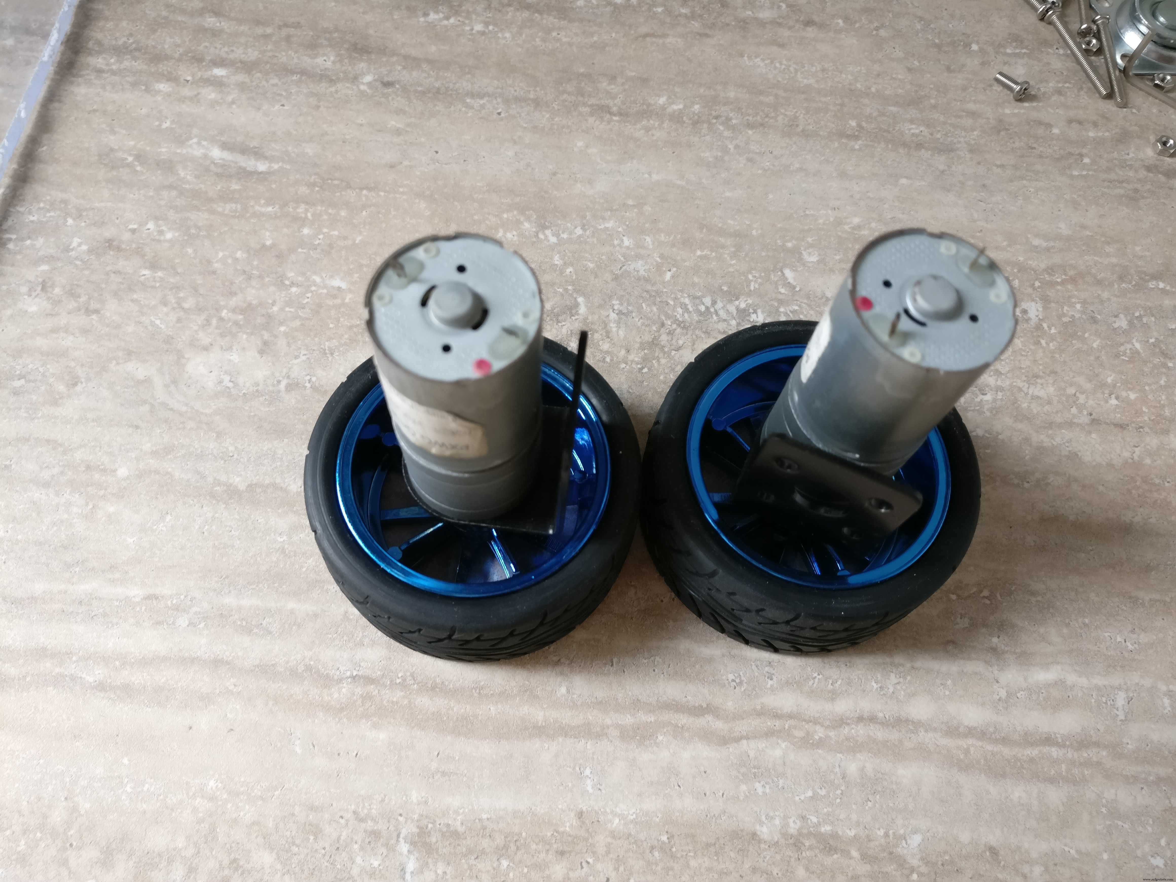
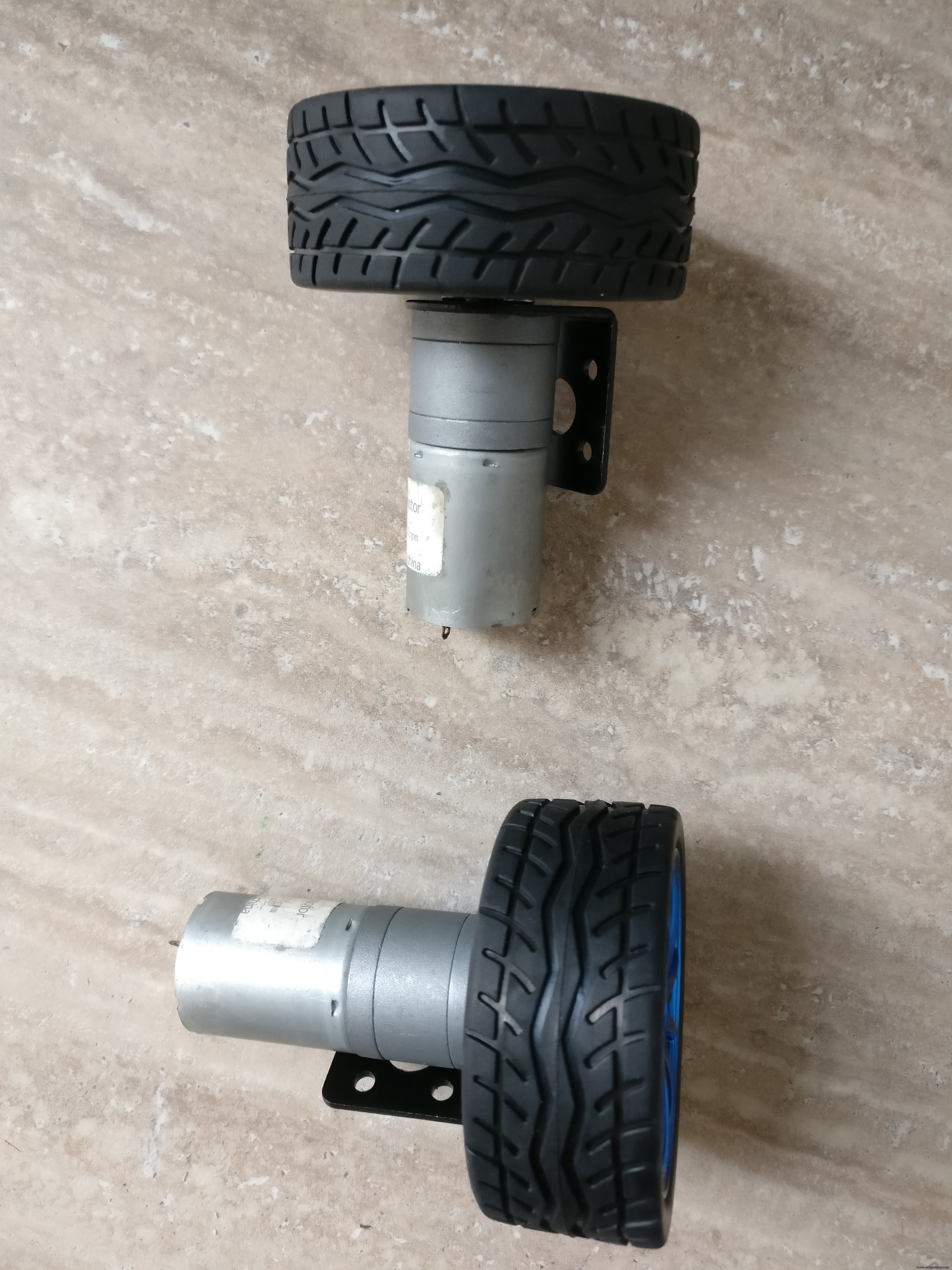
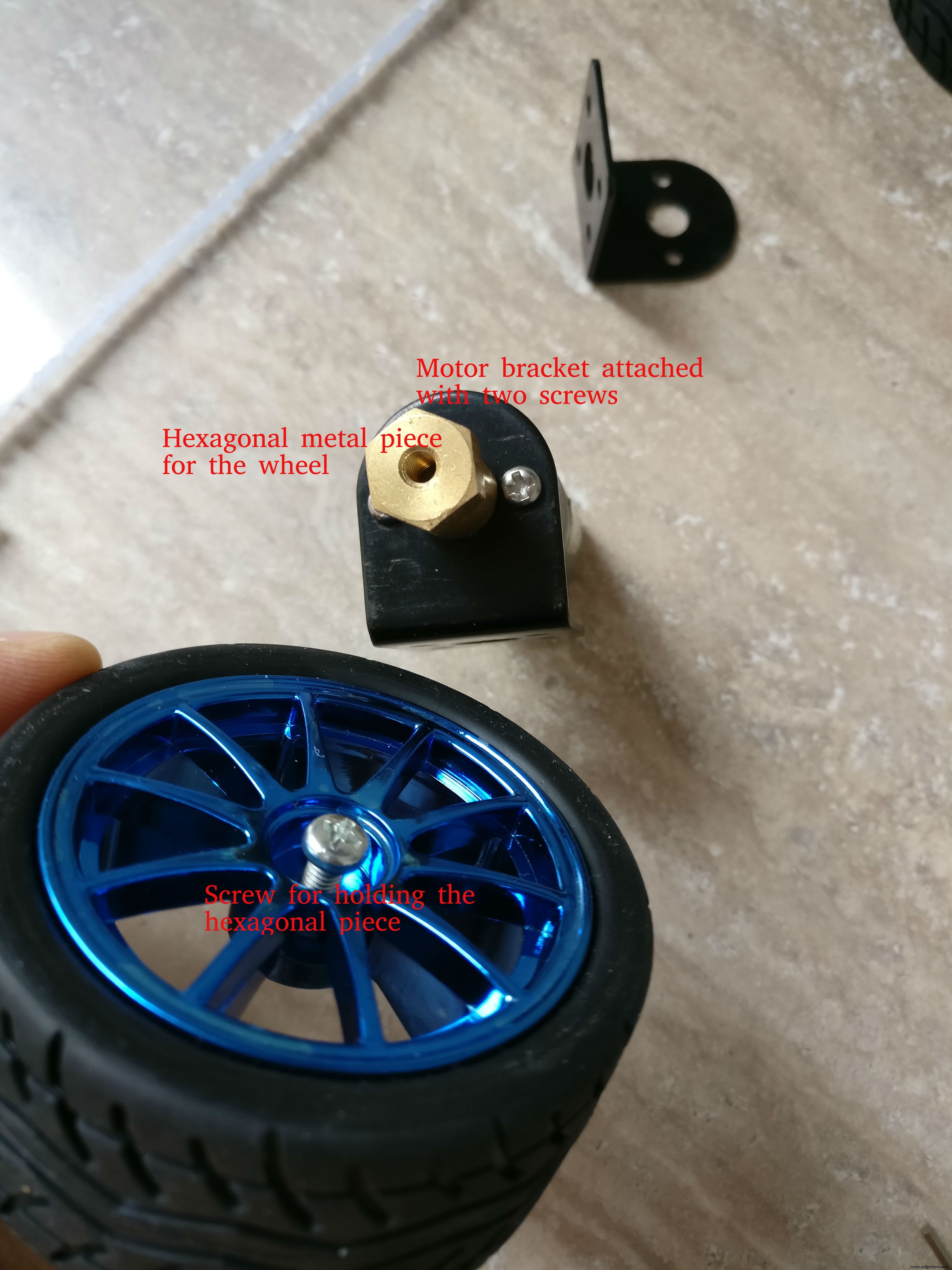
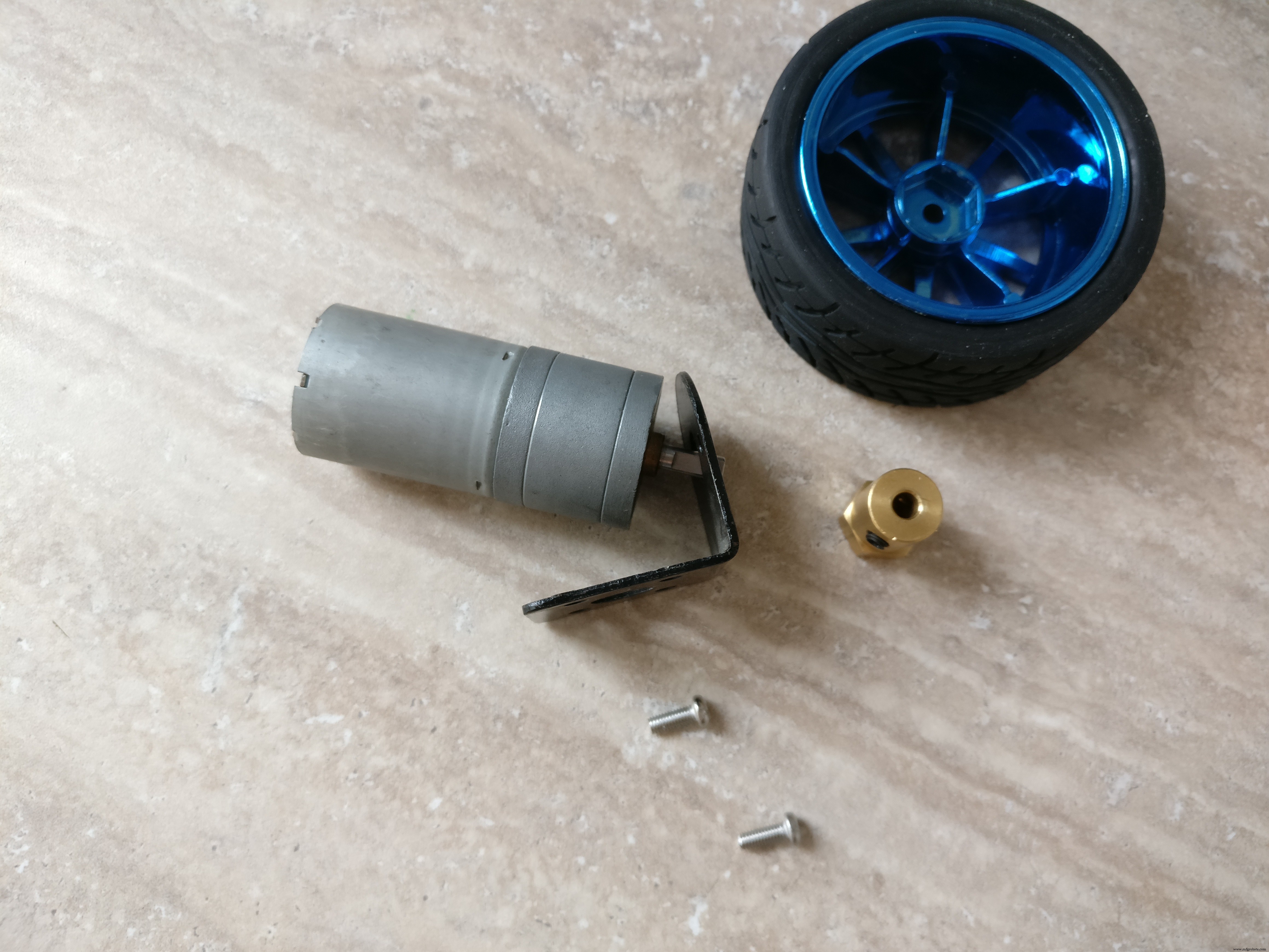
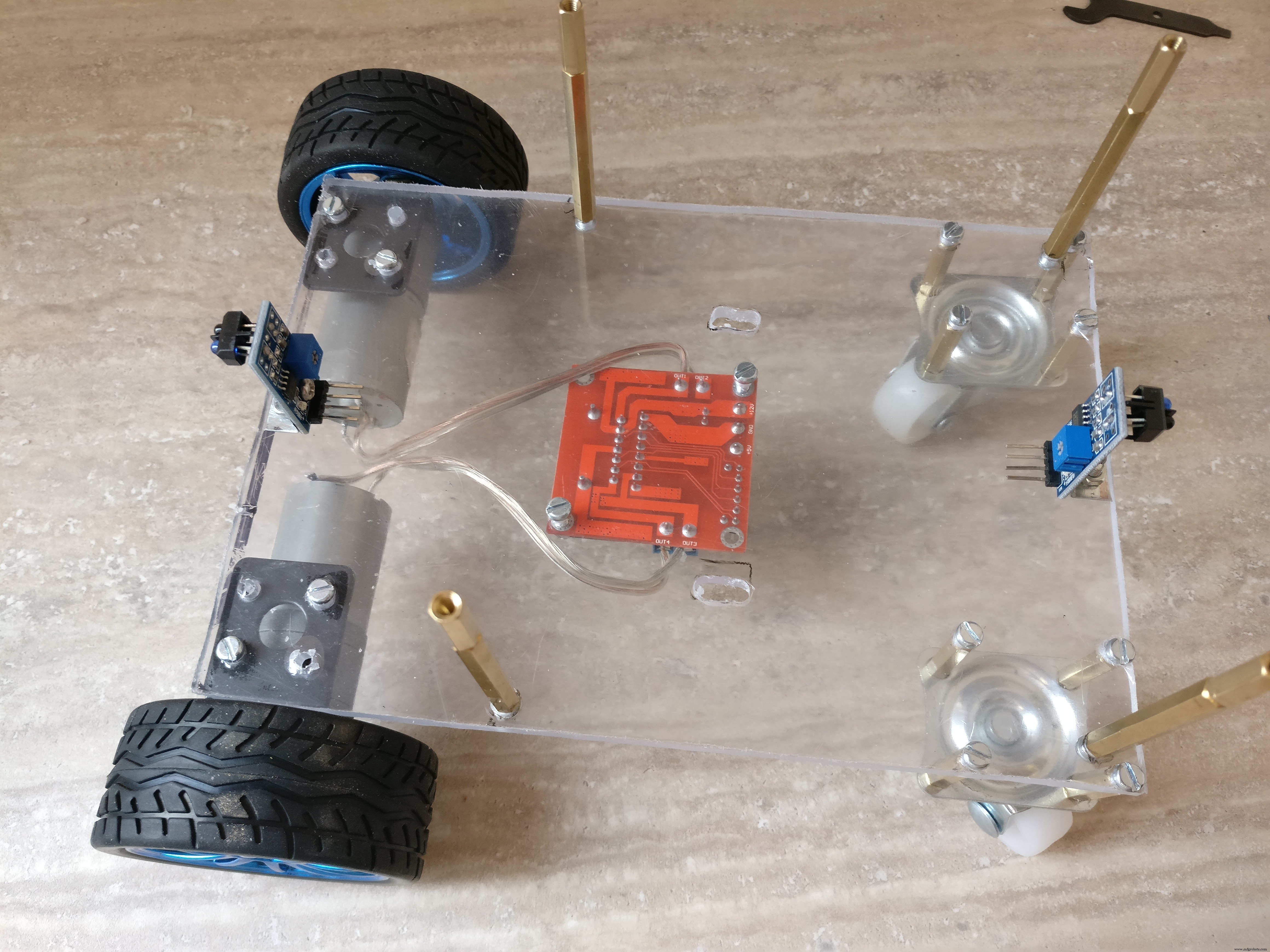
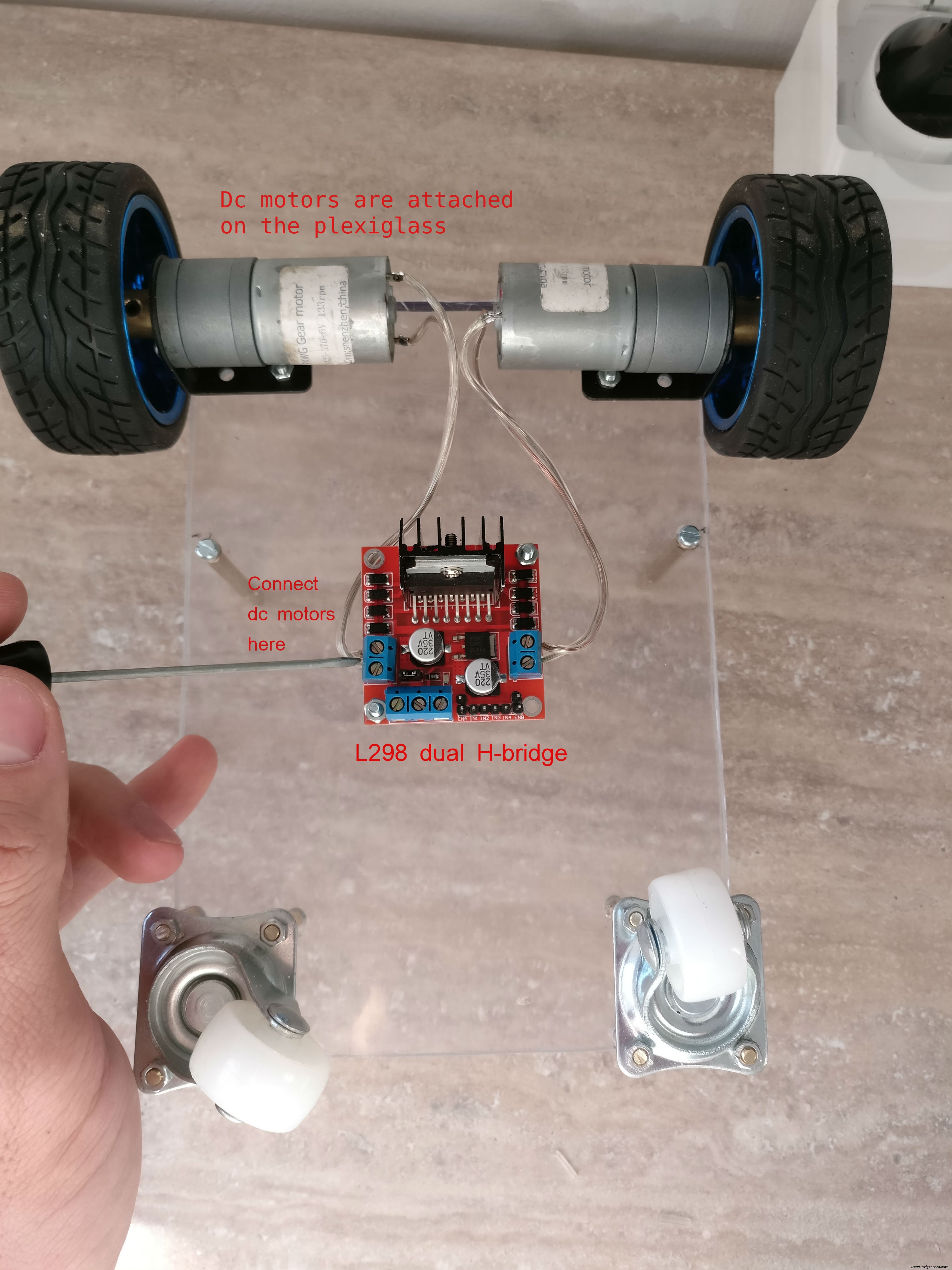
Basisplaat (18×13 cm): DC-motoren met metalen beugels. H-brug onderin midden. Achterwielen op 2 cm zeshoekse afstandsbusjes. Groot gat bij H-brug voor doorvoering kabels naar boven.
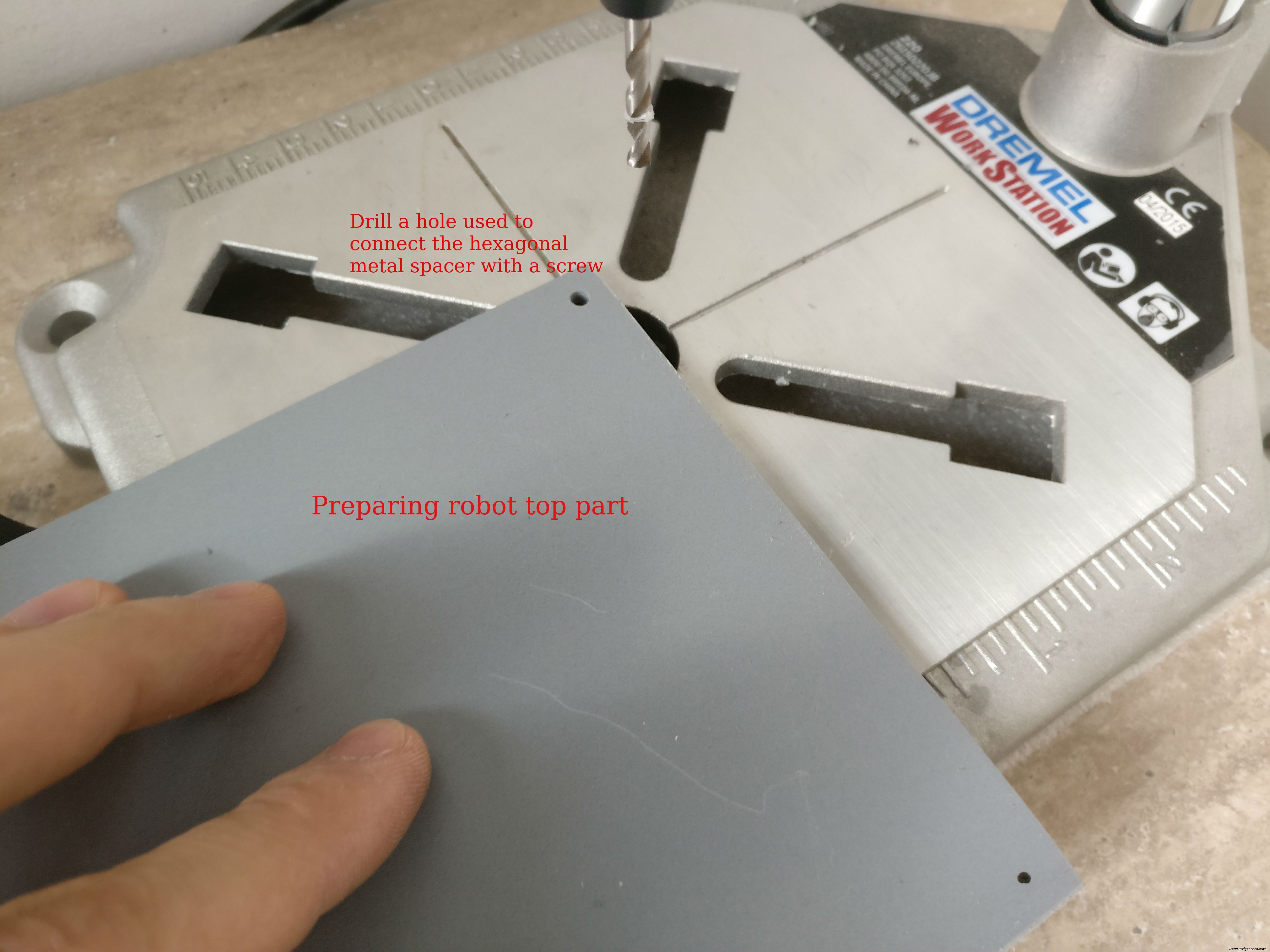
Bovenplaat (L-vormig): 12×13 cm + 6,5×13 cm, samen gelijmd. Beschermt elektronica, draagt hoofdlicht en Pi-behuizing. Bevestigd met 6 cm afstandsbusjes op basisplaat.
Stap 3: Elektronica bouwen
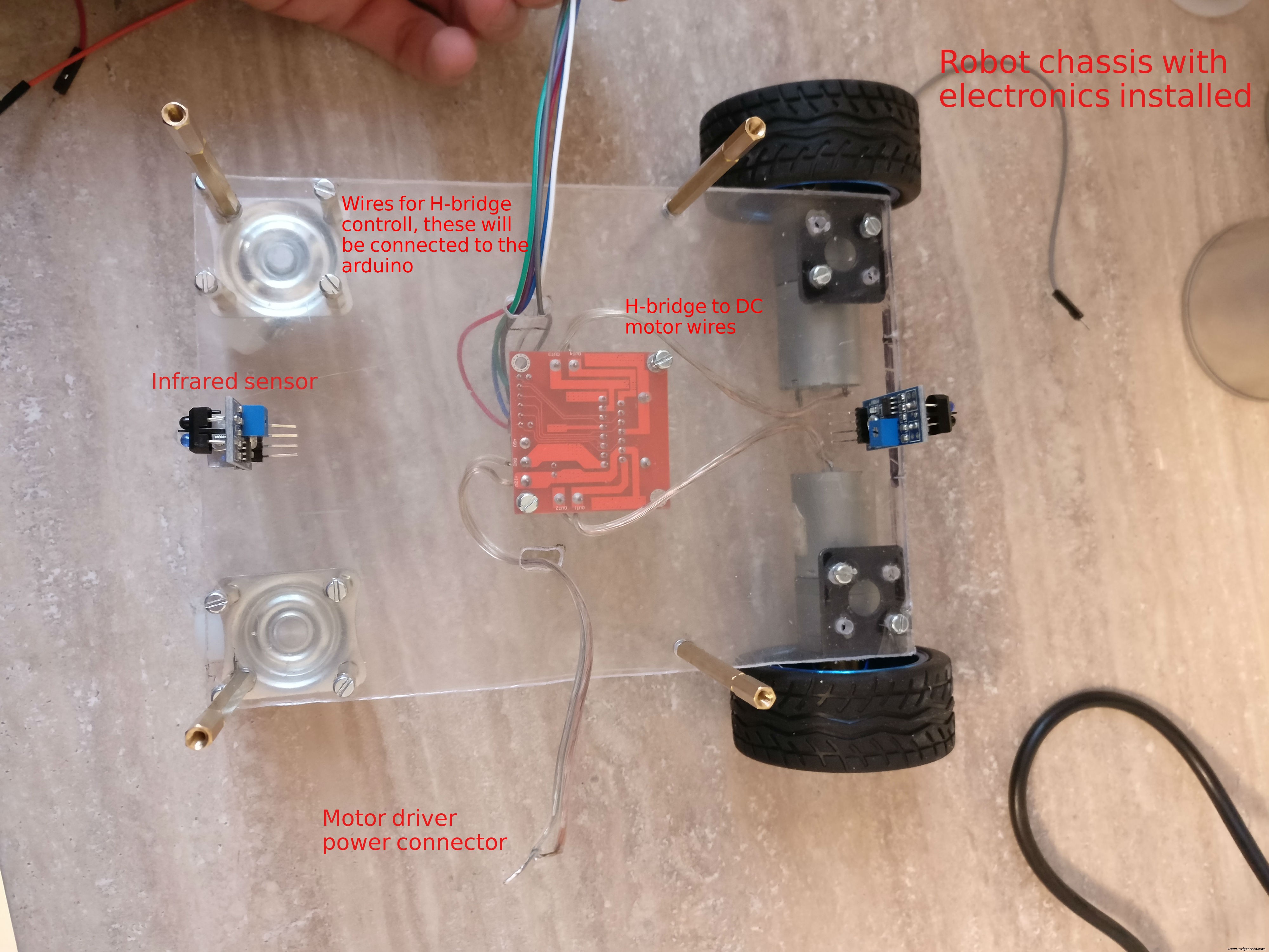
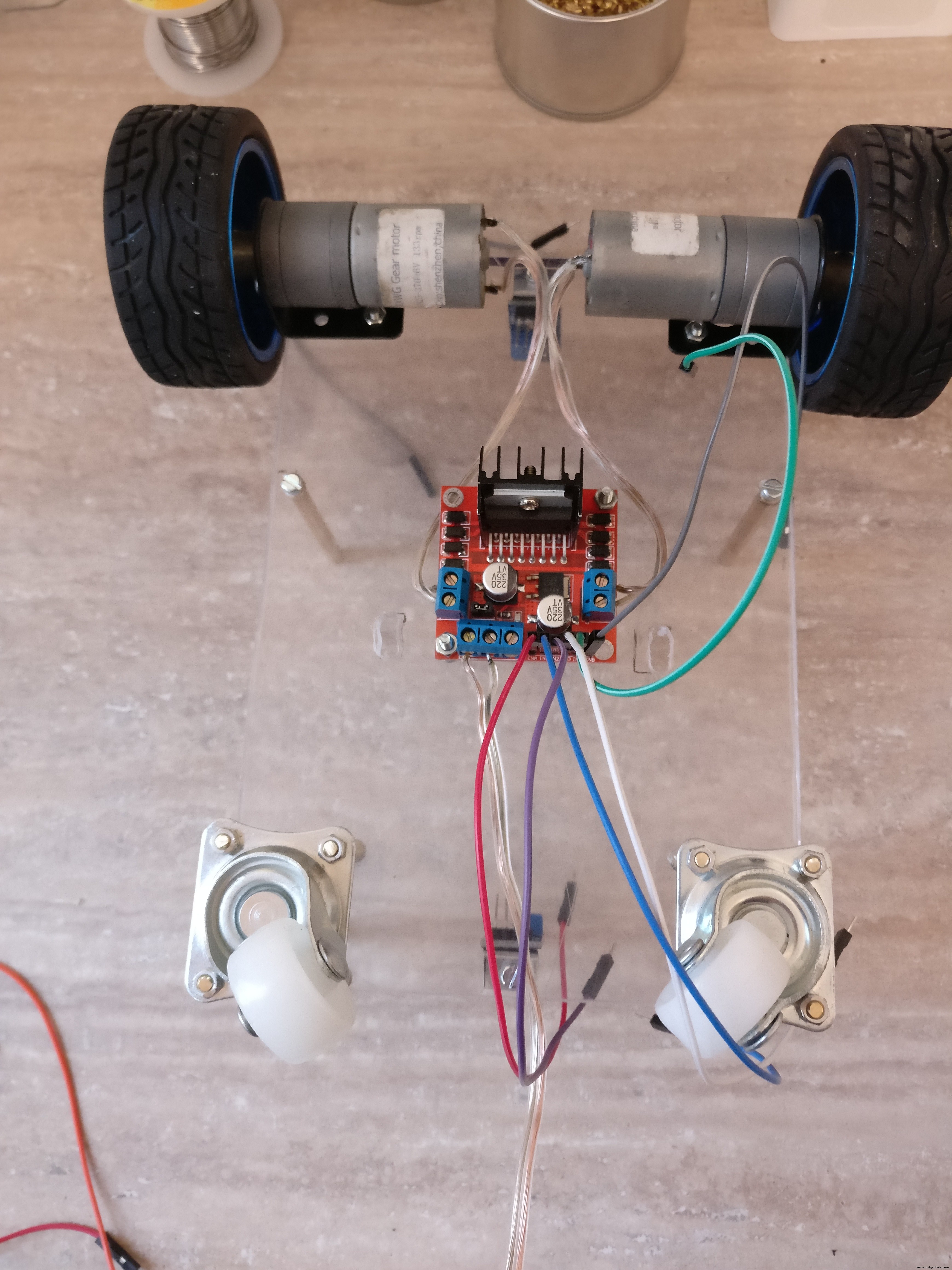
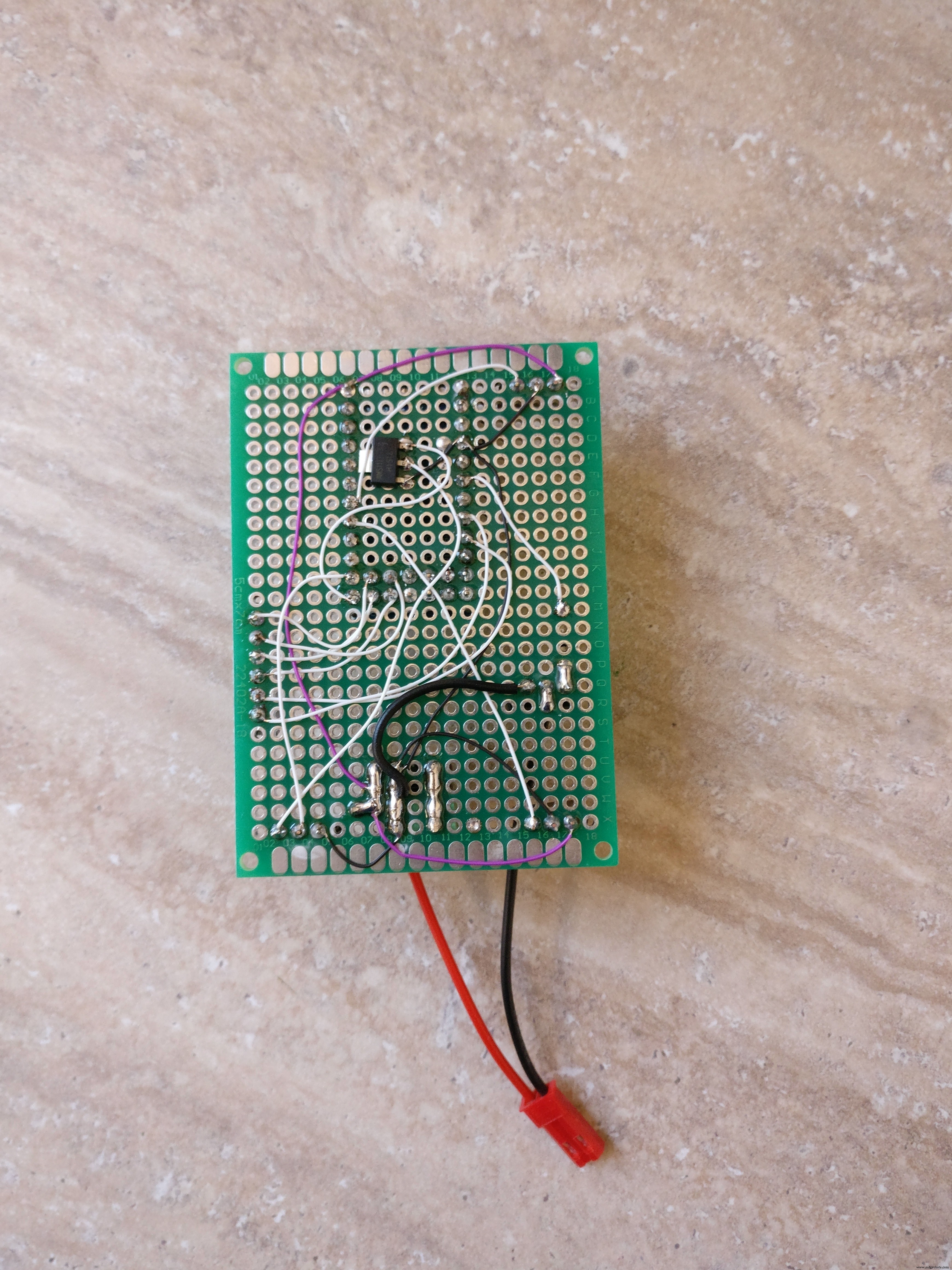
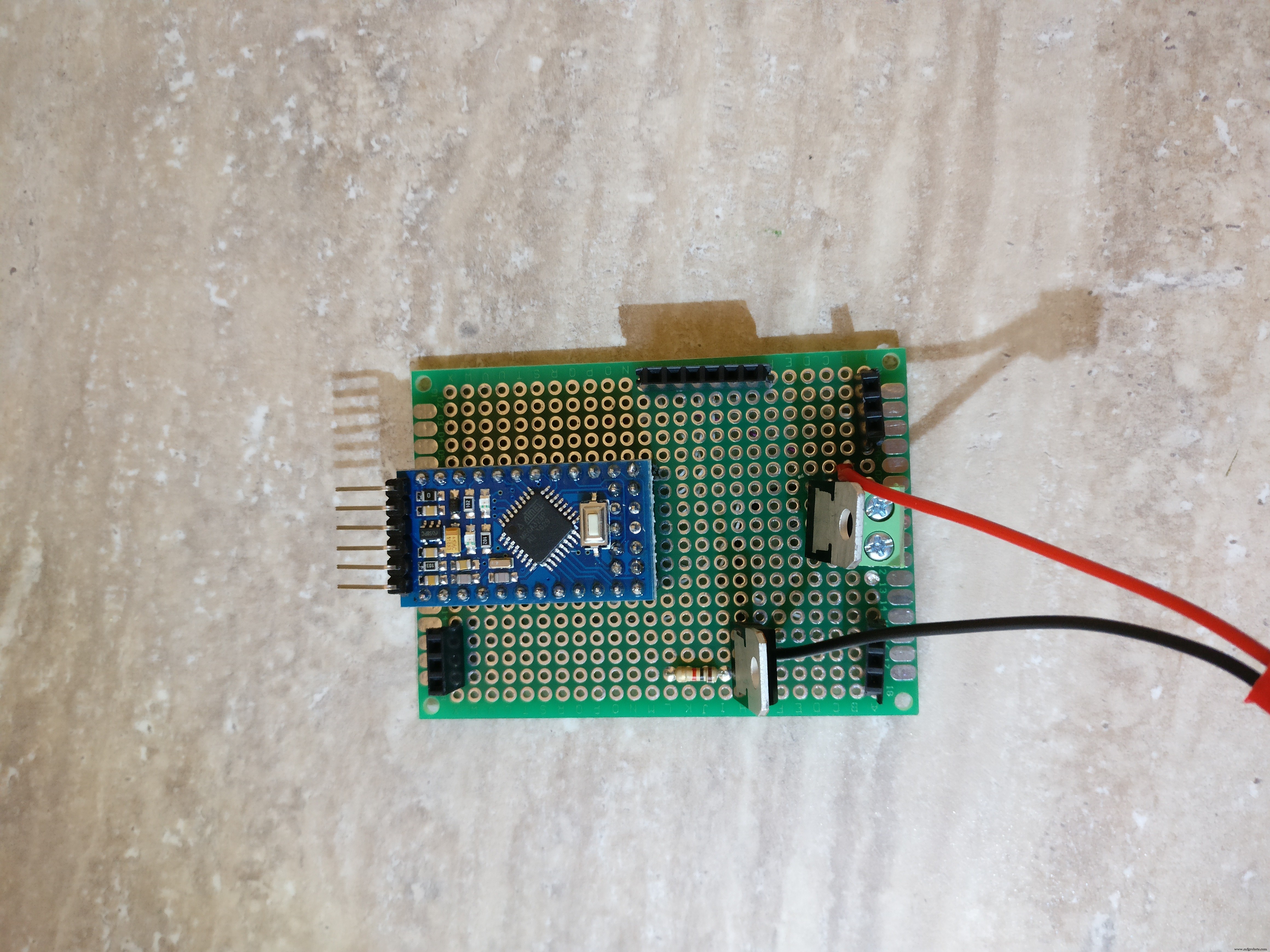
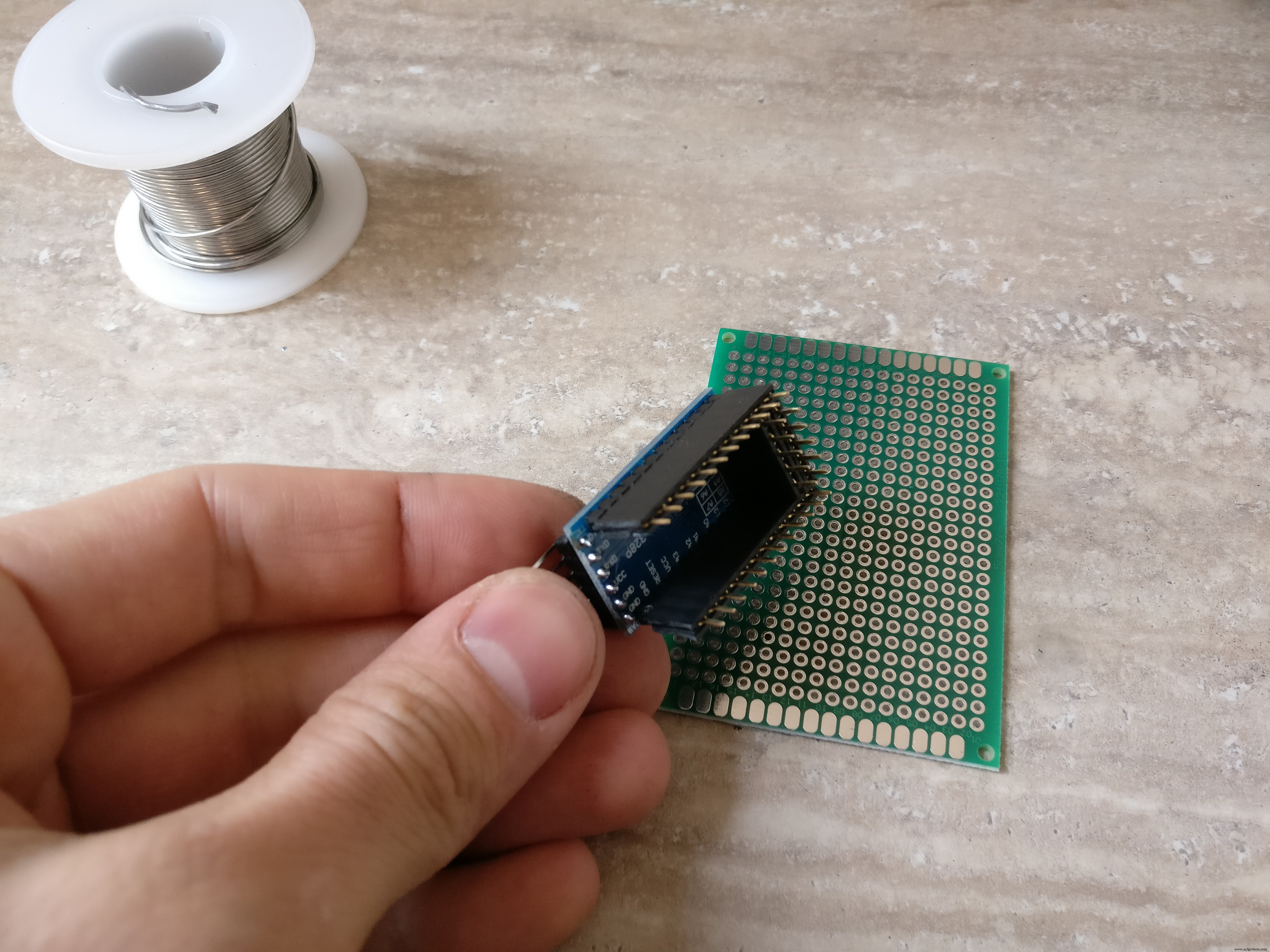
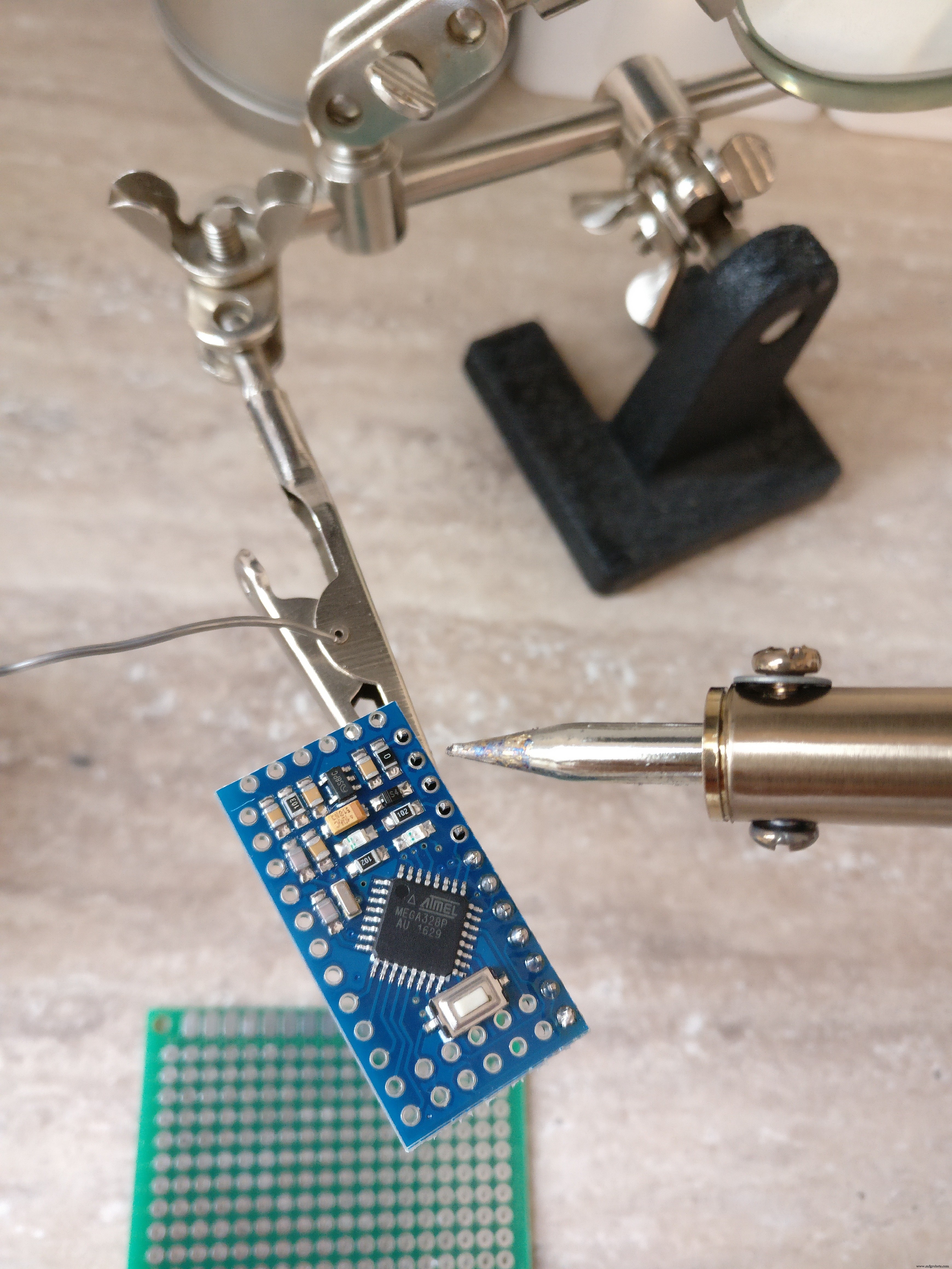
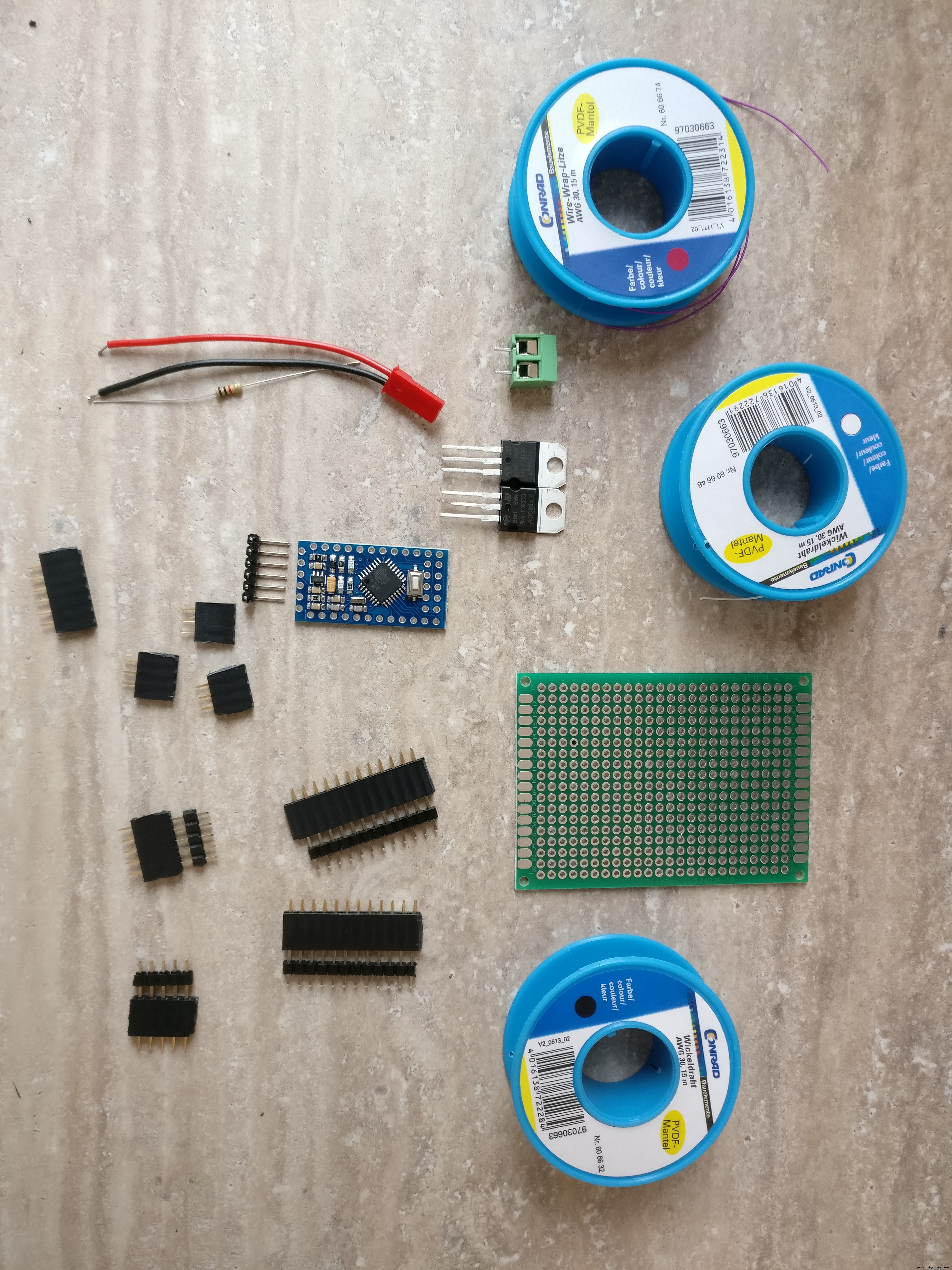
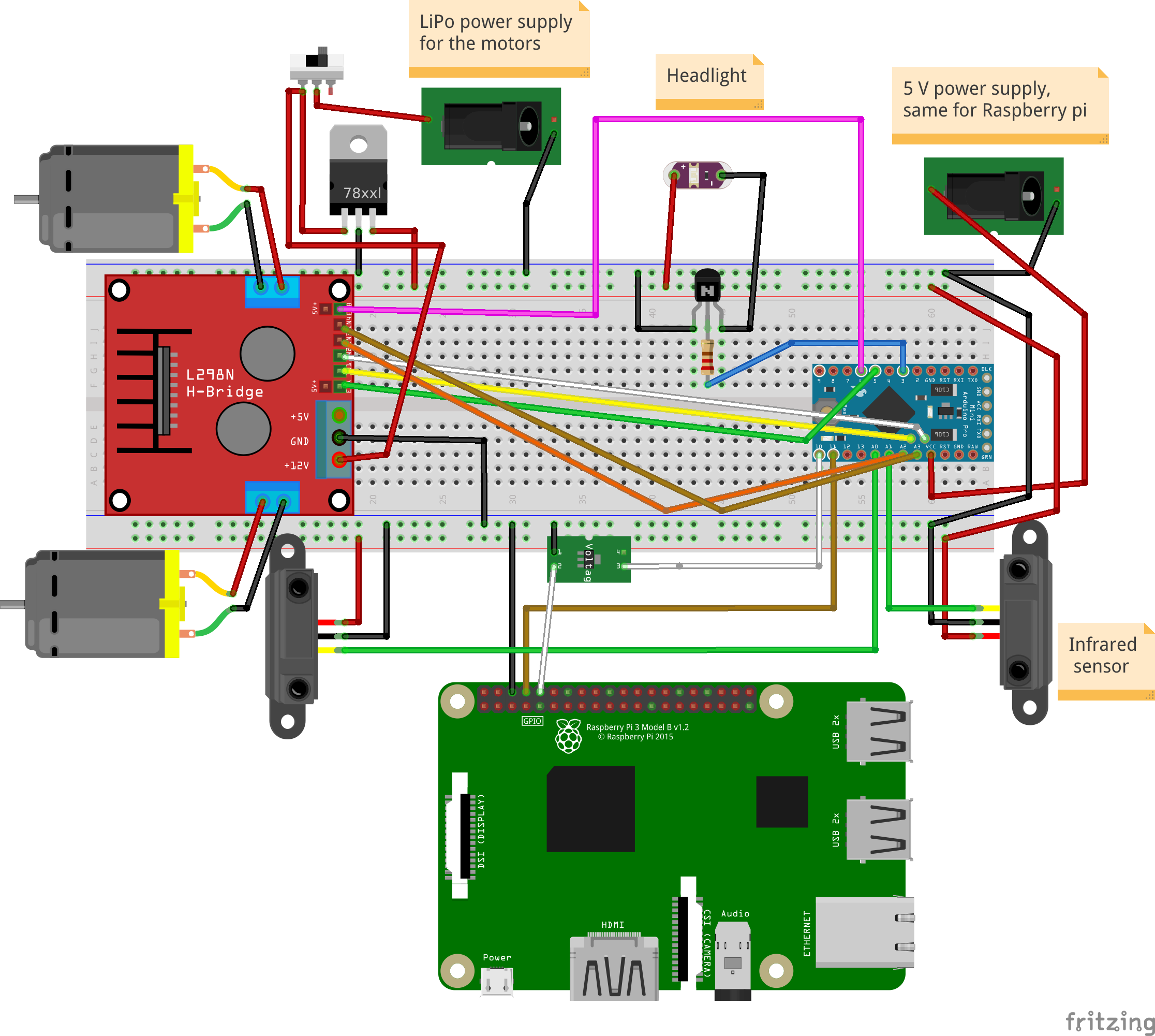
Pinout (Arduino Pro Mini)
- Hoofdlamp: D3
- Linker motor: PWM (D5), EN1, EN2 (A4, A5)
- Rechter motor: PWM (D6), EN1, EN2 (A3, A2)
- IR-sensoren: Voor (A0), Achter (A1)
- Raspberry Pi communicatie: TX → D11, RX → D10 (SoftwareSerial)
PCB-assemblage stappen
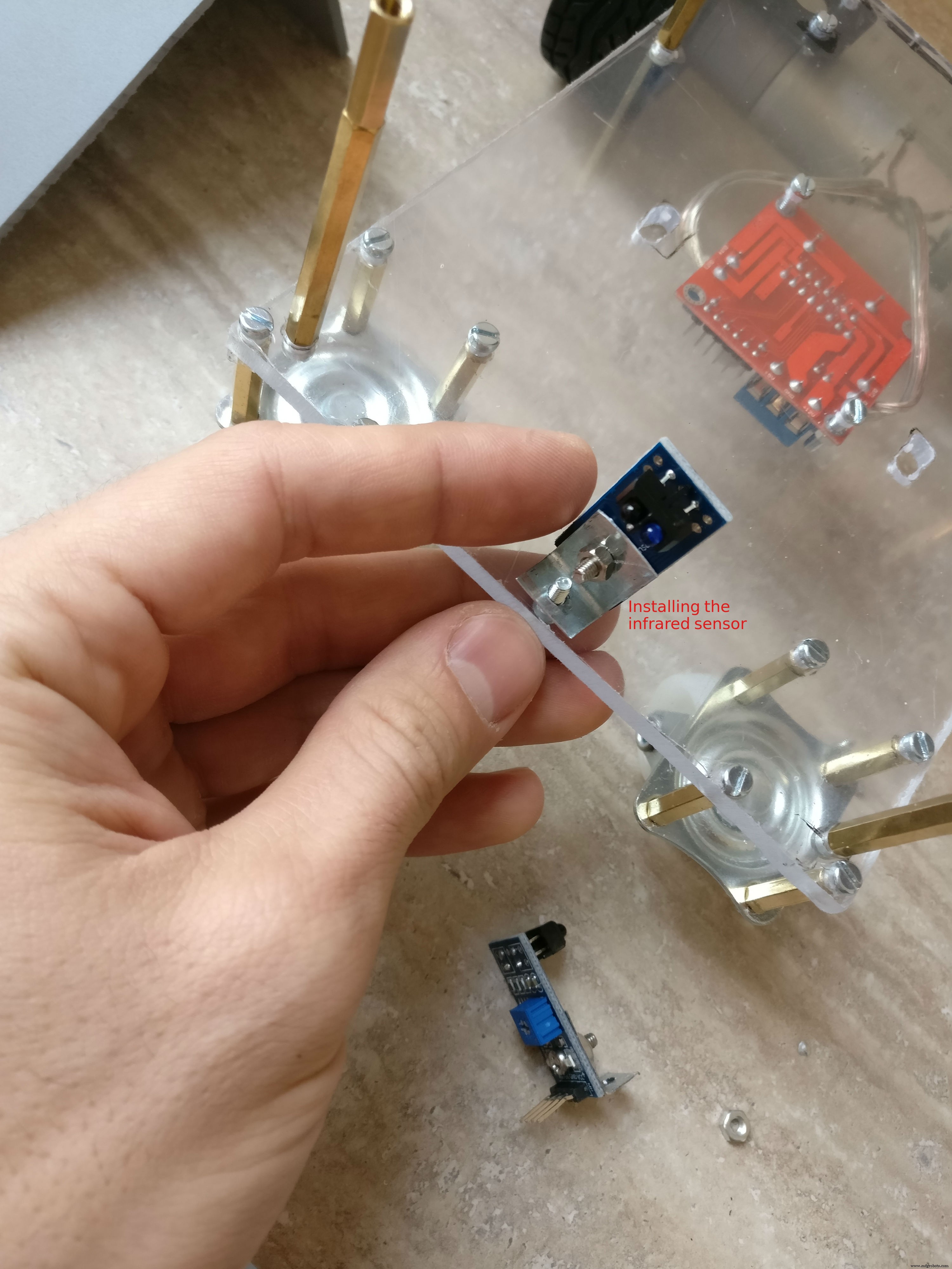
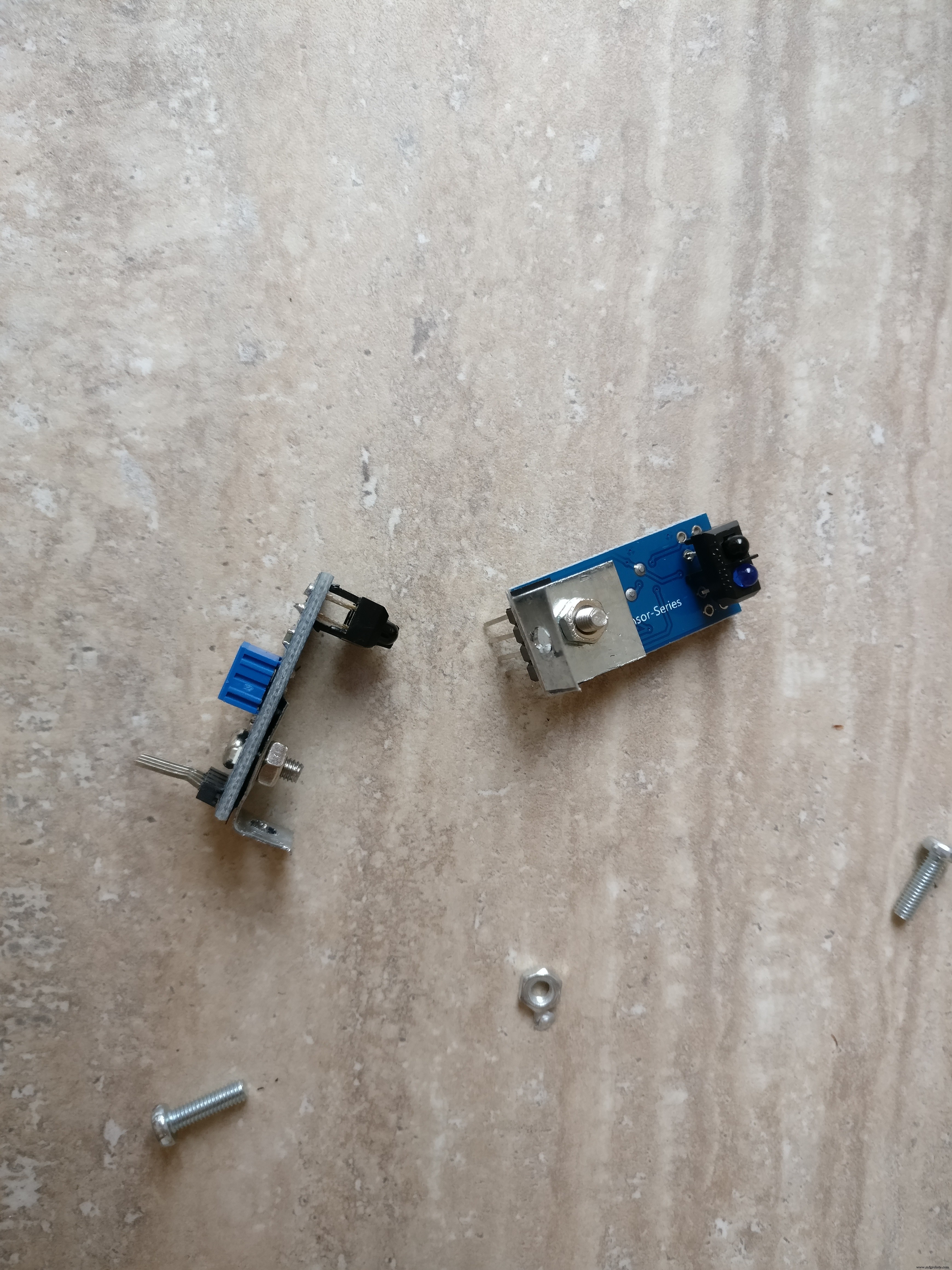
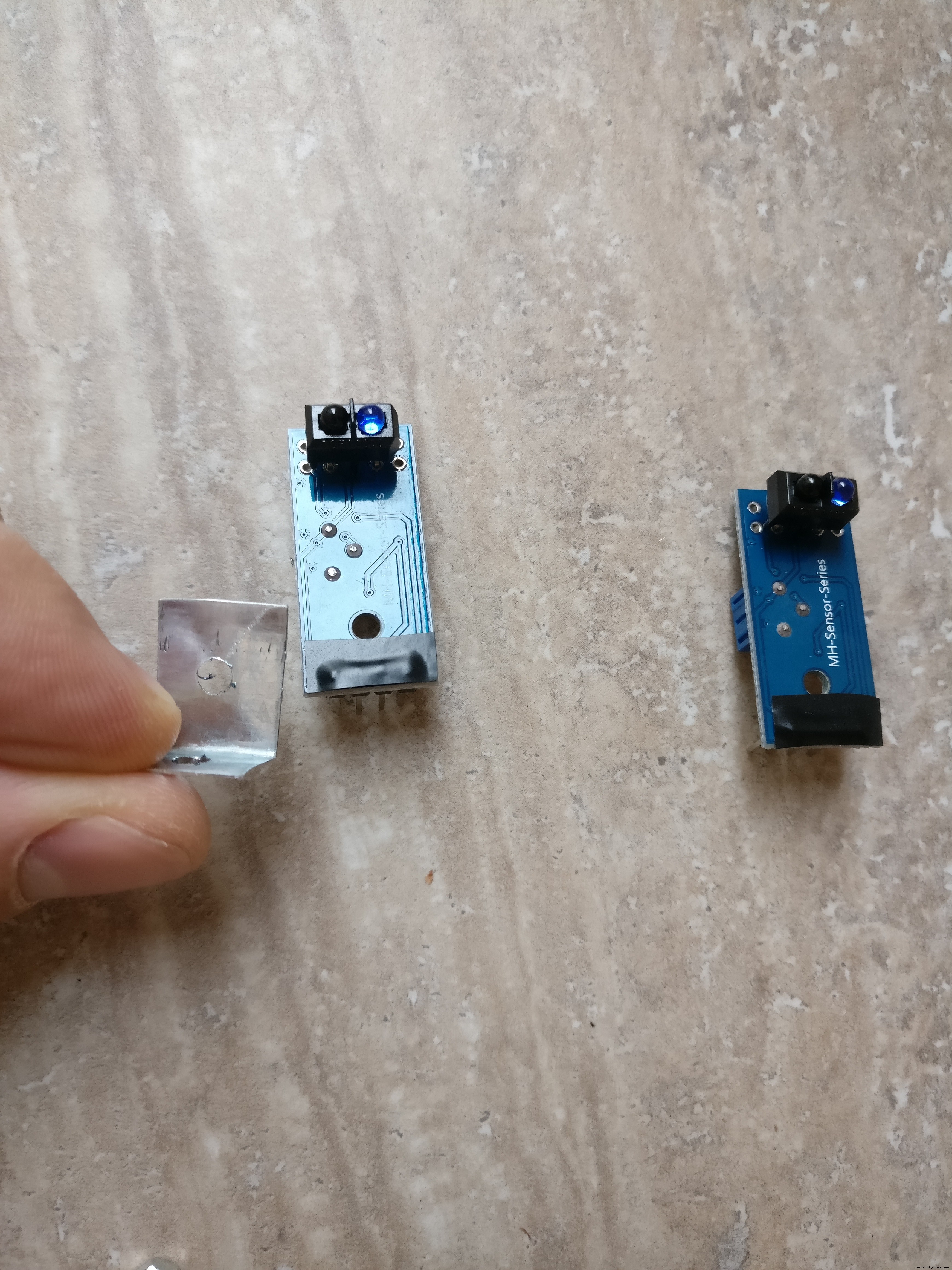
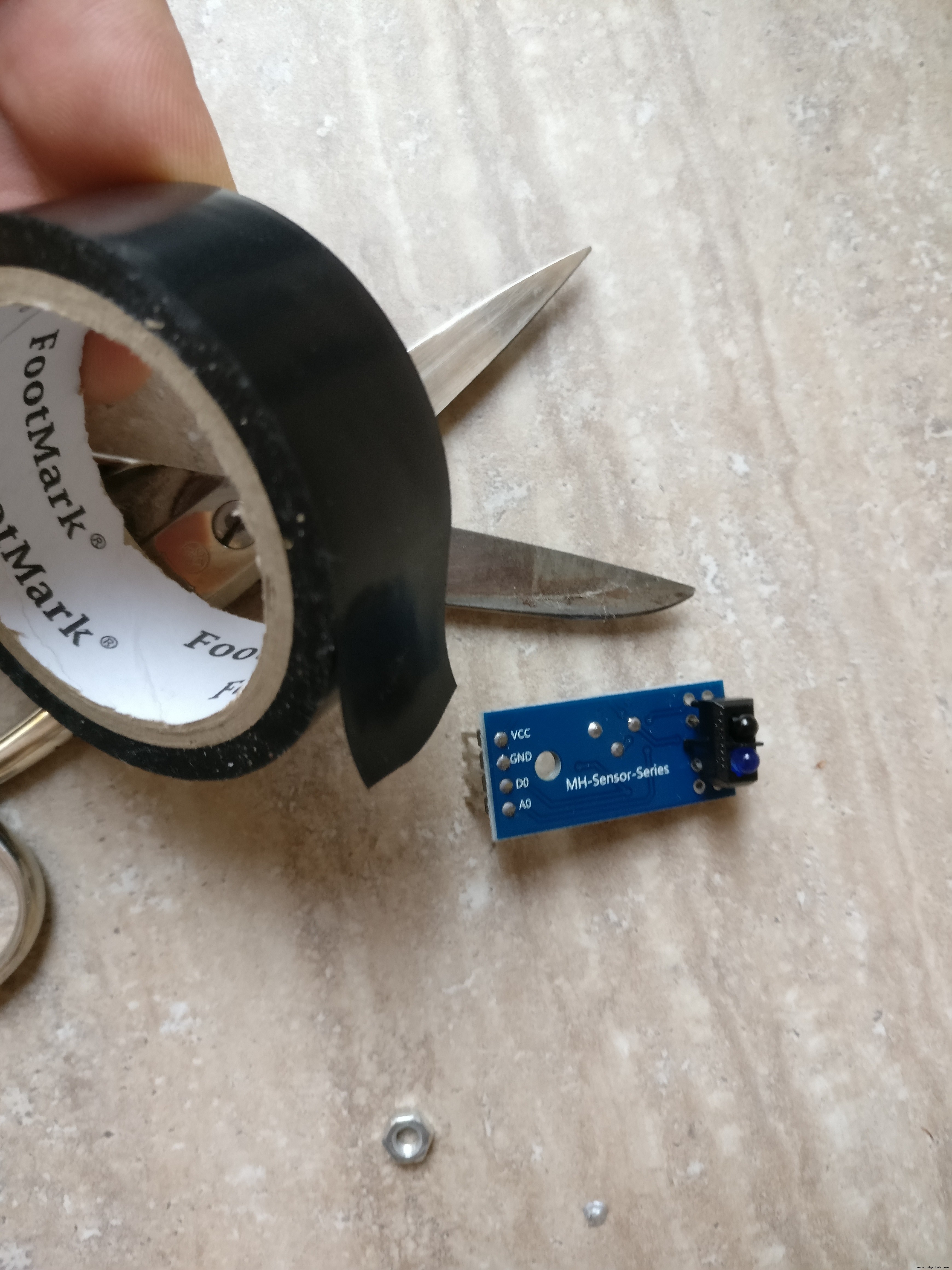
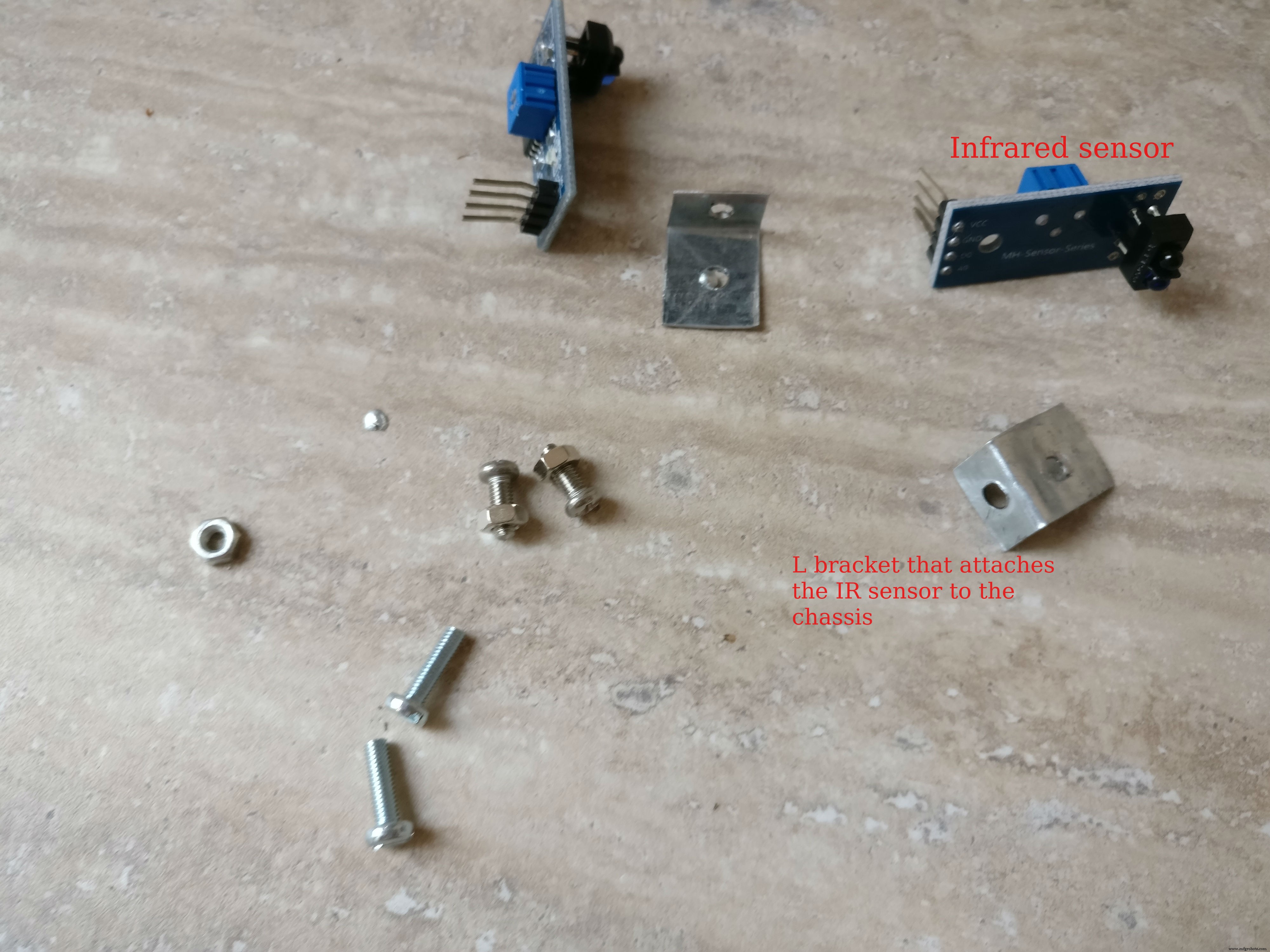
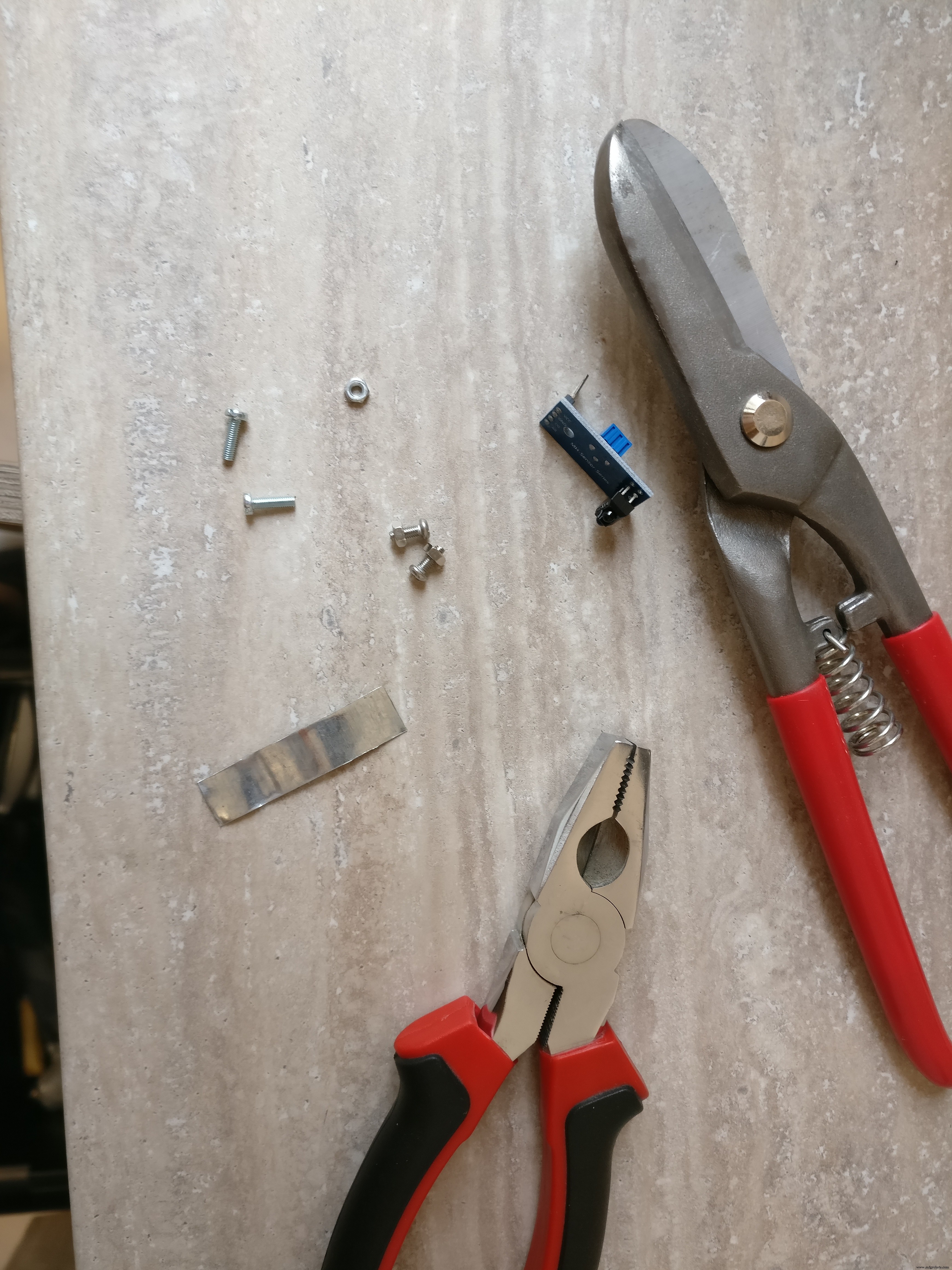
- IR-sensoren: Monteer op L-metalen plaatje (2 gaten) op chassis, één voor, één achter.
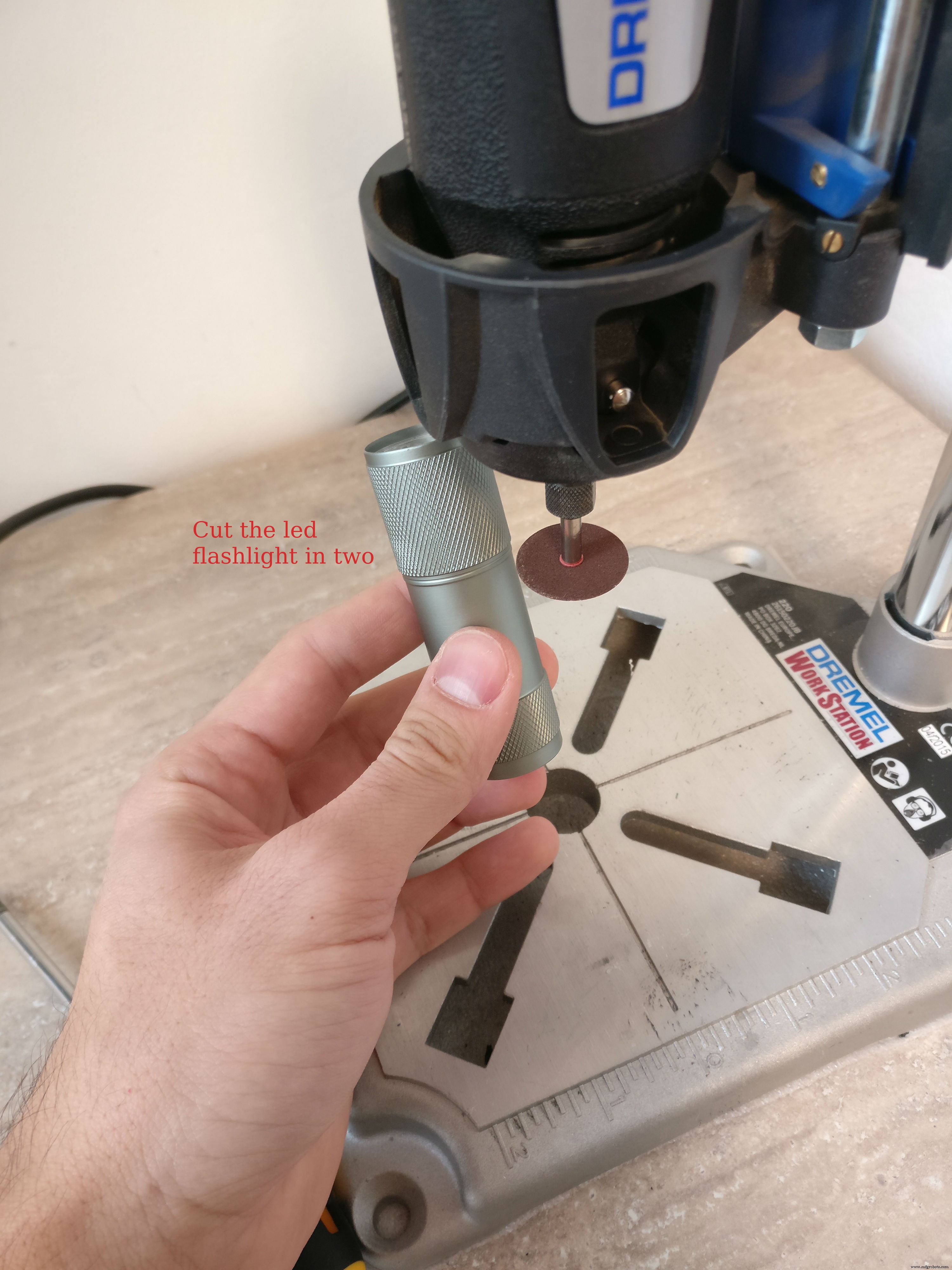
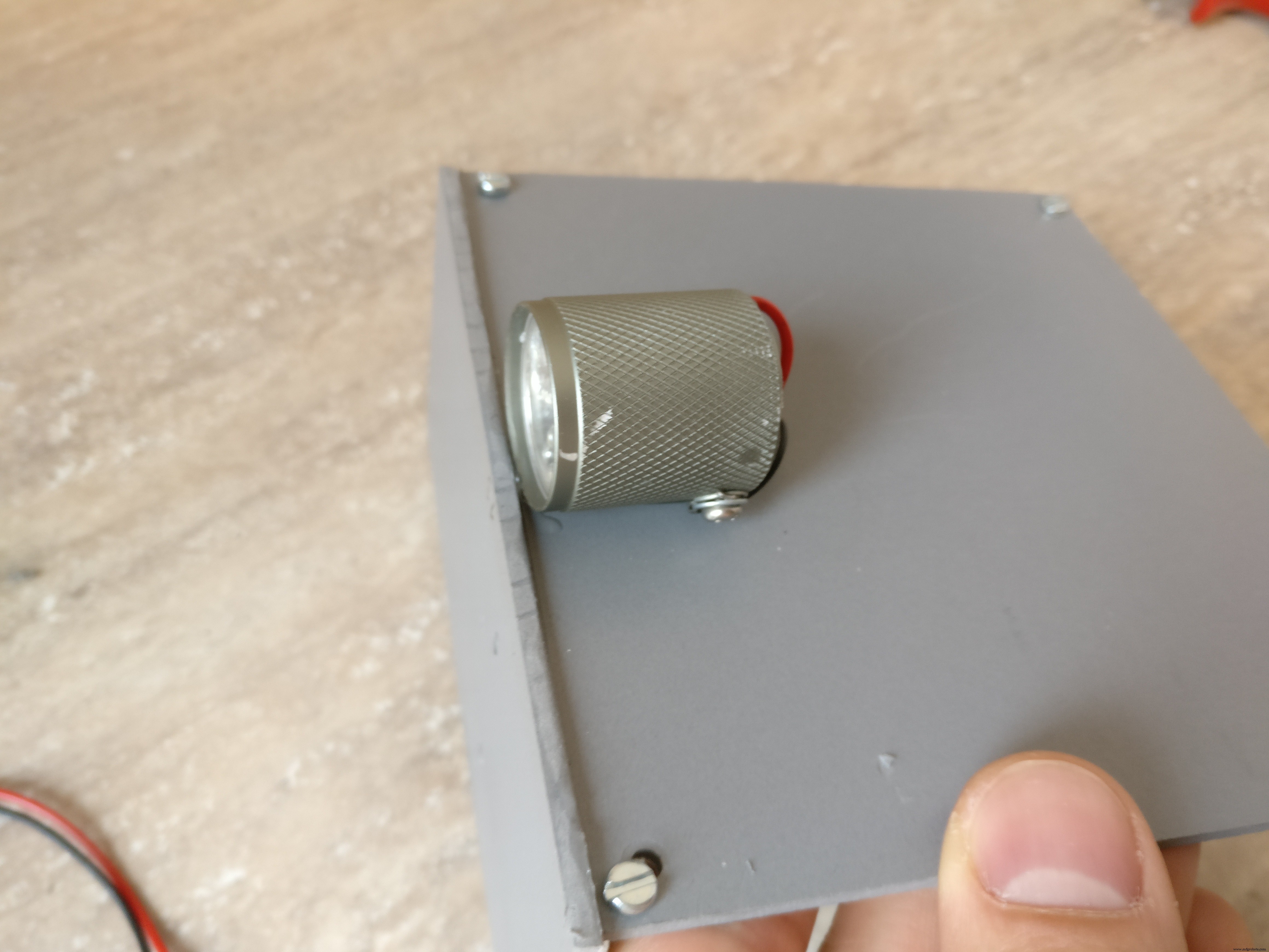
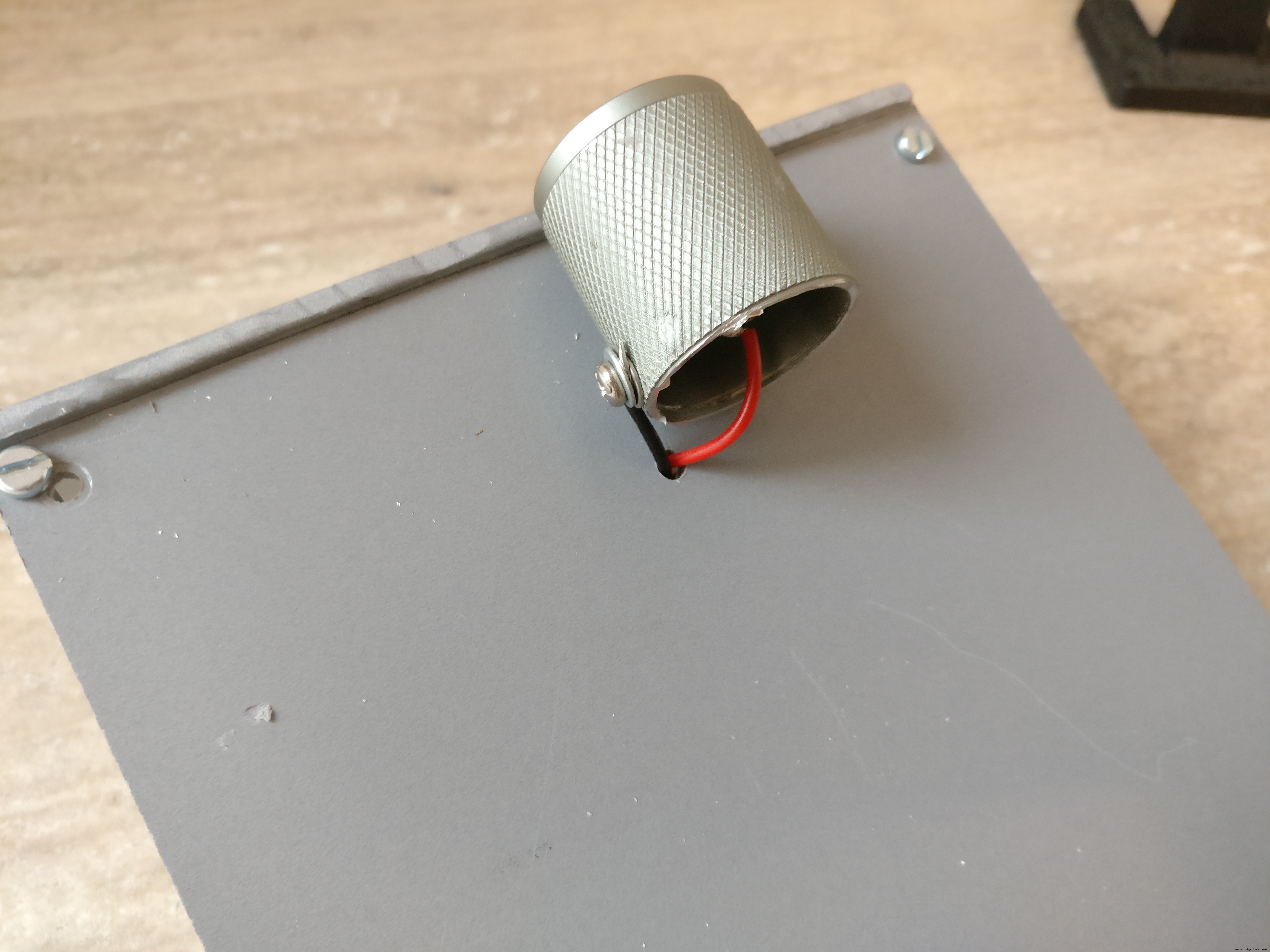
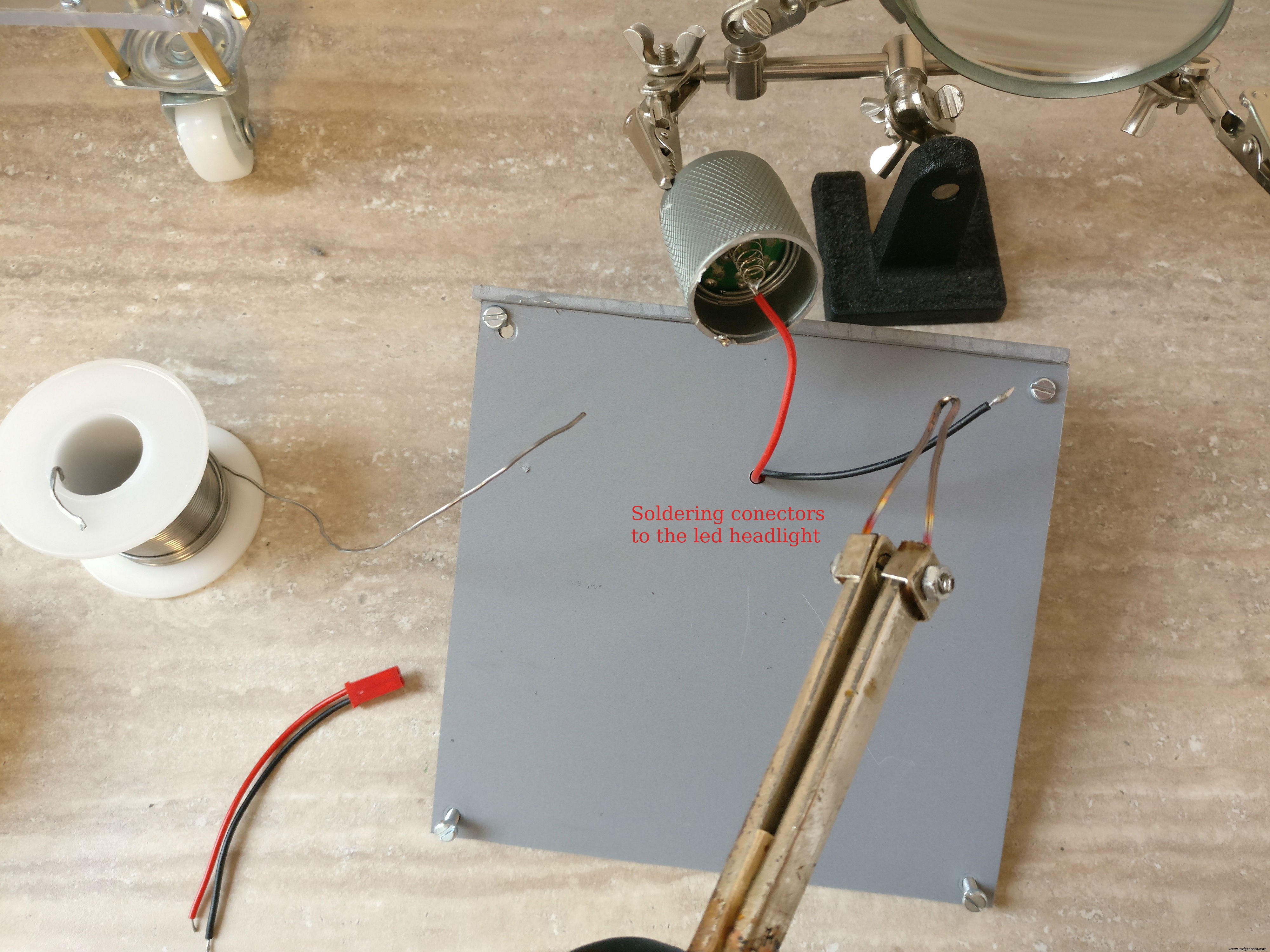
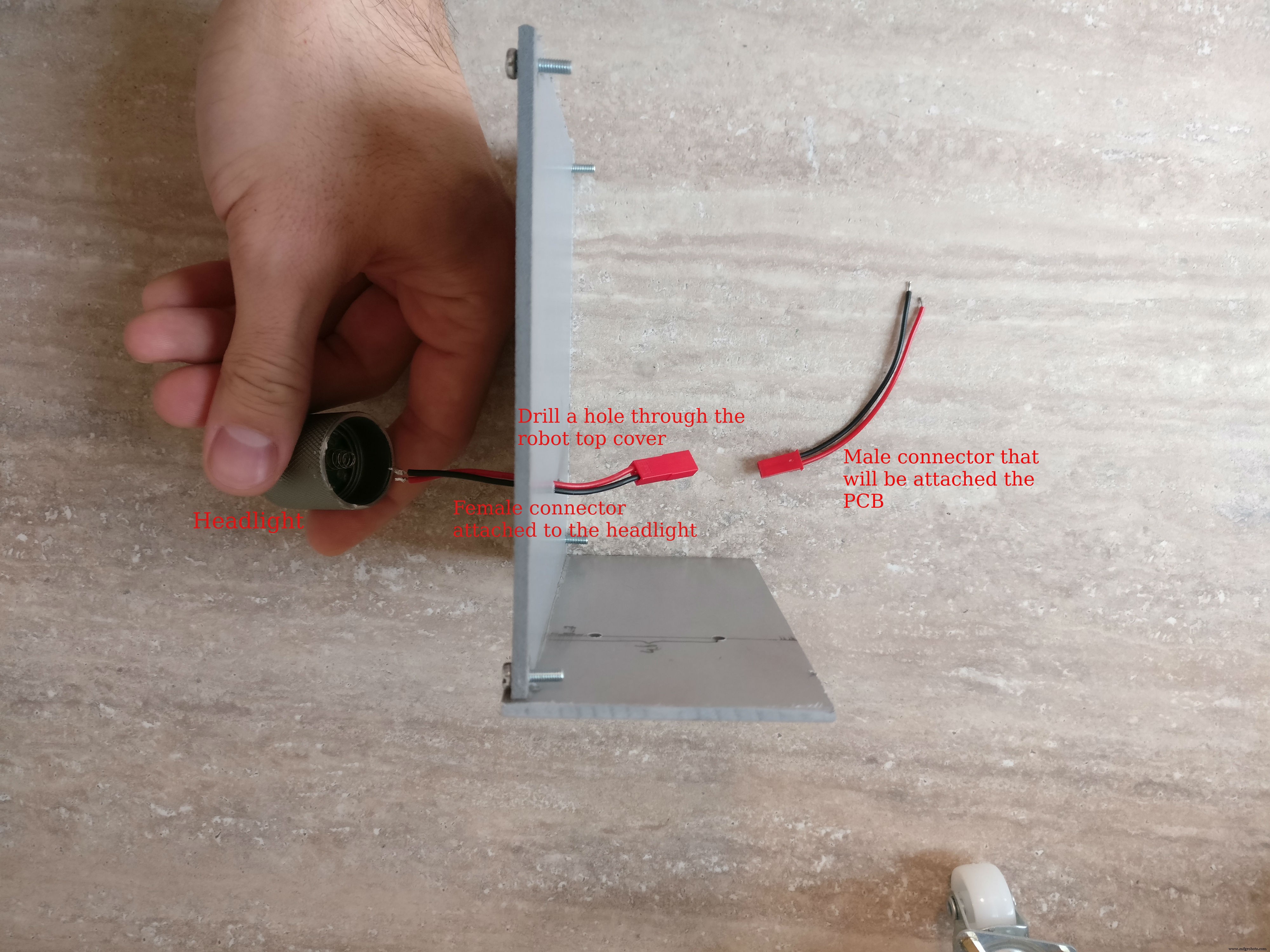
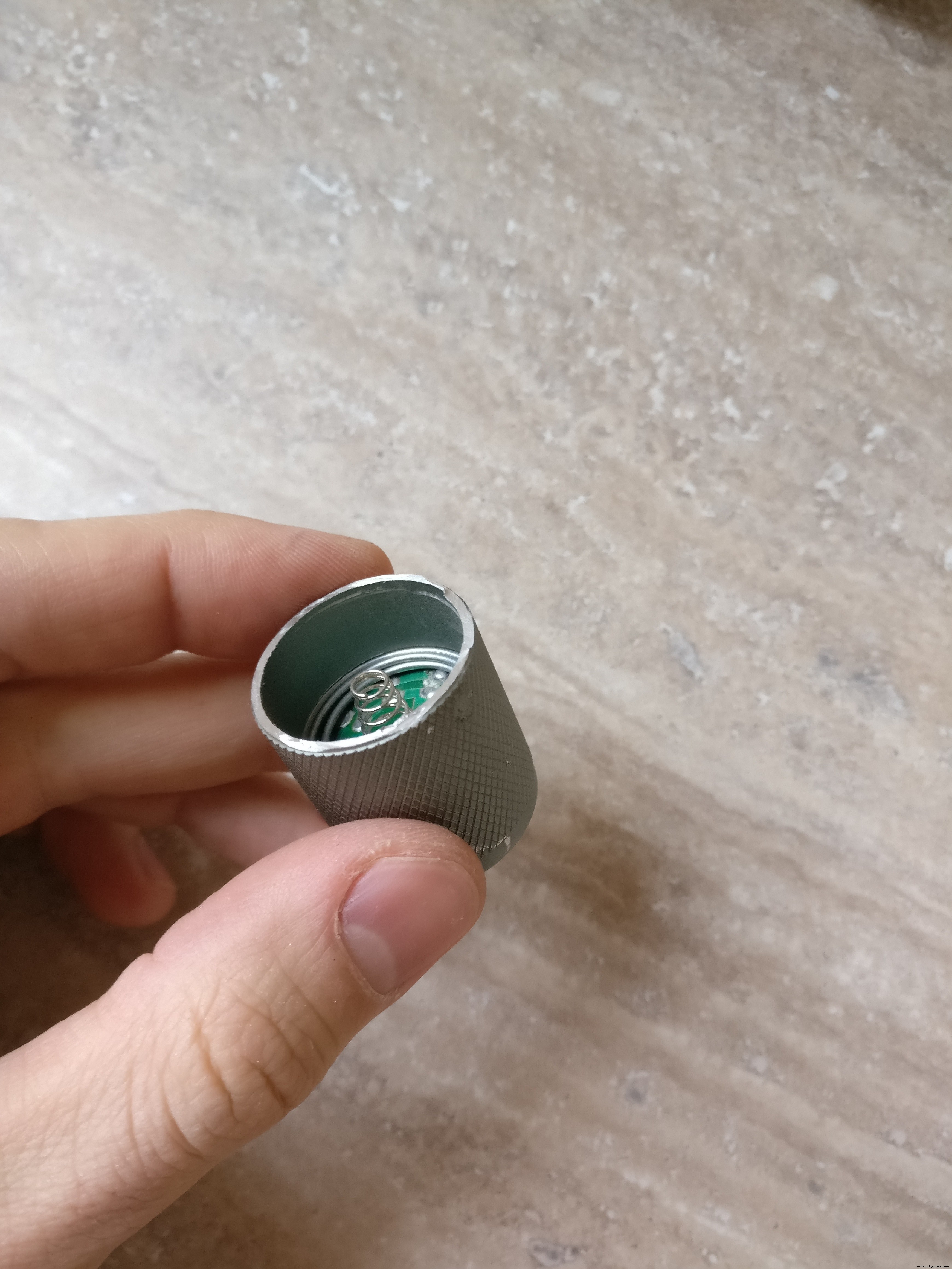
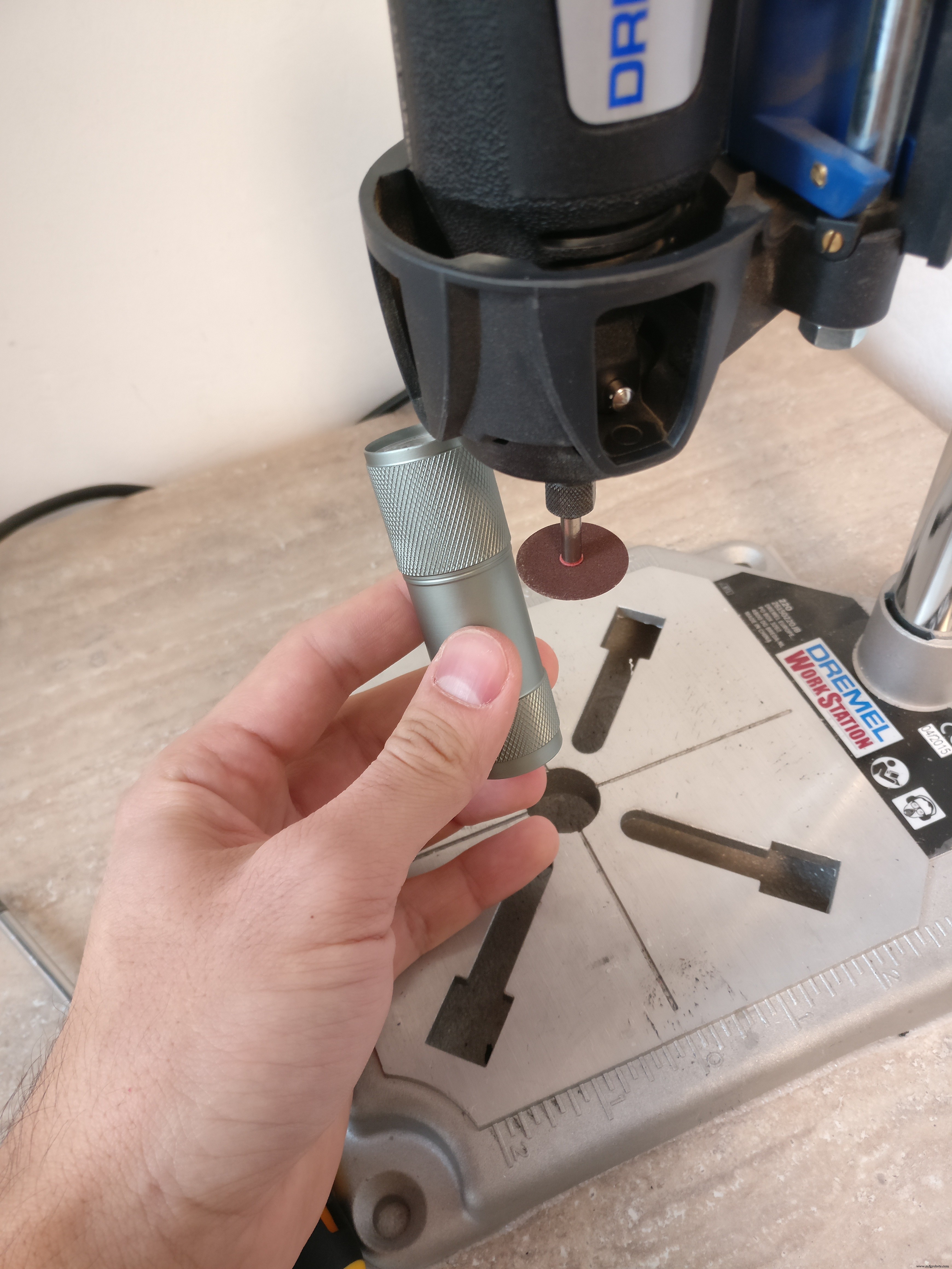
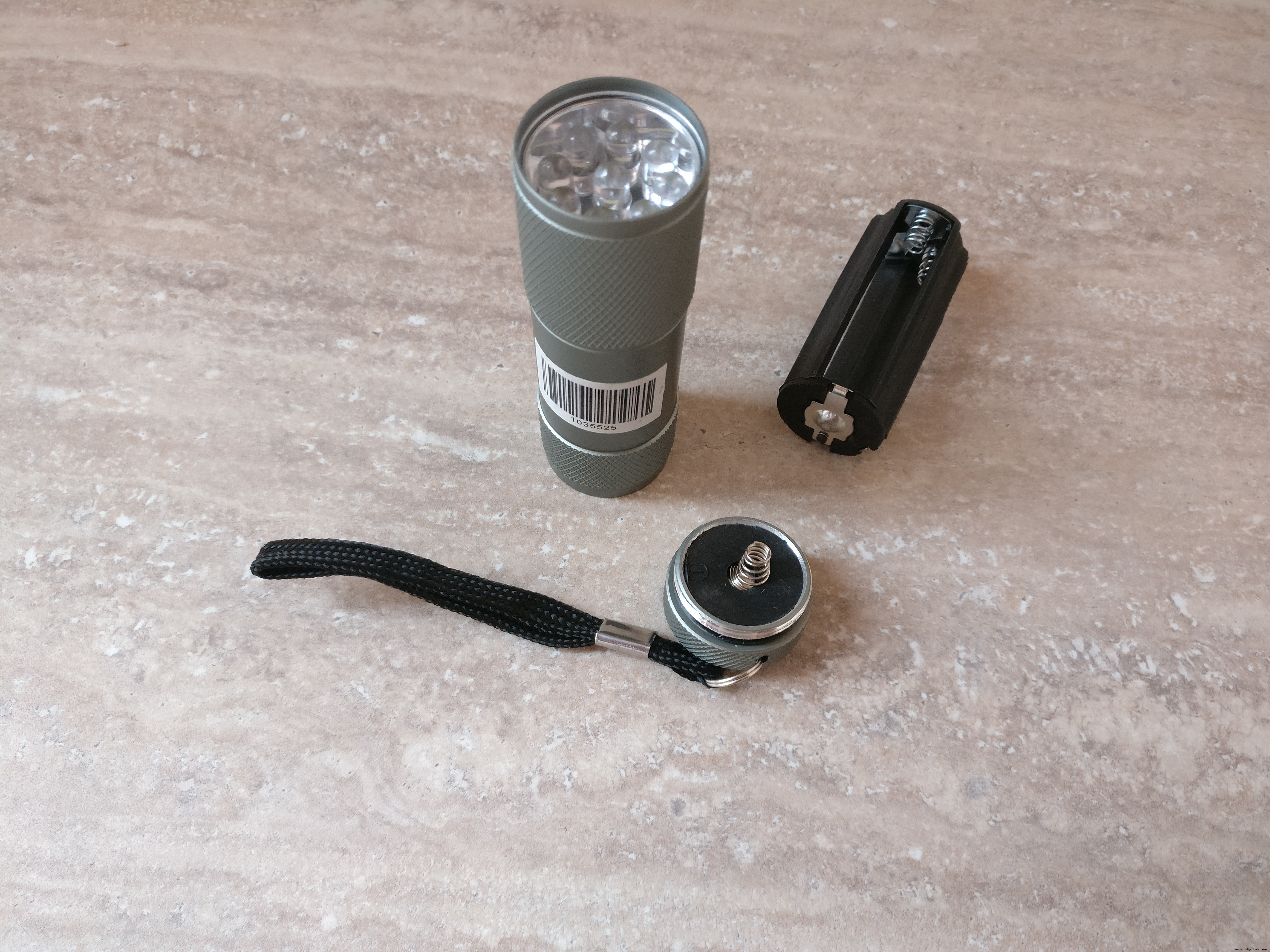
- Hoofdlamp: 5V LED-zaklamp inkorten, draden solderen, op bovenplaat lijmen, gat boren voor kabels, female connector solderen.
- Raspberry Pi behuizing: Pi + camera + SD-kaart (Raspbian) in officieel behuizing. Camera-fitting aanklikken. Zie officiële handleiding.
- Hoofd-PCB: Gebruik Fritzing-schema (bijgeleverd). Soldervolgorde:
- Female PCB-connectors knippen & solderen (2×12p voor μC, 2×5p, 2×3p voor IR, 6p voor H-brug, 3p voor Pi-comm)
- KF301-2P connector (voeding)
- NPN-transistor + basisweerstand
- L7805CV 5V regulator
- 3,3V regulator op Arduino TX → Pi RX lijn
- Male headers op Arduino Pro Mini
- Alle rode (+), zwarte (-), witte (signaal) draden per schema
- Male connector voor hoofdlicht
- Connectors bouwen:
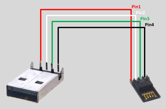
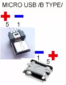
- 5V powerbank → USB-A male + Micro-USB male → Pi & Arduino (gemeenschappelijke GND/VCC)
- LiPo (XT-60) → schakelaar → KF301-2P op PCB
- IR-sensoren → female connectors op PCB
- H-brug → 6p female connector op PCB
- Motoren → H-brug
- H-brug voeding → KF301-2P
- Controleren: Voor Arduino plaatsen: multimeter + vergrootglas op alle soldeerpunten.
Stap 4: Arduino-code
Waarom een Arduino-tussenlaag?
- Modulair: Arduino herbruikbaar zonder Pi.
- Veiligheid: €3 Arduino vervangen is goedkoper dan €35 Pi.
- Real-time: Geen OS-interrupts → betrouwbare PWM & sensor-polling.
- Fail-safe: Arduino watchdog werkt altijd, ongeacht OS-crash.
- Debuggen: Ontkoppeld systeem is eenvoudiger te testen.
De sketch doet twee dingen:
- Ontvangt commando's via seriële poort (van Pi) en stuurt motoren/lamp aan.
M:-25:16;→ links -25, vermogen 16 → linker motor 17%, rechter 32%, vooruitM:44:19;→ rechts 44, vermogen 19 → linker 38%, rechter 5%, vooruitL:1;licht aan,L:0;licht uit
- Meet IR-sensoren (voor/achter) en stuurt afstandsdata terug via seriële poort.
Benodigde bibliotheek: TextMotorCommandsInterpretter.
Volledige code op GitHub of hieronder:
// TextMotorCommandsInterpretter bron: "https://github.com/danionescu0/arduino/tree/master/libraries/TextMotorCommandsInterpretter"
#include <SoftwareSerial.h>
#include <TextMotorCommandsInterpretter.h>

const char MOTOR_COMMAND = 'M';
const char LIGHT_COMMAND = 'L';
const long maxDurationForMottorCommand = 300; // ms
const byte maxPwmValue = 230;
const long transmitingInterval = 500; // ms
const int maxObstacleDetection = 1000;
const int minObstacleDetection = 500;

const byte FLASH_PIN = 3;
const byte RIGHT_MOTOR_PWM_PIN = 5;
const byte RIGHT_MOTOR_EN1_PIN = A4;
const byte RIGHT_MOTOR_EN2_PIN = A5;
const byte LEFT_MOTOR_PWM_PIN = 6;
const byte LEFT_MOTOR_EN1_PIN = A3;
const byte LEFT_MOTOR_EN2_PIN = A2;
const byte FRONT_DISTANCE_SENSOR = A0;
const byte BACK_DISTANCE_SENSOR = A1;

SoftwareSerial masterComm(11, 10); // RX, TX
TextMotorCommandsInterpretter motorCommandsInterpretter(-50, 50, -50, 50);

String currentCommand;
long lastCheckedTime;
long lastTransmitTime;
boolean inMotion = false;

void setup() {
  Serial.begin(9600);
  masterComm.begin(9600);
  masterComm.setTimeout(10);
  pinMode(FLASH_PIN, OUTPUT);
  pinMode(LEFT_MOTOR_PWM_PIN, OUTPUT);
  pinMode(LEFT_MOTOR_EN1_PIN, OUTPUT);
  pinMode(LEFT_MOTOR_EN2_PIN, OUTPUT);
  pinMode(RIGHT_MOTOR_PWM_PIN, OUTPUT);
  pinMode(RIGHT_MOTOR_EN1_PIN, OUTPUT);
  pinMode(RIGHT_MOTOR_EN2_PIN, OUTPUT);
  lastCheckedTime = millis();
  lastTransmitTime = millis();
}

void loop() {
  if (masterComm.available() > 0) {
    currentCommand = masterComm.readString();
    processCommand();
  }
  if (inMotion && millis() - lastCheckedTime > maxDurationForMottorCommand) {
    stopMotors();
  }
  if (millis() - lastTransmitTime > transmitingInterval) {
    lastTransmitTime = millis();
    masterComm.print(getObstacleData());
    Serial.print(analogRead(BACK_DISTANCE_SENSOR)); Serial.print("---");
    Serial.println(getObstacleData());
  }
}

String getObstacleData() {
  int frontDistance = analogRead(FRONT_DISTANCE_SENSOR);
  int backDistance = analogRead(BACK_DISTANCE_SENSOR);
  frontDistance = map(frontDistance, maxObstacleDetection, minObstacleDetection, 0, 10);
  backDistance = map(backDistance, maxObstacleDetection, minObstacleDetection, 0, 10);
  return String("F=" + String(frontDistance) + ":B=" + String(backDistance) + ";");
}

void processCommand() {
  switch (currentCommand.charAt(0)) {
    case MOTOR_COMMAND: steerCar(); break;
    case LIGHT_COMMAND: toggleLight(currentCommand.charAt(2)); break;
  }
}

void steerCar() {
  motorCommandsInterpretter.analizeText(currentCommand);
  float percentLeftMotor = motorCommandsInterpretter.getPercentLeft();
  float percentRightMotor = motorCommandsInterpretter.getPercentRight();
  Serial.write("Left="); Serial.println(percentLeftMotor);
  Serial.write("Right="); Serial.println(percentRightMotor);
  setMotorsDirection(motorCommandsInterpretter.getDirection());
  analogWrite(LEFT_MOTOR_PWM_PIN, percentLeftMotor * maxPwmValue);
  analogWrite(RIGHT_MOTOR_PWM_PIN, percentRightMotor * maxPwmValue);
  inMotion = true;
  lastCheckedTime = millis();
}

void setMotorsDirection(boolean forward) {
  if (forward) {
    digitalWrite(LEFT_MOTOR_EN1_PIN, HIGH);
    digitalWrite(LEFT_MOTOR_EN2_PIN, LOW);
    digitalWrite(RIGHT_MOTOR_EN1_PIN, HIGH);
    digitalWrite(RIGHT_MOTOR_EN2_PIN, LOW);
  } else {
    digitalWrite(LEFT_MOTOR_EN1_PIN, LOW);
    digitalWrite(LEFT_MOTOR_EN2_PIN, HIGH);
    digitalWrite(RIGHT_MOTOR_EN1_PIN, LOW);
    digitalWrite(RIGHT_MOTOR_EN2_PIN, HIGH);
  }
}

void stopMotors() {
  Serial.println("Stopping motors");
  analogWrite(LEFT_MOTOR_PWM_PIN, 0);
  analogWrite(RIGHT_MOTOR_PWM_PIN, 0);
  inMotion = false;
}

void toggleLight(char command) {
  Serial.println("Toggle light");
  if (command == '1') digitalWrite(FLASH_PIN, HIGH);
  else digitalWrite(FLASH_PIN, LOW);
}
Stap 5: Raspberry Pi project & dependencies
Architectuur
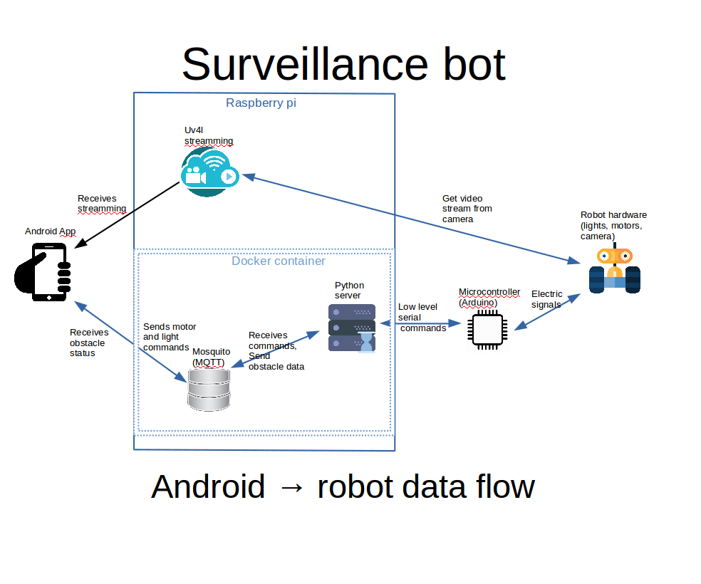
- Android-app toont uv4l-stream in WebView.
- uv4l op Pi: camera-capture & streaming.
- Besturing via app → MQTT-server (Mosquitto).
- Python-server in Docker luistert naar MQTT, stuurt seriële commando's naar Arduino.
- Arduino stuurt sensordata terug → Python → MQTT → app.
Vereisten
- Raspbian geïnstalleerd, camera ingeschakeld, SSH actief.
- Poortforwarding op router voor externe toegang: 9090 (uv4l), 1883 (Mosquitto).
- Lokaal IP van Pi:
ifconfig→ wlan0 inet addr.
Installatie stappen
git clone https://github.com/danionescu0/robot-camera-platform.gitin/home/pi(hardcoded in docker-compose.yml).- Pi seriële console uitschakelen (handleiding).
- uv4l installeren:
Configureer inchmod +x uv4l/install.sh uv4l/start.sh sh ./uv4l/install.shuv4l/start.sh: wachtwoord, poort, framerate, resolutie, rotatie. - Configuratie:
config.py: MQTT-wachtwoord, seriële poort (/dev/ttyS0), baudrate (9600).docker-container/mosquitto/Dockerfile:RUN mosquitto_passwd -b /etc/mosquitto/pwfile user jouw_wachtwoord
- Test uv4l:
sh ./uv4l/start.sh→ browser:https://IP_PI:9090/stream→sudo pkill uv4l. - Docker & Docker Compose installeren: Raspberry Pi blog.
- Auto-start met systemd:
cp systemctl/* /etc/systemd/system/
sudo systemctl enable robot-camera.service
sudo systemctl enable robot-camera-video.service
reboot
# Check:
sudo systemctl status robot-camera.service
sudo systemctl status robot-camera-video.service
Stap 6: Android-applicatie
git clone https://github.com/danionescu0/android-robot-camera- Developer options inschakelen op telefoon.
- Android Studio installeren + Java.
- Project importeren.
./app/src/main/res/values/passwords.xmlaanpassen: MQTT-host/poort, streaming-URL.- App bouwen & draaien op telefoon.
Stap 7: Gebruiken & Debuggen
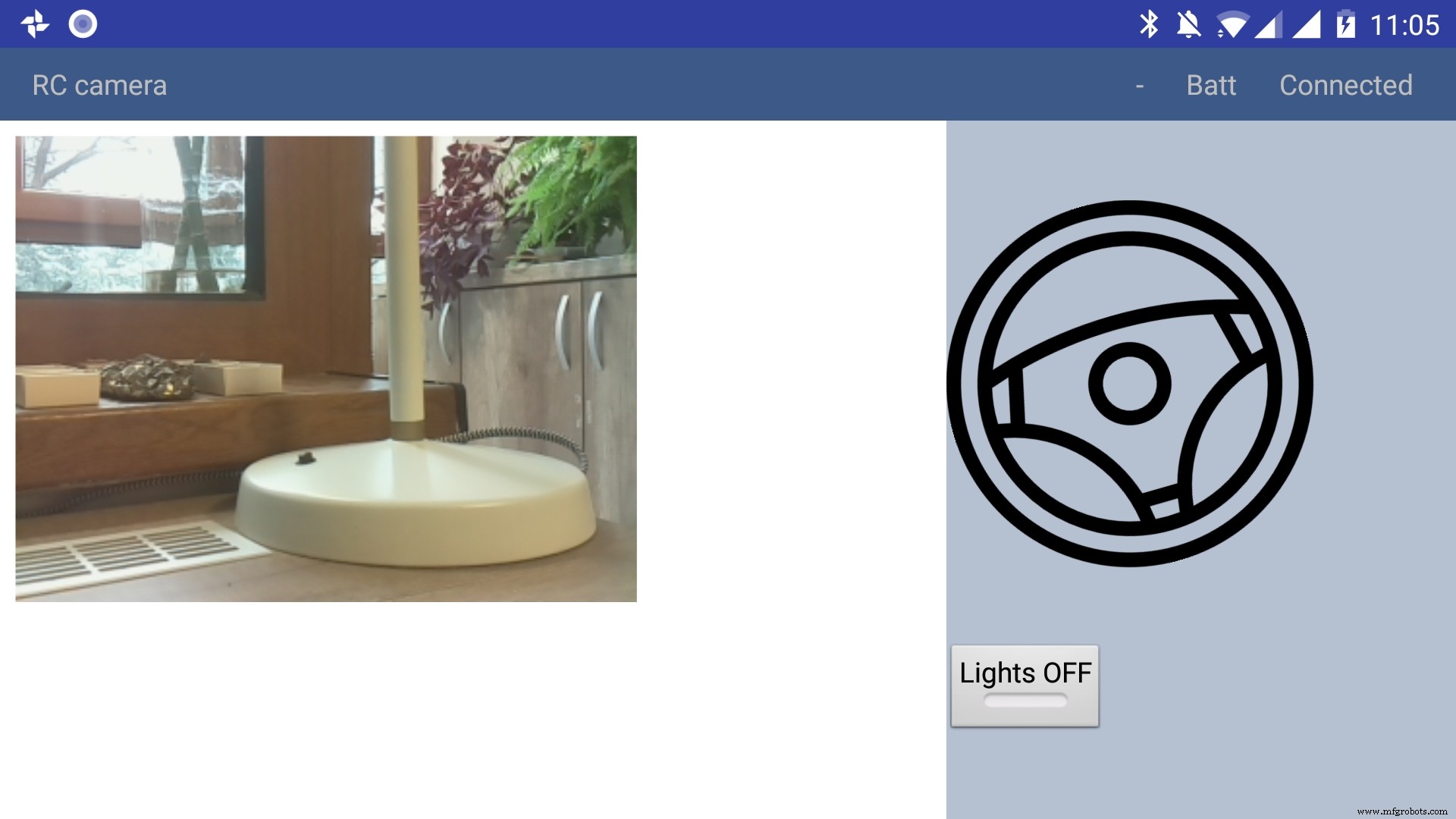
App-bediening
- Links: videostream (uv4l).
- Rechts: besturing – stuurwiel (aanraken voor richting), hoofdlicht-knop.
- Boven rechts: status – bijv.
- Batt Connected.- Eerste teken:
-= geen obstakel, pijltje = obstakel voor/achter. Batt= nog niet geïmplementeerd.Connected= MQTT verbonden; andersDisconnected.
- Eerste teken:
Debug-lagen
- Arduino-laag: FTDI adapter op 2e seriële lijn (RX↔D11, TX↔D10). Test commando's handmatig. Check motorrichting (draden omdraaien indien nodig).
- Raspberry Pi-laag:
docker ps→ 2 containers (mosquitto, python-server) draaien?netstat -nltp→ poorten 9090 (stream), 1883 (MQTT) luisteren?ls -l /dev/ttyS0→ seriële poort bestaat?- Docker stoppen, handmatig testen:
sudo systemctl stop robot-camera.service && picocom -b 9600 /dev/ttyS0→ stuur commando's. - Seriële console uitgeschakeld op Pi?
- Stream & MQTT bereikbaar van buitenaf?
- Android-laag:
- USB-debugging aan?
passwords.xmlcorrect?- Stream/MQTT bereikbaar?
- App status "Connected"?
- Android debugger voor errors.
Stap 8: Uitbreidingen
Object-volgende robot: Kleurdetectie via OpenCV (HSV-drempels).
sudo pip3 install -r /home/pi/robot-camera-platform/navigation/requirements.txt
# In navigation/config_navigation.py:
hsv_bounds = ((24, 86, 6), (77, 255, 255))
object_size_threshold = (10, 100)
VNC installeren voor GUI. Draai:
python3 object_tracking.py colored-object --show-video
# of zonder video:
python3 object_tracking.py colored-object
Ideeën voor uitbreiding: gezichtsherkenning, patrouille & melding, 3G/4G modem voor buitenbereik.
Vragen? Laat een reactie achter. Abonneer op mijn YouTube-kanaal voor meer projecten!
Code repositories
Schema's
Productieproces
- De Evolutie en Ontwerp van Moderne Camera's
- Cameraobjectieven Begrijpen: Ontwerp, Geschiedenis en Toekomstige Innovaties
- MrRobot: Ubuntu Mobiel-Gestuurde Rapiro Robot met Stem, Touch & Schud Interactie
- Roomberry: Een Roomba-aangedreven Surveillance Robot Bouwen met Raspberry Pi Zero W
- Bluetooth-gestuurde Arduino gemotoriseerde camerashuif voor soepel filmische opnames
- Interactieve gyroscoop LED-display met NeoPixel-ring en Arduino
- Universele Android-afstandsbediening bouwen met Arduino, 1Sheeld en IR-besturing
- DIY Arduino USB Gaming Controller – Bouw Je Eigen High-Performance Gamepad
- Pixie: Een Arduino-gebaseerde NeoPixel-polshorloge – Modern, DIY LED-tijdstuk
- Spraakherkenning & Synthese Meesteren op Arduino Due
- Arduino PowerPoint Pointer – Draadloze Presentatiebesturing