


Arduino Robot Car Wireless Control met behulp van HC-05 Bluetooth, NRF24L01 en HC-12 Transceiver Modules
In deze tutorial zullen we leren hoe we de Arduino robotauto die we in de vorige video hebben gemaakt, draadloos kunnen besturen. Ik zal je drie verschillende methoden van draadloze bediening laten zien, met behulp van de HC-05 Bluetooth-module, de NRF24L01-zendontvangermodule en de HC-12 lange afstand draadloze module, evenals met behulp van een smartphone en een op maat gemaakte Android-applicatie. Je kunt de volgende video bekijken of de schriftelijke tutorial hieronder lezen voor meer details.
Ik heb al tutorials over het aansluiten en gebruiken van elk van deze modules met het Arduino-bord, dus als je meer details nodig hebt, kun je ze altijd controleren. De links naar elk van hen vindt u hieronder in het artikel.
Arduino Robot Car Control met HC-05 Bluetooth-module
We beginnen met de Bluetooth-communicatie en daarvoor hebben we twee HC-05 Bluetooth-modules nodig die moeten worden geconfigureerd als master- en slave-apparaten.
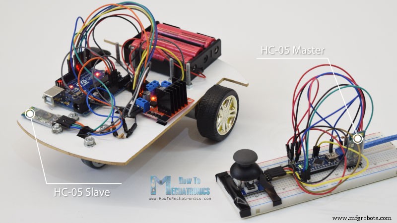
We kunnen dat gemakkelijk doen door AT-commando's te gebruiken, en ik heb de joystick ingesteld als een meester en de Arduino-robotauto als een slaaf. Hier is het volledige schakelschema voor dit voorbeeld:
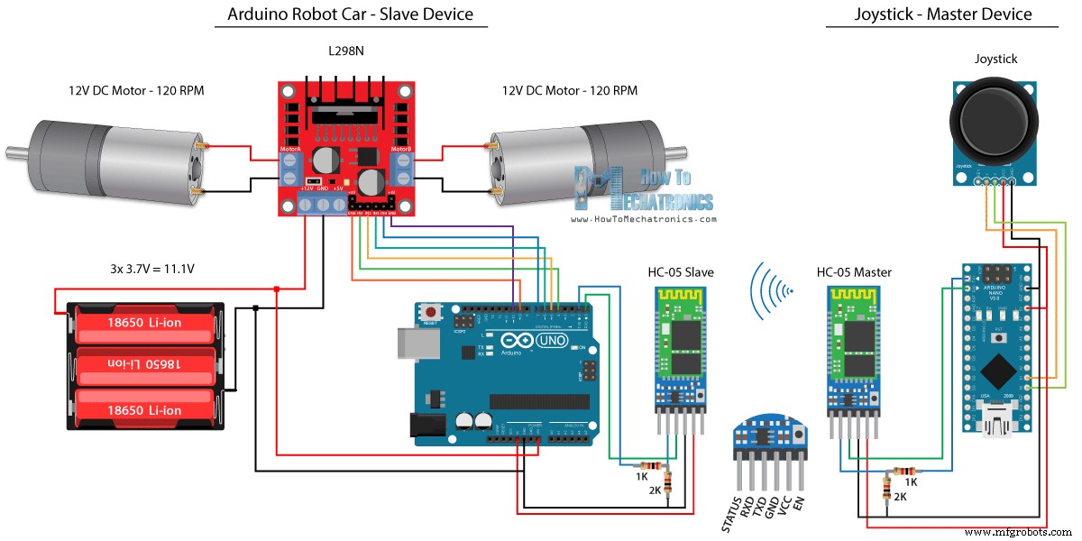
U kunt de benodigde componenten voor dit voorbeeld vinden via de onderstaande links:
- HC-05 Bluetooth-module ………….…
- Joystick-module ……………………….
- 18650 Batterijen ………………………..
- 18650 batterijlader………………
- L298N-stuurprogramma …………………………..
- 12V DC-motor met hoog koppel …………
- Arduino-bord …………………………
Broncode
We zullen dezelfde code gebruiken uit de vorige tutorial, waar we de Arduino-robotauto rechtstreeks met de joystick besturen, en we zullen er enkele wijzigingen in aanbrengen.
HC-05 Mastercode:
/*
   Arduino Robot Car Wireless Control using the HC-05 Bluetooth

                == MASTER DEVICE - Joystick ==

   by Dejan Nedelkovski, www.HowToMechatronics.com
*/

int xAxis, yAxis;

void setup() {
  Serial.begin(38400); // Default communication rate of the Bluetooth module
}

void loop() {
  xAxis = analogRead(A0); // Read Joysticks X-axis
  yAxis = analogRead(A1); // Read Joysticks Y-axis

  // Send the values via the serial port to the slave HC-05 Bluetooth device
  Serial.write(xAxis/4); // Dividing by 4 for converting from 0 - 1023 to 0 - 256, (1 byte) range
  Serial.write(yAxis/4);
  delay(20);
}Code language: Arduino (arduino)
De code op het master-apparaat of de joystick is vrij eenvoudig. We hoeven alleen de X- en Y-waarden van de joystick, die de snelheid van de motoren regelt, uit te lezen en deze via de seriële poort naar het slave HC-05 Bluetooth-apparaat te sturen. We kunnen hier opmerken dat de analoge waarden van joystick van 0 tot 1023 worden omgezet in waarden van 0 tot 255 door ze met 4 te duiken.
We doen dit omdat dat bereik, van 0 tot 255, via het Bluetooth-apparaat kan worden verzonden als 1 byte, wat gemakkelijker te accepteren is aan de andere kant, of bij de Arduino-robotauto.
Dus hier, als de serie de 2 bytes, de X- en Y-waarden heeft ontvangen, zullen we ze beide lezen met de functie Serial.read() .
// Code from the Arduino Robot Car

// Read the incoming data from the Joystick, or the master Bluetooth device
  while (Serial.available() >= 2) {
    x = Serial.read();
    delay(10);
    y = Serial.read();
  }Code language: Arduino (arduino)
Nu hoeven we alleen nog de waarden weer om te zetten naar het bereik van 0 tot 1023, geschikt voor de motorbesturingscode hieronder, waarvan we in de vorige video al hebben uitgelegd hoe het werkt.
// Code from the Arduino Robot Car

// Convert back the 0 - 255 range to 0 - 1023, suitable for motor control code below
xAxis = x*4;
yAxis = y*4;Code language: Arduino (arduino)
Even een korte opmerking dat we bij het uploaden van de code de RX- en TX-pinnen van het Arduino-bord moeten loskoppelen.
Volledige HC-05 Slave-code:
/*
   Arduino Robot Car Wireless Control using the HC-05 Bluetooth

             == SLAVE DEVICE - Arduino robot car ==

   by Dejan Nedelkovski, www.HowToMechatronics.com
*/

#define enA 9
#define in1 4
#define in2 5
#define enB 10
#define in3 6
#define in4 7

int xAxis, yAxis;
unsigned int  x = 0;
unsigned int  y = 0;

int motorSpeedA = 0;
int motorSpeedB = 0;

void setup() {
  pinMode(enA, OUTPUT);
  pinMode(enB, OUTPUT);
  pinMode(in1, OUTPUT);
  pinMode(in2, OUTPUT);
  pinMode(in3, OUTPUT);
  pinMode(in4, OUTPUT);

  Serial.begin(38400); // Default communication rate of the Bluetooth module
}

void loop() {
  // Default value - no movement when the Joystick stays in the center
  x = 510 / 4;
  y = 510 / 4;

  // Read the incoming data from the Joystick, or the master Bluetooth device
  while (Serial.available() >= 2) {
    x = Serial.read();
    delay(10);
    y = Serial.read();
  }
  delay(10);
  // Convert back the 0 - 255 range to 0 - 1023, suitable for motor control code below
  xAxis = x*4;
  yAxis = y*4;

  // Y-axis used for forward and backward control
  if (yAxis < 470) {
    // Set Motor A backward
    digitalWrite(in1, HIGH);
    digitalWrite(in2, LOW);
    // Set Motor B backward
    digitalWrite(in3, HIGH);
    digitalWrite(in4, LOW);
    // Convert the declining Y-axis readings for going backward from 470 to 0 into 0 to 255 value for the PWM signal for increasing the motor speed
    motorSpeedA = map(yAxis, 470, 0, 0, 255);
    motorSpeedB = map(yAxis, 470, 0, 0, 255);
  }
  else if (yAxis > 550) {
    // Set Motor A forward
    digitalWrite(in1, LOW);
    digitalWrite(in2, HIGH);
    // Set Motor B forward
    digitalWrite(in3, LOW);
    digitalWrite(in4, HIGH);
    // Convert the increasing Y-axis readings for going forward from 550 to 1023 into 0 to 255 value for the PWM signal for increasing the motor speed
    motorSpeedA = map(yAxis, 550, 1023, 0, 255);
    motorSpeedB = map(yAxis, 550, 1023, 0, 255);
  }
  // If joystick stays in middle the motors are not moving
  else {
    motorSpeedA = 0;
    motorSpeedB = 0;
  }

  // X-axis used for left and right control
  if (xAxis < 470) {
    // Convert the declining X-axis readings from 470 to 0 into increasing 0 to 255 value
    int xMapped = map(xAxis, 470, 0, 0, 255);
    // Move to left - decrease left motor speed, increase right motor speed
    motorSpeedA = motorSpeedA - xMapped;
    motorSpeedB = motorSpeedB + xMapped;
    // Confine the range from 0 to 255
    if (motorSpeedA < 0) {
      motorSpeedA = 0;
    }
    if (motorSpeedB > 255) {
      motorSpeedB = 255;
    }
  }
  if (xAxis > 550) {
    // Convert the increasing X-axis readings from 550 to 1023 into 0 to 255 value
    int xMapped = map(xAxis, 550, 1023, 0, 255);
    // Move right - decrease right motor speed, increase left motor speed
    motorSpeedA = motorSpeedA + xMapped;
    motorSpeedB = motorSpeedB - xMapped;
    // Confine the range from 0 to 255
    if (motorSpeedA > 255) {
      motorSpeedA = 255;
    }
    if (motorSpeedB < 0) {
      motorSpeedB = 0;
    }
  }
  // Prevent buzzing at low speeds (Adjust according to your motors. My motors couldn't start moving if PWM value was below value of 70)
  if (motorSpeedA < 70) {
    motorSpeedA = 0;
  }
  if (motorSpeedB < 70) {
    motorSpeedB = 0;
  }
  analogWrite(enA, motorSpeedA); // Send PWM signal to motor A
  analogWrite(enB, motorSpeedB); // Send PWM signal to motor B
}Code language: Arduino (arduino)
Arduino Robot Car Control met behulp van een smartphone en een op maat gemaakte Android-app
Laten we vervolgens kijken hoe we onze Arduino-robotauto kunnen besturen met behulp van een op maat gemaakte Android-app. Het schakelschema van de robotauto is precies hetzelfde als het vorige voorbeeld, met de HC-05 Bluetooth-modus ingesteld als een slave-apparaat.
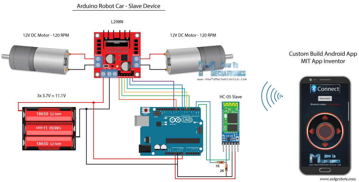
Aan de andere kant zullen we met behulp van de MIT App Inventor online applicatie onze eigen Android-app bouwen, en zo ziet het eruit.
Dus eigenlijk simuleert de app een joystick, waarvan het uiterlijk bestaat uit twee afbeeldingen, of afbeeldingssprites.
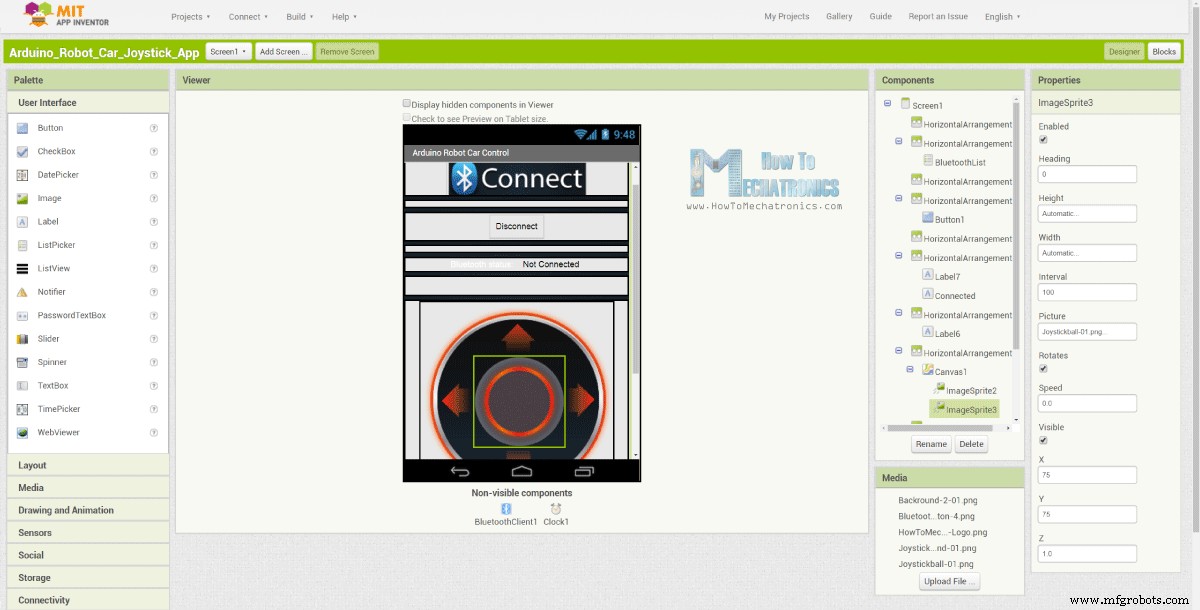
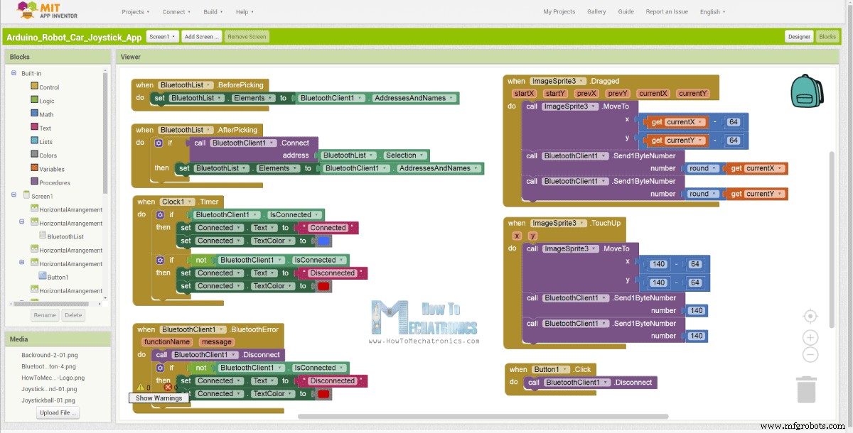
Als we naar de blokken van deze app kijken, kunnen we zien dat wanneer de joystick-sprite wordt gesleept, het beeld van de joystickbal wordt verplaatst naar de huidige locatie van onze vinger en tegelijkertijd sturen we de X en Y waarden via Bluetooth naar de Arduino-auto.
Deze waarden worden door de Arduino geaccepteerd op dezelfde manier als in het vorige voorbeeld, met behulp van de functie Serial.read.
// Read the incoming data from the Smartphone Android App
  while (Serial.available() >= 2) {
    x = Serial.read();
    delay(10);
    y = Serial.read();
  }Code language: Arduino (arduino)
Wat we hier extra moeten doen, is om de ontvangen X- en Y-waarden van de smartphone om te zetten in het bereik van 0 tot 1023, geschikt voor de onderstaande motorbesturingscode. Deze waarden zijn afhankelijk van de canvasgrootte en de X- en Y-waarden die ik van mijn app kreeg, waren van 60 tot 220, die ik met de functie map() gemakkelijk kon converteren.
// Makes sure we receive corrent values
  if (x > 60 & x < 220) {
    xAxis = map(x, 220, 60, 1023, 0); // Convert the smartphone X and Y values to 0 - 1023 range, suitable motor for the motor control code below
  }
  if (y > 60 & y < 220) {
    yAxis = map(y, 220, 60, 0, 1023);
  }Code language: Arduino (arduino)
Bij de applicatieblokken kunnen we ook zien dat wanneer de afbeeldingssprite wordt aangeraakt, de joystickbal teruggaat naar het midden van het canvas en de juiste waarden naar de auto worden gestuurd om te stoppen met bewegen. U kunt deze app vinden en downloaden op het websiteartikel, evenals de twee afbeeldingen van de joystick, zodat u uw eigen app kunt bouwen of deze app kunt aanpassen.
U kunt de Android-app hieronder downloaden, evenals de twee afbeeldingen voor de joystick:

Arduino_Robot_Car_Joystick_App.apk
1 bestand(en) 1,62 MB downloaden Arduino_Robot_Car_Joystick_App_aia_file
1 bestand(en) 171,20 KB downloaden Afbeeldingen joystick-app
1 bestand(en) 44,36 KB downloadenVolledige Arduino-code:
/*
   Arduino Robot Car Wireless Control using the HC-05 Bluetooth and custom-build Android app

             == SLAVE DEVICE - Arduino robot car ==

   by Dejan Nedelkovski, www.HowToMechatronics.com
*/

#define enA 9
#define in1 4
#define in2 5
#define enB 10
#define in3 6
#define in4 7

int xAxis, yAxis;
int  x = 0;
int  y = 0;

int motorSpeedA = 0;
int motorSpeedB = 0;

void setup() {
  pinMode(enA, OUTPUT);
  pinMode(enB, OUTPUT);
  pinMode(in1, OUTPUT);
  pinMode(in2, OUTPUT);
  pinMode(in3, OUTPUT);
  pinMode(in4, OUTPUT);

  Serial.begin(38400); // Default communication rate of the Bluetooth module
}

void loop() {
  // Default value - no movement when the Joystick stays in the center
  xAxis = 510;
  yAxis = 510;

  // Read the incoming data from the Smartphone Android App
  while (Serial.available() >= 2) {
    x = Serial.read();
    delay(10);
    y = Serial.read();
  }
  delay(10);

  // Makes sure we receive corrent values
  if (x > 60 & x < 220) {
    xAxis = map(x, 220, 60, 1023, 0); // Convert the smartphone X and Y values to 0 - 1023 range, suitable motor for the motor control code below
  }
  if (y > 60 & y < 220) {
    yAxis = map(y, 220, 60, 0, 1023);
  }

  // Y-axis used for forward and backward control
  if (yAxis < 470) {
    // Set Motor A backward
    digitalWrite(in1, HIGH);
    digitalWrite(in2, LOW);
    // Set Motor B backward
    digitalWrite(in3, HIGH);
    digitalWrite(in4, LOW);
    // Convert the declining Y-axis readings for going backward from 470 to 0 into 0 to 255 value for the PWM signal for increasing the motor speed
    motorSpeedA = map(yAxis, 470, 0, 0, 255);
    motorSpeedB = map(yAxis, 470, 0, 0, 255);
  }
  else if (yAxis > 550) {
    // Set Motor A forward
    digitalWrite(in1, LOW);
    digitalWrite(in2, HIGH);
    // Set Motor B forward
    digitalWrite(in3, LOW);
    digitalWrite(in4, HIGH);
    // Convert the increasing Y-axis readings for going forward from 550 to 1023 into 0 to 255 value for the PWM signal for increasing the motor speed
    motorSpeedA = map(yAxis, 550, 1023, 0, 255);
    motorSpeedB = map(yAxis, 550, 1023, 0, 255);
  }
  // If joystick stays in middle the motors are not moving
  else {
    motorSpeedA = 0;
    motorSpeedB = 0;
  }

  // X-axis used for left and right control
  if (xAxis < 470) {
    // Convert the declining X-axis readings from 470 to 0 into increasing 0 to 255 value
    int xMapped = map(xAxis, 470, 0, 0, 255);
    // Move to left - decrease left motor speed, increase right motor speed
    motorSpeedA = motorSpeedA - xMapped;
    motorSpeedB = motorSpeedB + xMapped;
    // Confine the range from 0 to 255
    if (motorSpeedA < 0) {
      motorSpeedA = 0;
    }
    if (motorSpeedB > 255) {
      motorSpeedB = 255;
    }
  }
  if (xAxis > 550) {
    // Convert the increasing X-axis readings from 550 to 1023 into 0 to 255 value
    int xMapped = map(xAxis, 550, 1023, 0, 255);
    // Move right - decrease right motor speed, increase left motor speed
    motorSpeedA = motorSpeedA + xMapped;
    motorSpeedB = motorSpeedB - xMapped;
    // Confine the range from 0 to 255
    if (motorSpeedA > 255) {
      motorSpeedA = 255;
    }
    if (motorSpeedB < 0) {
      motorSpeedB = 0;
    }
  }
  // Prevent buzzing at low speeds (Adjust according to your motors. My motors couldn't start moving if PWM value was below value of 70)
  if (motorSpeedA < 70) {
    motorSpeedA = 0;
  }
  if (motorSpeedB < 70) {
    motorSpeedB = 0;
  }
  analogWrite(enA, motorSpeedA); // Send PWM signal to motor A
  analogWrite(enB, motorSpeedB); // Send PWM signal to motor B
}Code language: Arduino (arduino)
Arduino Robot Car Wireless Control met NRF24L01 Transceiver Module
Nu kunnen we doorgaan naar de volgende methode, draadloze besturing van de Arduino-robotauto met behulp van de NRF24L01-transceivermodules.
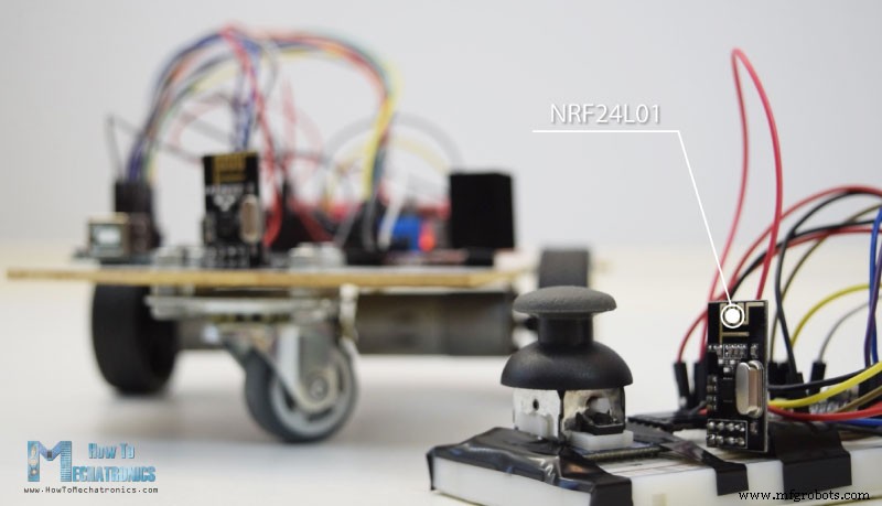
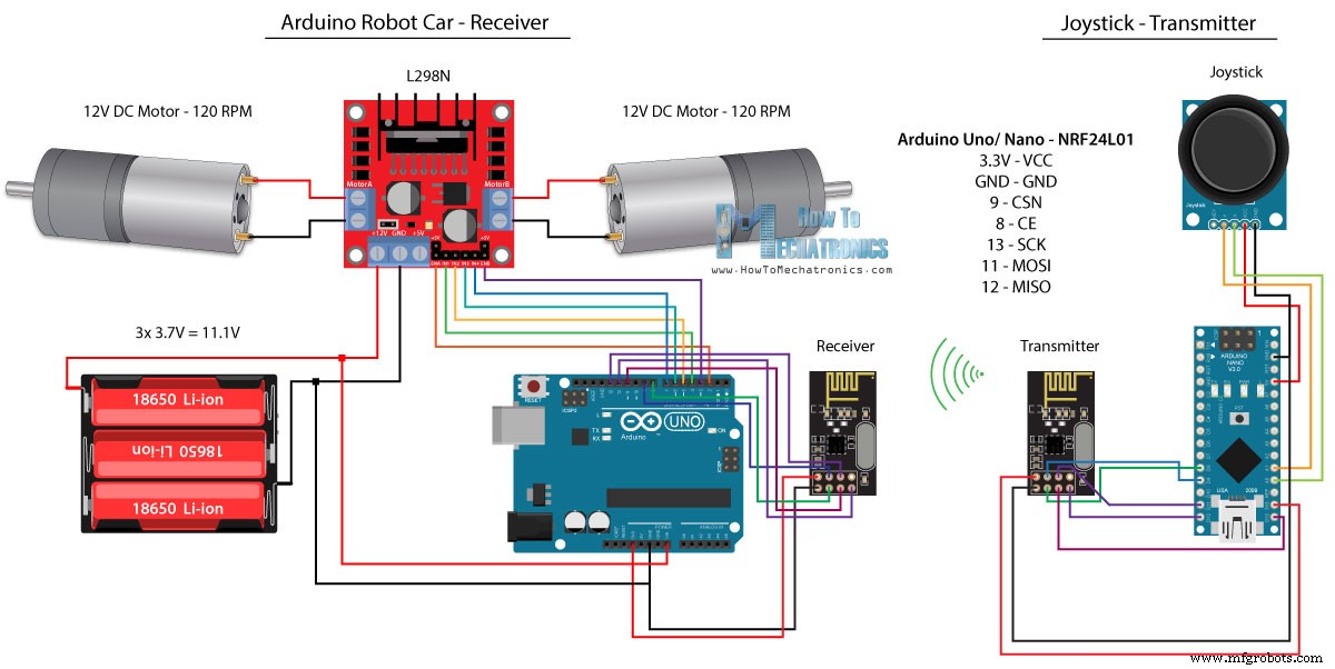
Hier is het circuitschema. We kunnen opmerken dat deze modules de SPI-communicatie gebruiken, dus in vergelijking met het vorige voorbeeld moest ik de Enable A- en Enable B-pinnen van de L298N-driver verplaatsen naar de pinnen nummer 2 en 3 van het Arduino-bord. Je kunt de NRF24L01 krijgen module op de volgende Amazon-link.
Broncode
Voor dit voorbeeld moeten we de RF24-bibliotheek installeren. Op dezelfde manier als in het vorige voorbeeld, na het definiëren van enkele pinnen en het instellen van de module als zender, lezen we de X- en Y-waarden van de joystick en sturen deze naar de andere NRF24L01-module bij de Arduino-robotauto.
Ten eerste kunnen we opmerken dat analoge uitlezingen Strings zijn, die met de functie string.toCharArray() in een tekenreeks worden geplaatst. Dan gebruiken we de radio.write() functie om die karakter array data naar de andere module te sturen.
Zendercode:
/*
   Arduino Robot Car Wireless Control using the NRF24L01 Transceiver module

             == Transmitter - Joystick ==

   by Dejan Nedelkovski, www.HowToMechatronics.com

   Library: TMRh20/RF24, https://github.com/tmrh20/RF24/
*/

#include <SPI.h>
#include <nRF24L01.h>
#include <RF24.h>

RF24 radio(8, 9); // CE, CSN
const byte address[6] = "00001";

char xyData[32] = "";
String xAxis, yAxis;

void setup() {
  Serial.begin(9600);
  radio.begin();
  radio.openWritingPipe(address);
  radio.setPALevel(RF24_PA_MIN);
  radio.stopListening();
}

void loop() {

  xAxis = analogRead(A0); // Read Joysticks X-axis
  yAxis = analogRead(A1); // Read Joysticks Y-axis
  // X value
  xAxis.toCharArray(xyData, 5); // Put the String (X Value) into a character array
  radio.write(&xyData, sizeof(xyData)); // Send the array data (X value) to the other NRF24L01 modile
  // Y value
  yAxis.toCharArray(xyData, 5);
  radio.write(&xyData, sizeof(xyData));
  delay(20);
}Code language: Arduino (arduino)
Aan de andere kant. bij de Arduino-robotauto accepteren we, na het definiëren van de module als ontvanger, gegevens met behulp van de radio.read()-functie. Vervolgens zetten we met de functie atoi() de ontvangen gegevens, of de X- en Y-waarden van de joystick, om in gehele waarden, die geschikt zijn voor de onderstaande motorbesturingscode.
// Code from the Arduino Robot Car - NRF24L01 example

if (radio.available()) {   // If the NRF240L01 module received data
    radio.read(&receivedData, sizeof(receivedData)); // Read the data and put it into character array
    xAxis = atoi(&receivedData[0]); // Convert the data from the character array (received X value) into integer
    delay(10);
    radio.read(&receivedData, sizeof(receivedData));
    yAxis = atoi(&receivedData[0]);
    delay(10);
  }Code language: Arduino (arduino)
Het is zo simpel, maar natuurlijk, zoals ik al zei, als je meer details nodig hebt over het aansluiten en instellen van de modules, kun je altijd mijn specifieke tutorial ervoor raadplegen.
Ontvangercode:
/*
   Arduino Robot Car Wireless Control using the NRF24L01 Transceiver module

             == Receiver - Arduino robot car ==

   by Dejan Nedelkovski, www.HowToMechatronics.com

   Library: TMRh20/RF24, https://github.com/tmrh20/RF24/
*/
#include <SPI.h>
#include <nRF24L01.h>
#include <RF24.h>

#define enA 2   // Note: Pin 9 in previous video ( pin 10 is used for the SPI communication of the NRF24L01)
#define in1 4
#define in2 5
#define enB 3   // Note:  Pin 10 in previous video
#define in3 6
#define in4 7

RF24 radio(8, 9); // CE, CSN
const byte address[6] = "00001";

char receivedData[32] = "";
int  xAxis, yAxis;

int motorSpeedA = 0;
int motorSpeedB = 0;

void setup() {
  pinMode(enA, OUTPUT);
  pinMode(enB, OUTPUT);
  pinMode(in1, OUTPUT);
  pinMode(in2, OUTPUT);
  pinMode(in3, OUTPUT);
  pinMode(in4, OUTPUT);
  Serial.begin(9600);
  radio.begin();
  radio.openReadingPipe(0, address);
  radio.setPALevel(RF24_PA_MIN);
  radio.startListening();
}

void loop() {

  if (radio.available()) {   // If the NRF240L01 module received data
    radio.read(&receivedData, sizeof(receivedData)); // Read the data and put it into character array
    xAxis = atoi(&receivedData[0]); // Convert the data from the character array (received X value) into integer
    delay(10);
    radio.read(&receivedData, sizeof(receivedData));
    yAxis = atoi(&receivedData[0]);
    delay(10);
  }

  // Y-axis used for forward and backward control
  if (yAxis < 470) {
    // Set Motor A backward
    digitalWrite(in1, HIGH);
    digitalWrite(in2, LOW);
    // Set Motor B backward
    digitalWrite(in3, HIGH);
    digitalWrite(in4, LOW);
    // Convert the declining Y-axis readings for going backward from 470 to 0 into 0 to 255 value for the PWM signal for increasing the motor speed
    motorSpeedA = map(yAxis, 470, 0, 0, 255);
    motorSpeedB = map(yAxis, 470, 0, 0, 255);
  }
  else if (yAxis > 550) {
    // Set Motor A forward
    digitalWrite(in1, LOW);
    digitalWrite(in2, HIGH);
    // Set Motor B forward
    digitalWrite(in3, LOW);
    digitalWrite(in4, HIGH);
    // Convert the increasing Y-axis readings for going forward from 550 to 1023 into 0 to 255 value for the PWM signal for increasing the motor speed
    motorSpeedA = map(yAxis, 550, 1023, 0, 255);
    motorSpeedB = map(yAxis, 550, 1023, 0, 255);
  }
  // If joystick stays in middle the motors are not moving
  else {
    motorSpeedA = 0;
    motorSpeedB = 0;
  }

  // X-axis used for left and right control
  if (xAxis < 470) {
    // Convert the declining X-axis readings from 470 to 0 into increasing 0 to 255 value
    int xMapped = map(xAxis, 470, 0, 0, 255);
    // Move to left - decrease left motor speed, increase right motor speed
    motorSpeedA = motorSpeedA - xMapped;
    motorSpeedB = motorSpeedB + xMapped;
    // Confine the range from 0 to 255
    if (motorSpeedA < 0) {
      motorSpeedA = 0;
    }
    if (motorSpeedB > 255) {
      motorSpeedB = 255;
    }
  }
  if (xAxis > 550) {
    // Convert the increasing X-axis readings from 550 to 1023 into 0 to 255 value
    int xMapped = map(xAxis, 550, 1023, 0, 255);
    // Move right - decrease right motor speed, increase left motor speed
    motorSpeedA = motorSpeedA + xMapped;
    motorSpeedB = motorSpeedB - xMapped;
    // Confine the range from 0 to 255
    if (motorSpeedA > 255) {
      motorSpeedA = 255;
    }
    if (motorSpeedB < 0) {
      motorSpeedB = 0;
    }
  }
  // Prevent buzzing at low speeds (Adjust according to your motors. My motors couldn't start moving if PWM value was below value of 70)
  if (motorSpeedA < 70) {
    motorSpeedA = 0;
  }
  if (motorSpeedB < 70) {
    motorSpeedB = 0;
  }
  analogWrite(enA, motorSpeedA); // Send PWM signal to motor A
  analogWrite(enB, motorSpeedB); // Send PWM signal to motor B
}Code language: Arduino (arduino)
Arduino Robot Car Wireless Control met HC-12 Long Range Transceiver
Voor de laatste methode van draadloze besturing van de Arduino-robotauto zullen we de HC-12-transceivermodules met groot bereik gebruiken. Deze modules kunnen met elkaar communiceren met afstanden tot 1,8 km.
Het schakelschema voor dit voorbeeld is bijna hetzelfde als dat voor de HC-05 Bluetooth-modules, omdat ze dezelfde methode gebruiken voor communicatie met de Arduino, via de seriële poort.
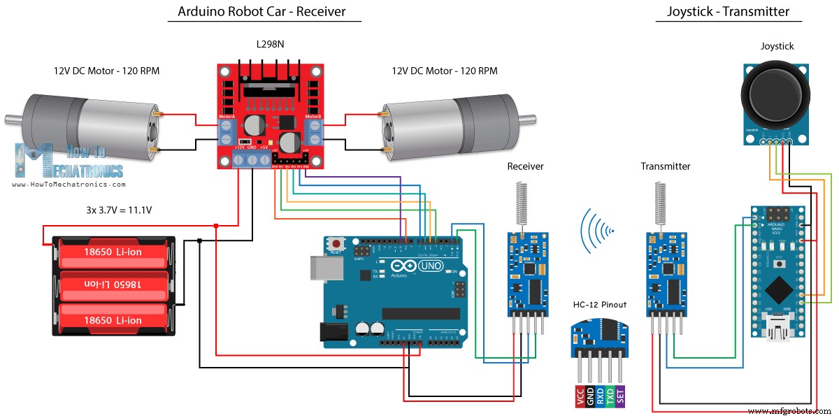
Je kunt de HC-12 Transceiver-module krijgen via de volgende Amazon-link.
Broncode
De Joystick-code is precies dezelfde als die voor de Bluetooth-communicatie. We lezen gewoon de analoge waarden van de joystick en sturen ze naar de andere module met behulp van de functie Serial.write() .
Zendercode:
/*
   Arduino Robot Car Wireless Control using the HC-12 long range wireless module

                == Transmitter - Joystick ==

   by Dejan Nedelkovski, www.HowToMechatronics.com
*/

int xAxis, yAxis;

void setup() {
  Serial.begin(9600); // Default communication rate of the Bluetooth module
}

void loop() {
  xAxis = analogRead(A0); // Read Joysticks X-axis
  yAxis = analogRead(A1); // Read Joysticks Y-axis

  // Send the values via the serial port to the slave HC-05 Bluetooth device
  Serial.write(xAxis/4); // Dividing by 4 for converting from 0 - 1023 to 0 - 256, (1 byte) range
  Serial.write(yAxis/4);
  delay(20);
}Code language: Arduino (arduino)
Aan de andere kant, met de while()-lus, wachten we tot de gegevens aankomen, lezen deze dan met de functie Serial.read() en zetten deze terug in het bereik van 0 tot 1023, geschikt voor de onderstaande motorbesturingscode.
Ontvangercode:
/*
   Arduino Robot Car Wireless Control using the HC-12 long range wireless module

             == Receiver - Arduino robot car ==

   by Dejan Nedelkovski, www.HowToMechatronics.com
*/

#define enA 9
#define in1 4
#define in2 5
#define enB 10
#define in3 6
#define in4 7

int xAxis, yAxis;
int  x = 0;
int  y = 0;

int motorSpeedA = 0;
int motorSpeedB = 0;

void setup() {
  pinMode(enA, OUTPUT);
  pinMode(enB, OUTPUT);
  pinMode(in1, OUTPUT);
  pinMode(in2, OUTPUT);
  pinMode(in3, OUTPUT);
  pinMode(in4, OUTPUT);

  Serial.begin(9600); // Default communication rate of the Bluetooth module
}

void loop() {
  // Default value - no movement when the Joystick stays in the center
  xAxis = 510;
  yAxis = 510;

  // Read the incoming data from the
  while (Serial.available() == 0) {}
  x = Serial.read();
  delay(10);
  y = Serial.read();
  delay(10);

  // Convert back the 0 - 255 range to 0 - 1023, suitable for motor control code below
  xAxis = x * 4;
  yAxis = y * 4;

  // Y-axis used for forward and backward control
  if (yAxis < 470) {
    // Set Motor A backward
    digitalWrite(in1, HIGH);
    digitalWrite(in2, LOW);
    // Set Motor B backward
    digitalWrite(in3, HIGH);
    digitalWrite(in4, LOW);
    // Convert the declining Y-axis readings for going backward from 470 to 0 into 0 to 255 value for the PWM signal for increasing the motor speed
    motorSpeedA = map(yAxis, 470, 0, 0, 255);
    motorSpeedB = map(yAxis, 470, 0, 0, 255);
  }
  else if (yAxis > 550) {
    // Set Motor A forward
    digitalWrite(in1, LOW);
    digitalWrite(in2, HIGH);
    // Set Motor B forward
    digitalWrite(in3, LOW);
    digitalWrite(in4, HIGH);
    // Convert the increasing Y-axis readings for going forward from 550 to 1023 into 0 to 255 value for the PWM signal for increasing the motor speed
    motorSpeedA = map(yAxis, 550, 1023, 0, 255);
    motorSpeedB = map(yAxis, 550, 1023, 0, 255);
  }
  // If joystick stays in middle the motors are not moving
  else {
    motorSpeedA = 0;
    motorSpeedB = 0;
  }

  // X-axis used for left and right control
  if (xAxis < 470) {
    // Convert the declining X-axis readings from 470 to 0 into increasing 0 to 255 value
    int xMapped = map(xAxis, 470, 0, 0, 255);
    // Move to left - decrease left motor speed, increase right motor speed
    motorSpeedA = motorSpeedA - xMapped;
    motorSpeedB = motorSpeedB + xMapped;
    // Confine the range from 0 to 255
    if (motorSpeedA < 0) {
      motorSpeedA = 0;
    }
    if (motorSpeedB > 255) {
      motorSpeedB = 255;
    }
  }
  if (xAxis > 550) {
    // Convert the increasing X-axis readings from 550 to 1023 into 0 to 255 value
    int xMapped = map(xAxis, 550, 1023, 0, 255);
    // Move right - decrease right motor speed, increase left motor speed
    motorSpeedA = motorSpeedA + xMapped;
    motorSpeedB = motorSpeedB - xMapped;
    // Confine the range from 0 to 255
    if (motorSpeedA > 255) {
      motorSpeedA = 255;
    }
    if (motorSpeedB < 0) {
      motorSpeedB = 0;
    }
  }
  // Prevent buzzing at low speeds (Adjust according to your motors. My motors couldn't start moving if PWM value was below value of 70)
  if (motorSpeedA < 70) {
    motorSpeedA = 0;
  }
  if (motorSpeedB < 70) {
    motorSpeedB = 0;
  }
  analogWrite(enA, motorSpeedA); // Send PWM signal to motor A
  analogWrite(enB, motorSpeedB); // Send PWM signal to motor B
}Code language: Arduino (arduino)
Dus dat is zo ongeveer alles voor deze tutorial. Stel gerust een vraag in de opmerkingen hieronder.
Productieproces
- Raspberry Pi-robot bestuurd via Bluetooth
- Universele afstandsbediening met Arduino, 1Sheeld en Android
- DIY voltmeter met Arduino en smartphone
- Arduino met Bluetooth om een LED te bedienen!
- Bedien Arduino Rover met Firmata en Xbox One Controller
- Autoteller met Arduino + Processing + PHP
- Volledige controle over uw tv met Alexa en Arduino IoT Cloud
- FM-radio met Arduino en RDA8057M
- BLUE_P:Wireless Arduino Programming Shield
- Autobesturing met Arduino Uno en Bluetooth
- Geweldige besturingscomputer met handbeweging en Arduino