


Alzheimer Assistent
Componenten en benodigdheden
 |
| × | 1 | |||
 |
| × | 1 | |||
| × | 1 | ||||
 |
| × | 1 | |||
 |
| × | 1 | |||
 |
| × | 1 | |||
 |
| × | 1 | |||
| × | 1 | ||||
| × | 1 | ||||
| × | 1 |
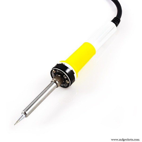
Benodigde gereedschappen en machines
 |
|
Apps en online services
 |
| |||
 |
| |||
 |
|
Over dit project
Deze feiten die rechtstreeks van de website van de Alzheimer's Association zijn geciteerd (overgenomen in september 2017) zijn voldoende om iemand een idee te geven van de problemen die een persoon moet doormaken als zij of hun dierbaren de ziekte van Alzheimer hebben.
Als maker heb ik hier over nagedacht en besloten dat ik een draagbaar apparaat ga bouwen, een systeem dat zowel patiënten als hun verzorgers kan helpen.
Dit systeem moet minimaal de volgende taken kunnen uitvoeren:
- De patiënt herinneren aan het uitvoeren van taken die hij/zij dagelijks moet doen (zoals medicijnen, lichaamsbeweging, enz.)
- Bewaak waar de patiënt zich in huis bevindt
- Waarschuw de verzorgers in geval van een noodsituatie
- Geef de tijd weer (het is tenslotte een horloge!)
- Het moet draagbaar en gebruiksvriendelijk zijn, zelfs voor een oudere patiënt
- De kosten moeten tot een minimum worden beperkt
Toen ik Infineon's Sensor Hub Nano zag, leek het een goede kandidaat in een dergelijk project, vanwege zijn zeer kleine formaat en BLE-mogelijkheden. Met de nauwkeurige drukmeting kan het worden gebruikt om te detecteren of de patiënt is gevallen en ook om te vertellen waar de patiënt zich precies in huis bevindt.
Ik zal de volgende onderdelen gebruiken voor het bare-bones-project om te functioneren:
- Infineon's Sensor Hub Nano
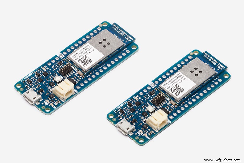
- Arduino MKR1000
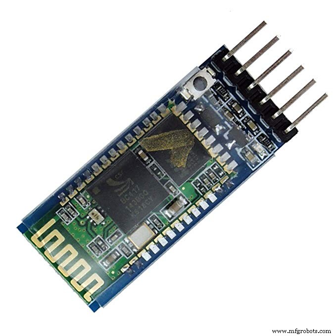
- HC-05 Bluetooth-module
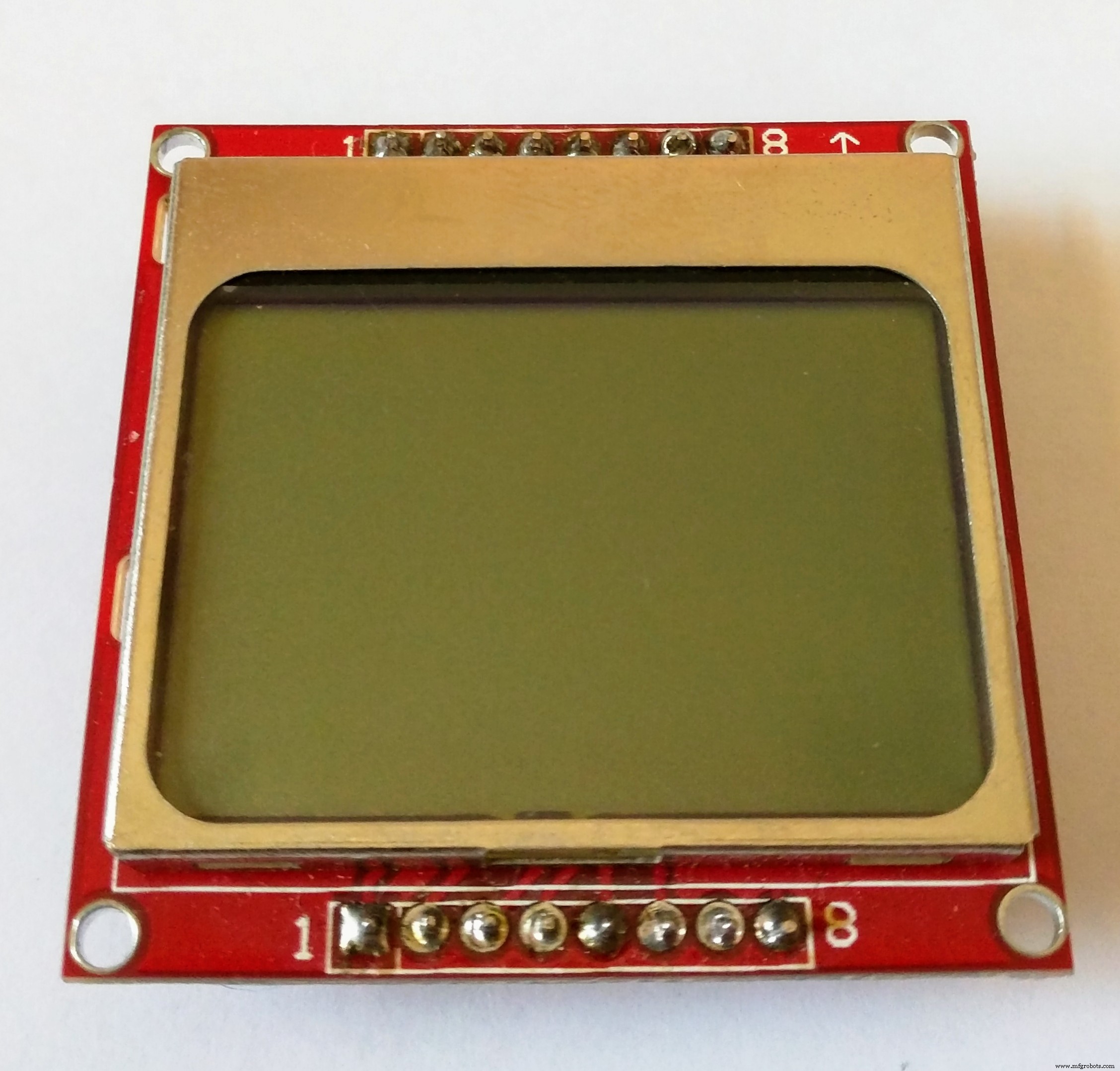
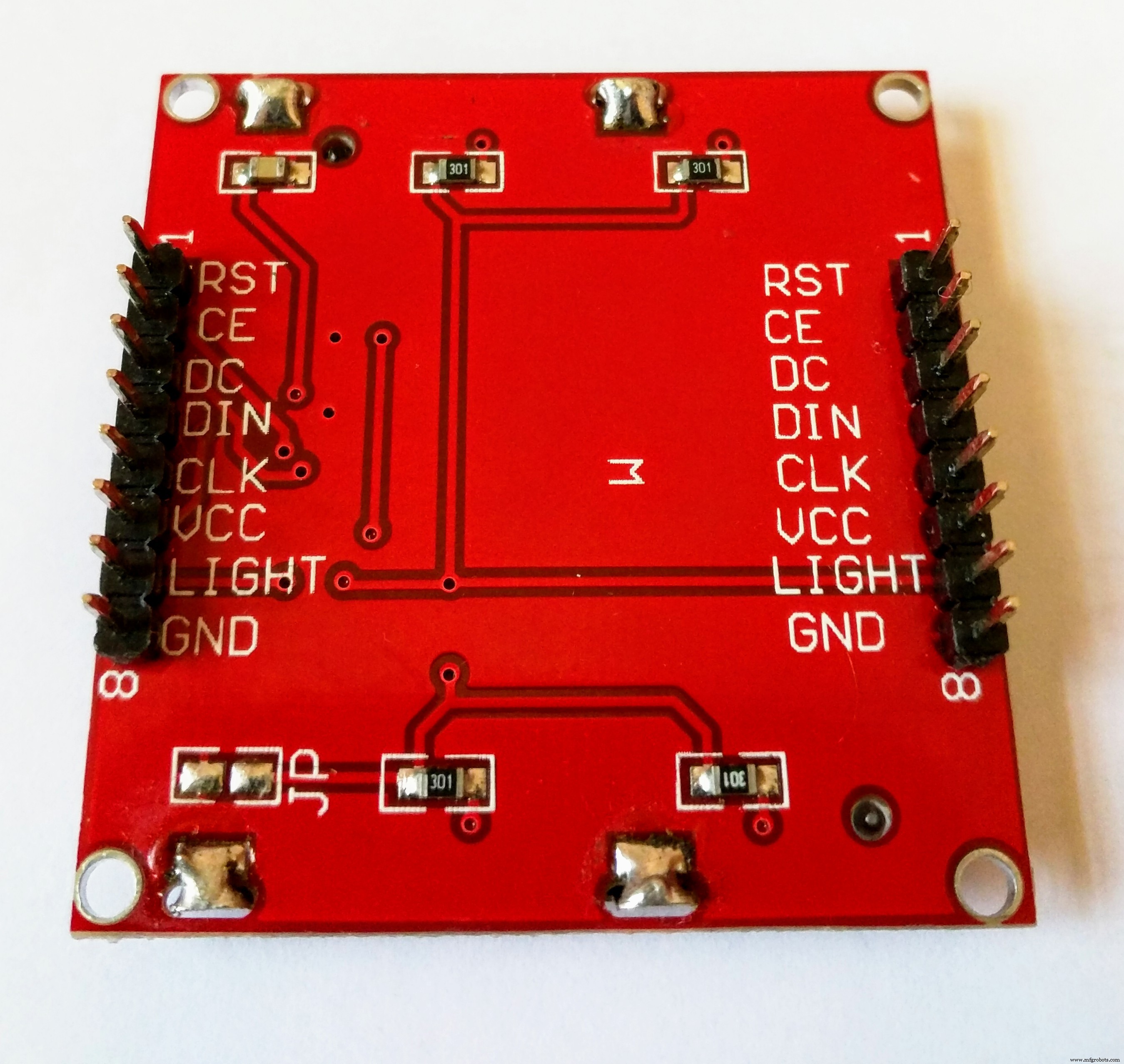
- Nokia 5110-scherm

U zult begrijpen wat ik bedoel met "kaal project" als u het gedeelte 'Alzheimerassistent personaliseren' leest.
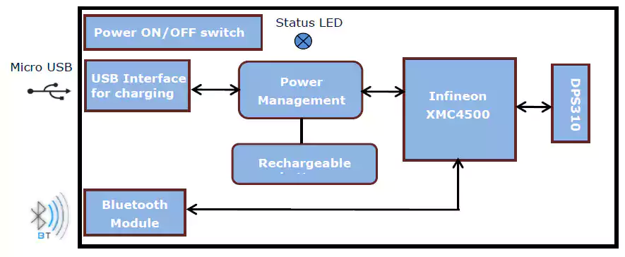
Hoe het werkt
In dit gedeelte zal ik kort beschrijven hoe het horloge werkt en de stappen schetsen die we moeten doorlopen om het te laten werken.
Het Sensor Hub Nano-evaluatiebord van Infineon heeft een DPS310-luchtdruksensor, die zijn gegevens via bluetooth door het evaluatiebord stuurt. De druk-, hoogte- en temperatuurwaarden kunnen worden bekeken in de Android-app van Infineon (download hier) en in SES2G-evaluatiesoftware. Gebruikers kunnen ook applicaties voor Android bouwen met de bibliotheek die Infineon biedt, op basis van hun eigen behoefte.
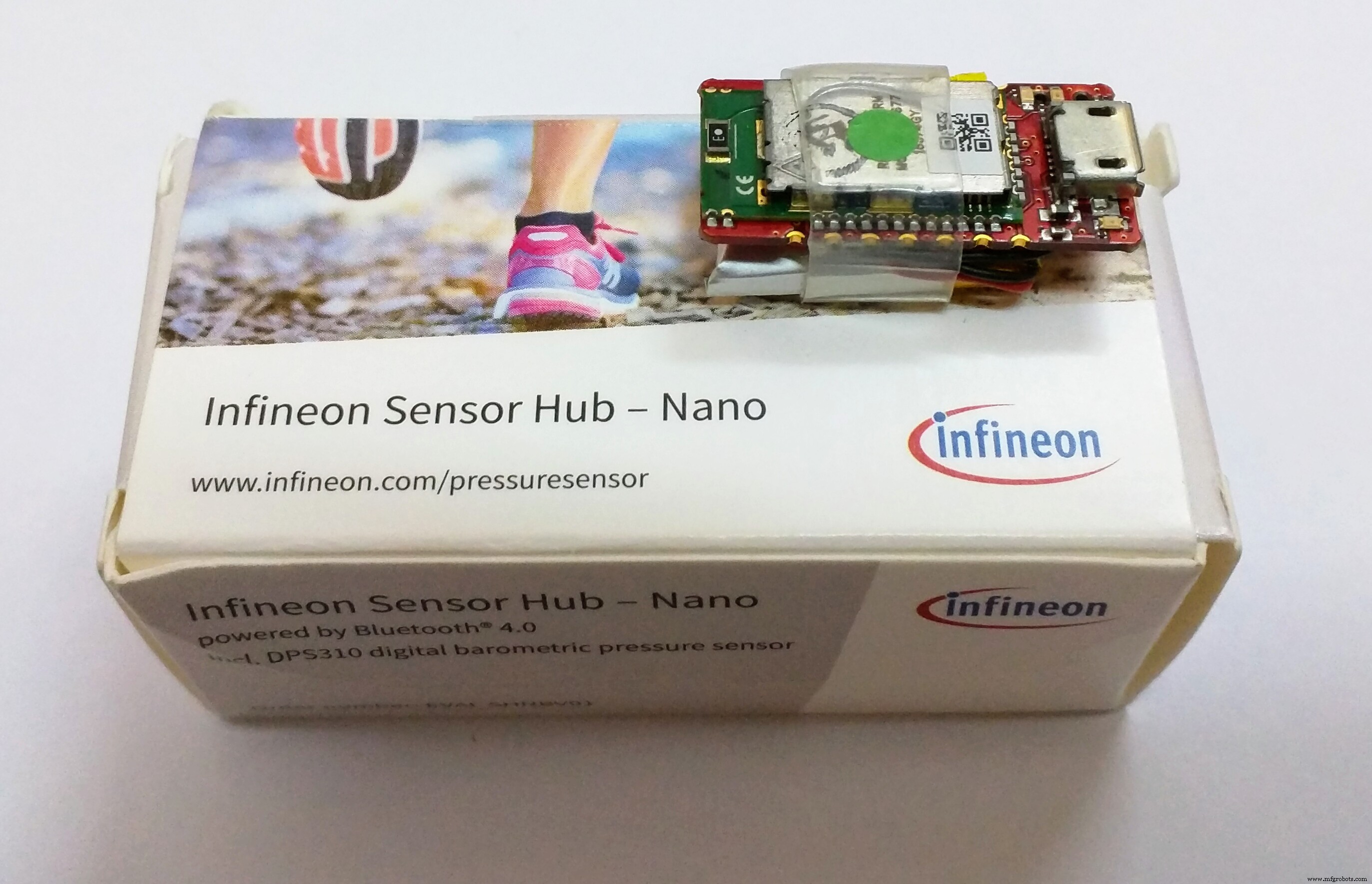
Meer informatie over de Sensor Hub Nano vind je hier.
Maar ik wil dat de Alzheimer-assistent werkt zonder een Android-telefoon ertussen. Het moet een wearable zijn die op zichzelf kan werken, maar ook de mogelijkheid heeft om verbinding te maken met een smartphone om de sensorgegevens te bekijken. Dus besloot ik dat ik een Arduino MKR1000-bord zou gebruiken vanwege zijn kleine vormfactor en wifi-mogelijkheden, en het op de een of andere manier zou verbinden met de Sensor Hub Nano.
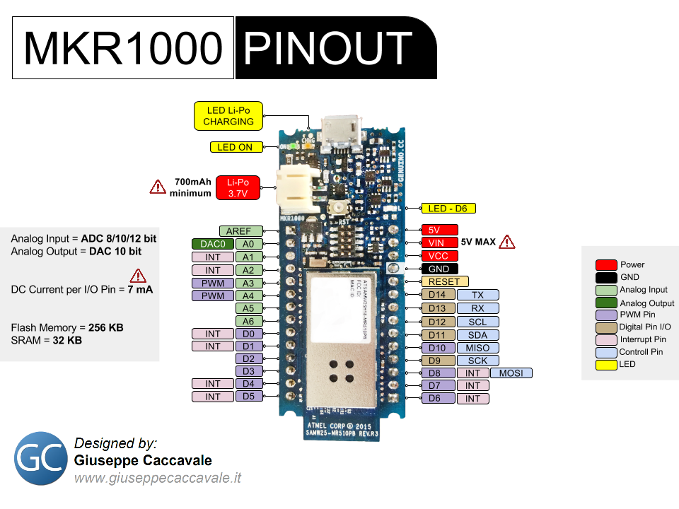
Dit is de pinout voor de Arduino MKR1000 die u handig zult vinden:
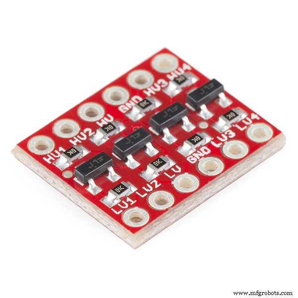
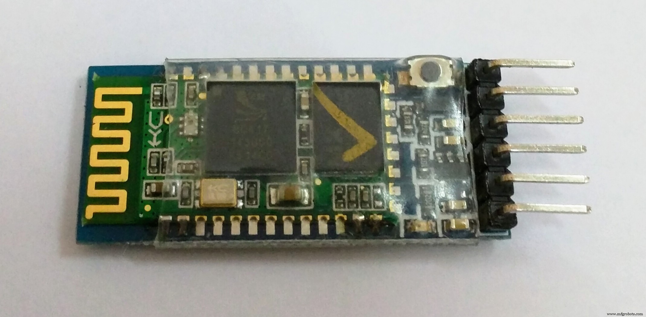
Ik had een HC-05 bluetooth module, en die moest ik dus gebruiken voor de verbinding tussen de Arduino MKR1000 en de Sensor Hub Nano. Maar eerst moeten we de HC-05 goed aansluiten op de hardware Tx- en Rx-pinnen van de Arduino, rekening houdend met de logische niveaus. Mijn bluetooth-module werkt op de 3.3v, wat hetzelfde is als de MKR1000, dus er was geen spanningsniveauverschuiver nodig. Maar als je bluetooth-module werkt op het 5v-niveau, moet je mogelijk een niveauverschuiver gebruiken die lijkt op de getoonde.
Na het afstemmen van de spanningsniveaus, moeten we de HC-05 koppelen met de Sensor Hub Nano om de datacommunicatie tussen hen te starten, en een gemakkelijke manier vinden om ze automatisch te laten koppelen telkens wanneer de Sensor Hub Nano in het bluetooth-bereik van de HC komt -05.
Om dat te doen, dacht ik eraan om de HC-05 te configureren om te fungeren als een bluetooth 'master'-apparaat, en het alleen te koppelen met een specifiek MAC-adres; die van de Sensor Hub Nano. Dus nadat je het zo hebt geconfigureerd, zoekt het, zodra je de HC-05 inschakelt, naar een apparaat met een specifiek MAC-adres (dat van de Sensor Hub Nano), en koppelt het er automatisch aan, en laat het aan de gebruiker over om te verzenden en gegevens ontvangen.
Dit wordt gedaan met behulp van AT-modusopdrachten voor de HC-05 en wordt behandeld in het gedeelte "De Bluetooth-module configureren".
Opmerking:ik heb een document bijgevoegd dat ik online heb gevonden, waarin alle AT-commando's staan vermeld die de HC-05 ondersteunt, dus gebruik ze indien nodig.
Als het eenmaal is gekoppeld en correct is aangesloten, is het verzenden van opdrachten naar de Sensor Hub Nano als een Bluetooth-terminal. Je kunt de commando's die ik hierboven heb gespecificeerd gebruiken door ze eenvoudig af te drukken als een string, via de hardware seriële poort waarop de HC-05 is aangesloten. Dit is bijvoorbeeld de opdracht die u verzendt om de stroom sensorgegevens te starten:
$start_sensor id=1 //Om de stroom van sensorgegevens te starten Hier is een lijst van de commando's die ik ken:
$hello id=//Hallo
$info id=//Info
$sinfo id=1 //Sensorinfo
$set_mode sid=1;md=mode;val=bg //Lage energie
$set_mode sid=1;md=prs_osr;val=16 //Standaardmodus
$set_mode sid=1;md=prs_mr;val=32 //Hoge precisie
$start_sensor id=1 //Start
$stop id=//Stop
De sensorgegevens afkomstig van de Sensor Hub Nano hebben de volgende indeling:
$1,t,36.9299,1154206 //Temperatuur
$1,p,997.6813.154206 //Druk
$1,a,130.4305.1154206 //Hoogte
Opmerking:ik wil graag een verwijzing geven naar Peter Smith's blogbericht, wat me hielp om de communicatie met de Sensor Hub Nano via bluetooth te starten.
Zodra we de gegevensstroom vanuit de module kunnen starten, hebben we een manier nodig om de gegevens eruit te ontleden. Dit was, moet ik toegeven, het moeilijkste deel van het project; zodra u de opdracht verzendt om de gegevensstroom te starten, verzendt de Sensor Hub Nano gewoon een gegevensstroom, en laat het aan het apparaat dat de gegevens ontvangt om er iets zinnigs van te ontleden. Dus, na het uitproberen van vele methoden van verschillende complexiteit (die ik hier niet zal bespreken), was dit de eenvoudigste en meest efficiënte methode die ik bedacht, om gegevens van de Sensor Hub Nano te ontleden.
void getSensorValues() {
 //Haalt de sensorwaarden op van de Sensor Hub Nano via de Serial1-poort
 String junkVal;
 if (Serial1.available()) {
 junkVal =Serial1.readStringUntil('\n');
 junkVal =Serial1.readStringUntil('t');
 t =Serial1.parseFloat();
 junkVal =Serial1.readStringUntil('p');
 p =Serial1.parseFloat();
 junkVal =Serial1.readStringUntil('a');
 a =Serial1.parseFloat();
 junkVal =Serial1.readStringUntil('\n');
 }
}
Er wordt ook een display op de Arduino aangesloten om met de gebruiker te communiceren en eventuele berichten weer te geven, of om de tijd of de gegevens van de sensor weer te geven (hierover meer als u verder leest).
Zodra u de gegevens in de Arduino MKR1000 hebt ontvangen, kunt u de gegevens dankzij de draadloze connectiviteit naar een aantal verschillende IoT-platforms sturen, zoals Cayenne of Blynk.

Ik had besloten om Cayenne hiervoor te gebruiken, omdat ik onder de indruk was van de prachtige interface en eenvoudige installatie. Maar helaas had het een aantal bugs met de MKR1000 WiFi-verbinding waardoor we geen pinnen konden selecteren. Ik moet zeggen dat de jongens bij Cayenne erg behulpzaam waren, maar het probleem was nog steeds niet opgelost. Daarom heb ik uiteindelijk besloten om Blynk te gebruiken, maar ze lijken erg op elkaar in gebruik, dus door een paar regels Arduino-code te wijzigen, kun je overschakelen van Blynk naar Cayenne als je het wilt testen of als het probleem eenmaal is opgelost opgelost. Beide hebben min of meer dezelfde functies, dus het is gewoon je eigen voorkeur. Maar het enige voordeel van Cayenne is dat je het ook op een pc kunt openen, terwijl Blynk alleen op smartphones werkt.
Nu hebben we gegevens ontvangen van de Sensor Hub Nano, deze in de Arduino gezet en overgebracht naar een IoT-platform (van nu af aan zal ik zeggen Blynk), en dus hoef je nu alleen nog de Alzheimer-assistent te personaliseren volgens naar uw eigen behoeften, en dat wordt behandeld in een andere sectie (val- en locatiedetectie worden daar besproken).
Opmerking:ik heb geprobeerd elke stap in detail te documenteren, maar als je iets niet weet (zoals het uploaden van code naar je Arduino), zou het een beter idee zijn om naar de Arduino te gaan startpagina , wees er een tijdje mee vertrouwd en kom er dan op terug, als je tenminste de basis kent.
De bluetooth-module configureren
Het eerste dat u moet doen, is het MAC-adres van uw Sensor Hub Nano Evaluation Kit ophalen. Er zullen veel verschillende manieren zijn om dat te doen, maar ik zal vertellen hoe ik het deed.
Koppel de Sensor Hub Nano met uw smartphone:
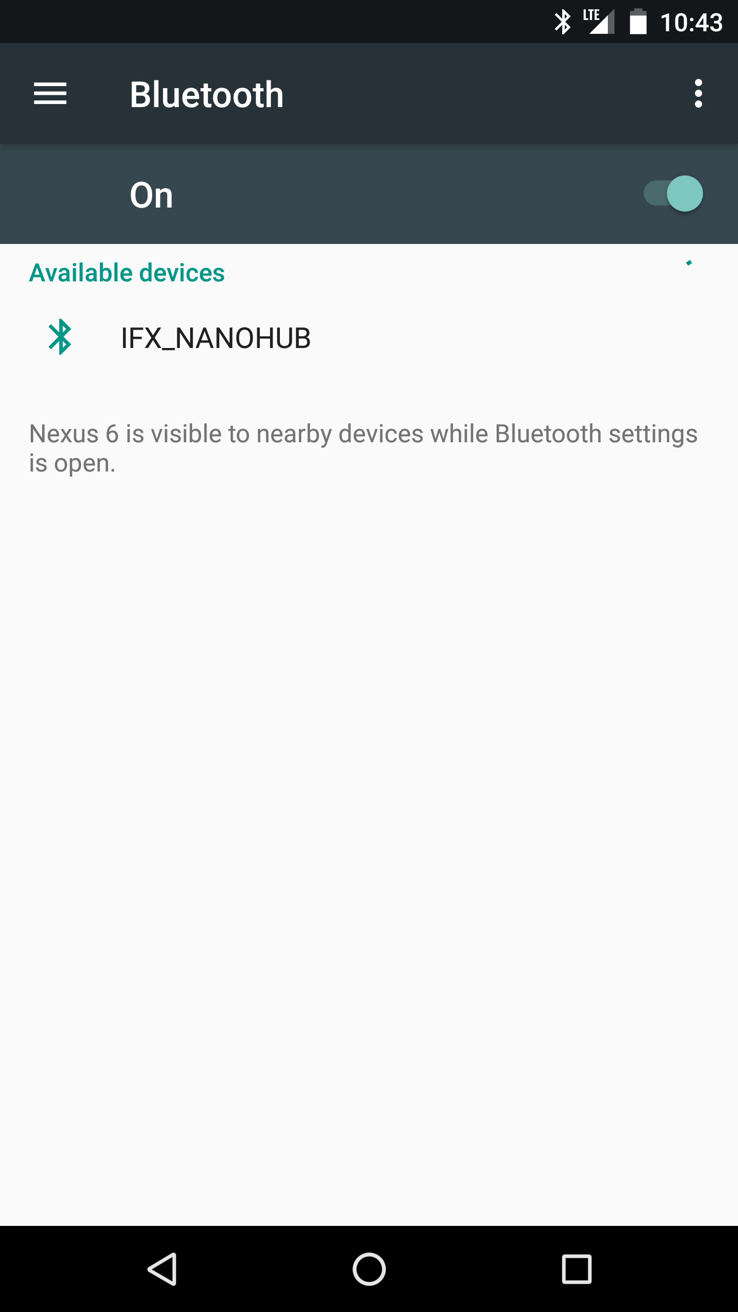

Download Infineon's Sensor Hub Nano Evaluation-app (voor Android) vanaf hier en schakel uw Sensor Hub Nano in. Open de app en de Sensor Hub Nano wordt weergegeven als "IFX_NANOHUB", met het MAC-adres eronder.
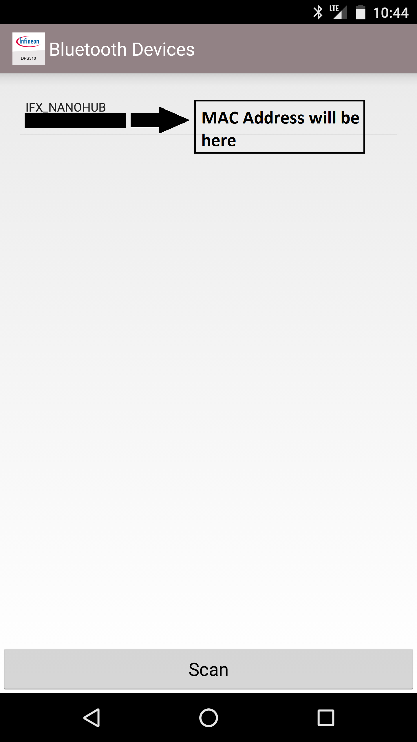
Noteer dit want je hebt het later nodig.
Opmerking:je kunt de Sensor Hub Nano beter ontkoppelen van je smartphone als je hem nu niet gebruikt, want als je telefoon in de buurt is met bluetooth aan en de Sensor Hub Nano is gekoppeld, maakt de telefoon er automatisch verbinding mee . En wanneer u de HC-05 instelt en probeert te koppelen met de Nano Hub, maakt hij gewoon geen verbinding.
De HC-05 in de AT-modus krijgen:
In de AT-modus kunnen we de instellingen van de HC-05 Bluetooth-module configureren; stel de baudrate in of stel in of u verbinding wilt maken als een slave- of masterapparaat en meer. We zullen enkele instellingen voor de module moeten wijzigen zodat deze gegevens met succes kan ophalen van Infineon's Sensor Hub Nano.
Upload eerst de schets "AT Commands" naar de Arduino MKR1000. Dit stelt ons in staat om commando's te geven aan de Bluetooth-module in AT-modus, via de Arduino MKR1000.
// Originele schets van Martyn Currey's blog hier:
// http://www.martyncurrey.com/arduino-with-hc-05-bluetooth-module-at-mode/
// />//
// Schets aangepast door mij om te werken met Arduino MKR1000!
//
// Basis Bluetooth-schets
// Sluit de HC-05-module aan en communiceer via de seriële monitor
//
// De HC-05 standaardinstellingen naar de communicatiemodus wanneer deze voor het eerst wordt ingeschakeld.
// Moet in AT-modus worden gezet
// Na een fabrieksreset is de standaard baudrate voor communicatiemodus 38400
char c =' ';
void setup() {
// start de seriële communicatie met de hostcomputer
Serial.begin(9600);
Serial.println ("Arduino met HC-05 is klaar");
// start de communicatie met de HC-05 met 38400
Serial1.begin(38400);
Serial.println("Serial1 begon bij 38400");
}
void loop() {
// Blijf lezen vanaf HC-05 en stuur naar Arduino Serial Monitor
if (Serial1.available())
{
c =Serie1.lezen();
Serial.write(c);
}
// Blijf lezen vanaf Arduino Serial Monitor en stuur naar HC-05
if (Serial.available())
{
c =Serial.read( );
// spiegel de commando's terug naar de seriële monitor
// maakt het gemakkelijk om de commando's te volgen
Serial.write(c);
Serial1.write(c);
}
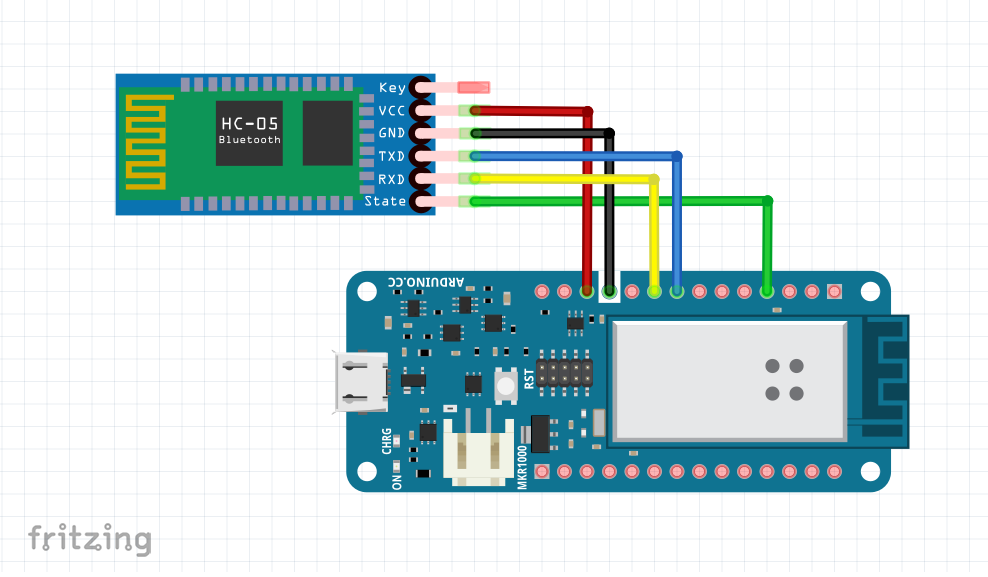
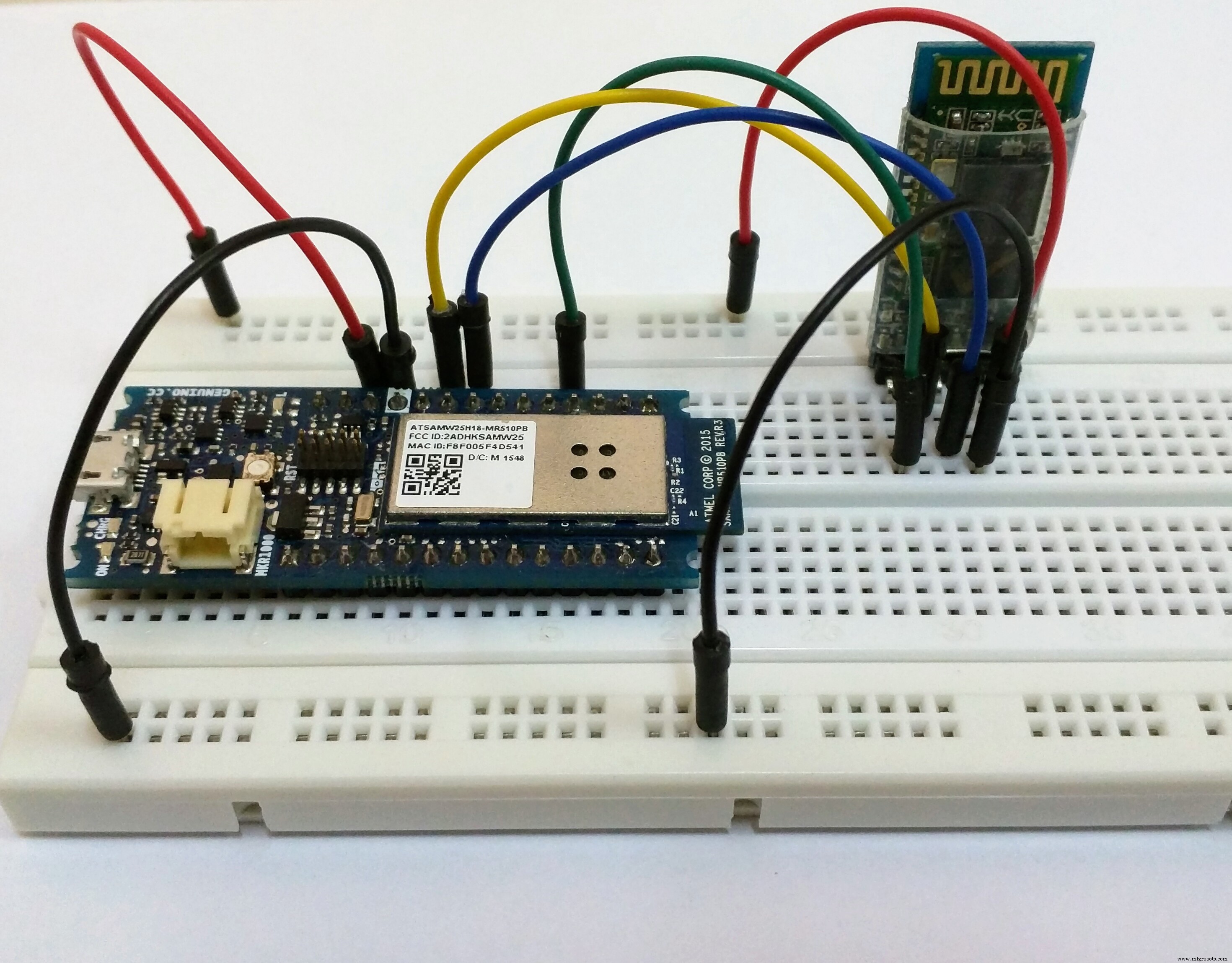
} Sluit vervolgens alleen de Bluetooth-module aan op de Arduino MKR1000 volgens het diagram.
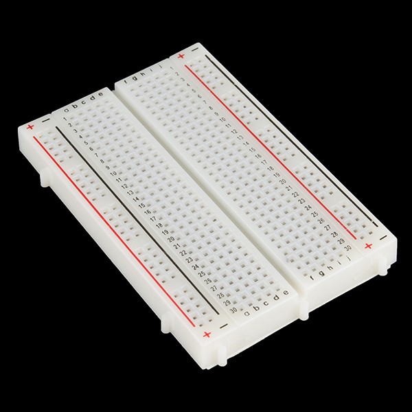
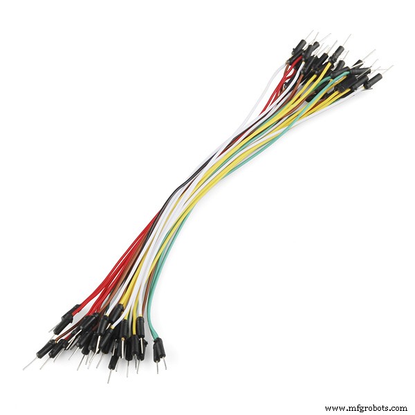
Opmerking:het zou een goed idee zijn om alles eerst op een breadboard aan te sluiten en pas over te gaan tot de juiste bedrading als je het goed hebt ingesteld.
Als je de Sensor Hub Nano en de HC-05 probeert aan te zetten, zul je zien dat ze op dit moment niet automatisch verbinding maken. Dit is wat je zou zien:
Om de HC-05-instellingen te wijzigen, moet u uw Bluetooth-module in de AT-modus zetten. De methode om dit te doen, hangt af van welk breakout-bord je hebt en daarom moet je het misschien anders doen. Als je een andere module hebt dan degene die ik heb, ga dan naar Martyn Currey's blog hier waar je gedetailleerde informatie kunt vinden over hoe je de HC-05 bluetooth-modules in AT-modus kunt krijgen. Als je vastzit, google je probleem of opmerking en ik zal proberen te helpen.
Mijn Bluetooth-module heeft de knopschakelaar, dus ik moet de volgende stappen uitvoeren om hem in de AT-opdrachtmodus te krijgen (vergeet niet om de AT-opdrachtcode naar de Arduino te uploaden):
- Ontkoppel de voeding van de module. (TX- en RX-lijnen zijn nog steeds verbonden!)
- Houd de knopschakelaar op de module gesloten ingedrukt
- Schakel de stroom in terwijl je de knop ingedrukt houdt
- Als de LED gaat branden, laat u de schakelaar los
Een video die laat zien hoe je de HC-05 in AT-modus krijgt:
Eenmaal in de AT-modus zul je een aanzienlijk verschil merken in het patroon van de LED-knipperingen op de HC-05. In de communicatiemodus knippert de LED snel, ongeveer 5 keer per seconde, terwijl in de AT-modus de LED eenmaal per paar seconden knippert.
De HC-05-module instellen:
Open de seriële monitor, stel de baudrate in op 9600 en selecteer “Both NL &CR”.
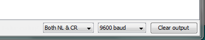
Opmerking:je moet het instellen op nieuwe regel en regelterugloop, anders werken AT-commando's niet.
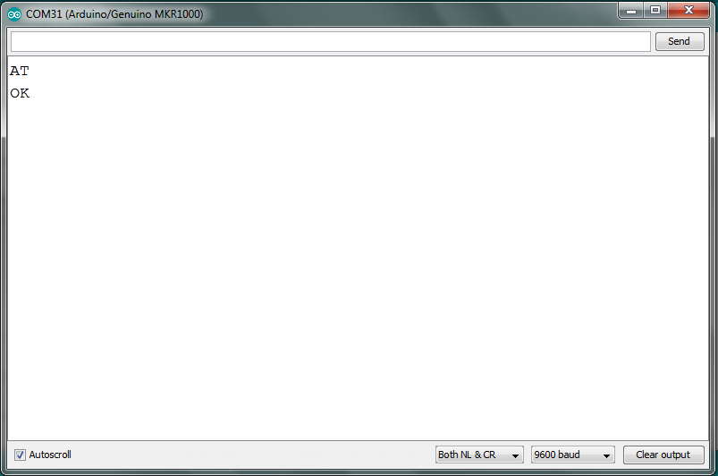
Typ "AT" in de seriële monitor en u zou een "OK" moeten ontvangen. Als je dat doet, kun je verder gaan en de commando's geven zoals ik deed.
In principe moeten we deze instellingen wijzigen in de AT-modus:
- Alle momenteel gekoppelde apparaten verwijderen
- Zorg ervoor dat het alleen verbinding maakt met een opgegeven Bluetooth MAC-adres
- Stel Bluetooth-verbindingsmodus in op 'Master'
- Geef het MAC-adres op waarmee we verbinding moeten maken
- Stel de baudrate in op 115200, stopbit op 2 bits en even pariteit
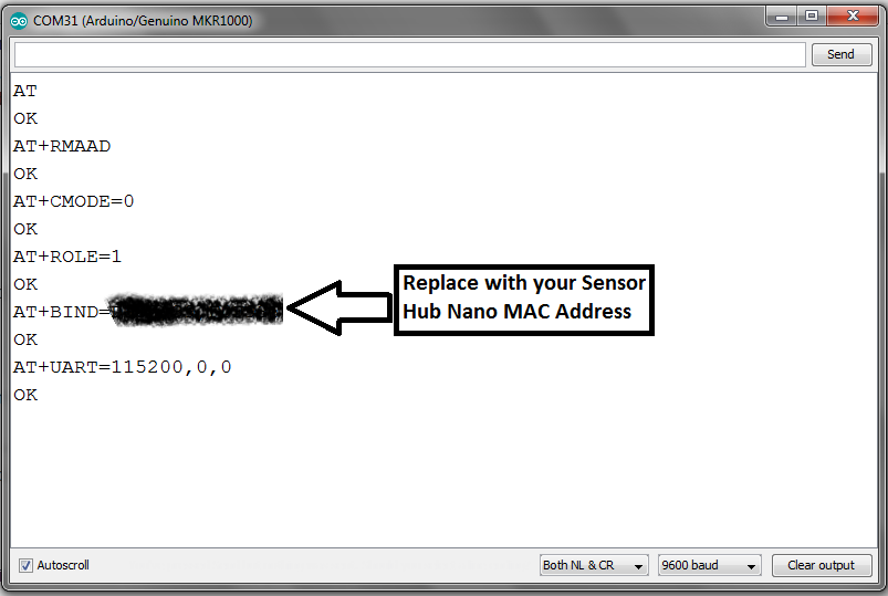
De bovenstaande instructies zijn gegeven zodat u ze kunt gebruiken, zelfs als u een andere Bluetooth-module heeft, door te verwijzen naar de opdrachten en wat ze doen. Maar nu zal ik de opdrachten opsommen die ik heb gegeven voor de HC-05 om te koppelen met de Sensor Hub Nano.
- AT+RMAAD
- AT+CMODE=0
- AT+ROLE=1
- AT+BIND=1234,56,abcdef (Vervangen door het MAC-adres van de Sensor Hub Nano)
- AT+UART=115200,0,0
Hier is een log van mijn AT-commando's ter referentie:
U moet nu de Arduino loskoppelen om de Bluetooth-module uit te schakelen. Hierdoor komt het terug in de communicatiemodus.
Opmerking:als je iets verprutst in de HC-05-instellingen, is het een goed idee om de module terug te zetten naar de standaardinstellingen en helemaal opnieuw te beginnen met het commando:AT+ORGL
De verbinding testen:
Nu moet je testen of de laatste stap succesvol was; u kunt dat doen door de Sensor Hub Nano in te schakelen. De blauwe LED zal heel langzaam knipperen, eens in de paar seconden. Sluit vervolgens uw Arduino aan op uw pc en let op de verandering in de LED-knipperingen op zowel de HC-05 als de Sesnor Hub Nano.
Kijk naar het knipperen nu en vergelijk het met het knipperen ervoor:
Er is een merkbaar verschil en je moet weten dat beide modules zijn aangesloten. U kunt nu naar het volgende deel gaan, om het project te bedraden en te testen.
Opmerking:als u uw smartphone eerder met de Sensor Hub Nano hebt gekoppeld, moet u deze mogelijk ontkoppelen, anders zou dit verbindingsproblemen veroorzaken. Het kan maar met één apparaat tegelijk verbinding maken.
Het kale project testen
Zodra u een juiste verbinding tussen de HC-05 en de Sensor Hub Nano hebt bevestigd door de knipperende LED-patronen, gaat u verder met het instellen van de Blynk-app op de smartphone.
De Blynk-app instellen:
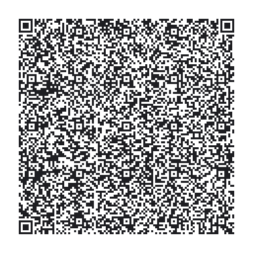
Download hier de Blynk-app (als je dat nog niet hebt gedaan) voor je iOS- of Android-apparaat en scan de QR-code via de Blynk-app. Het repliceert automatisch de basiswidgets die op dit moment nodig zijn.
U ziet een soortgelijk scherm:
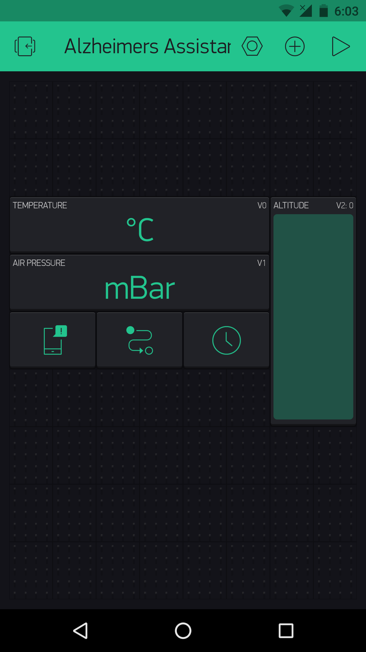
Breng hier op dit moment geen wijzigingen aan en lees gewoon verder.
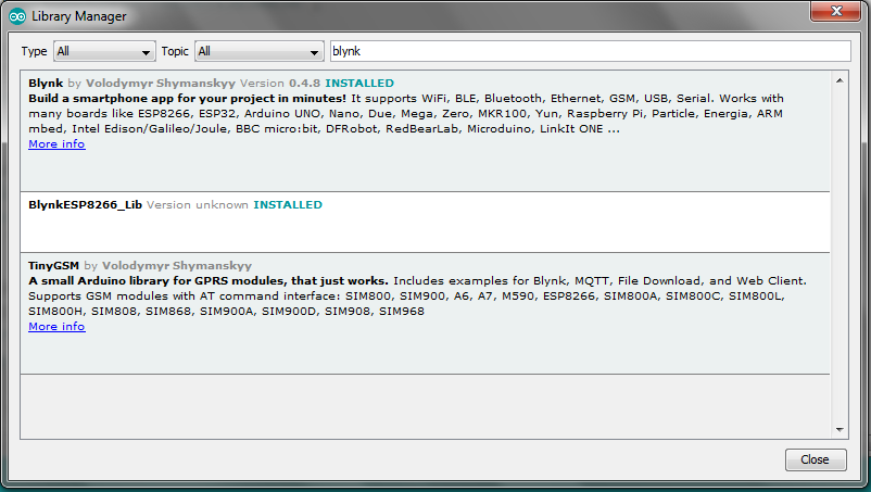
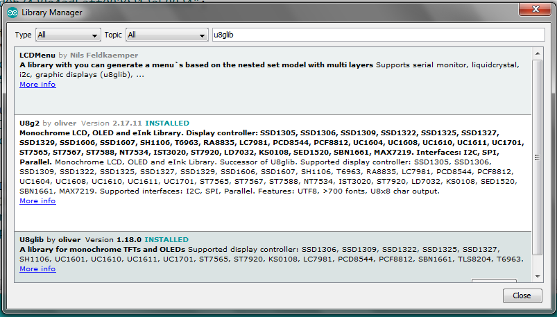
De vereiste bibliotheken installeren:
U moet twee verschillende bibliotheken voor de Arduino IDE hebben geïnstalleerd om de code zonder fouten te compileren. Dit zijn:
- Blynk , om hem met uw smartphone te verbinden
- u8g2lib , voor de weergave
Er zijn twee manieren om de vereiste bibliotheken te installeren. De eerste is via de 'Library Manager' die beschikbaar is in de nieuwere versies van de Arduino IDE, en de tweede is de handmatige installatie. Beide methoden worden hier in detail beschreven, dus bekijk de link, want daar ga ik niet doorheen.
De code uploaden en testen:
Nadat u de bibliotheken hebt geïnstalleerd, downloadt u de bijgevoegde code en brengt u er enkele wijzigingen in aan. U moet uw authenticatiecode van Blynk toevoegen (die naar u wordt gemaild wanneer een nieuw project in Blynk wordt gemaakt), evenals uw WiFi SSID en wachtwoord. Zodra dat is gebeurd, uploadt u de code naar de MKR1000.
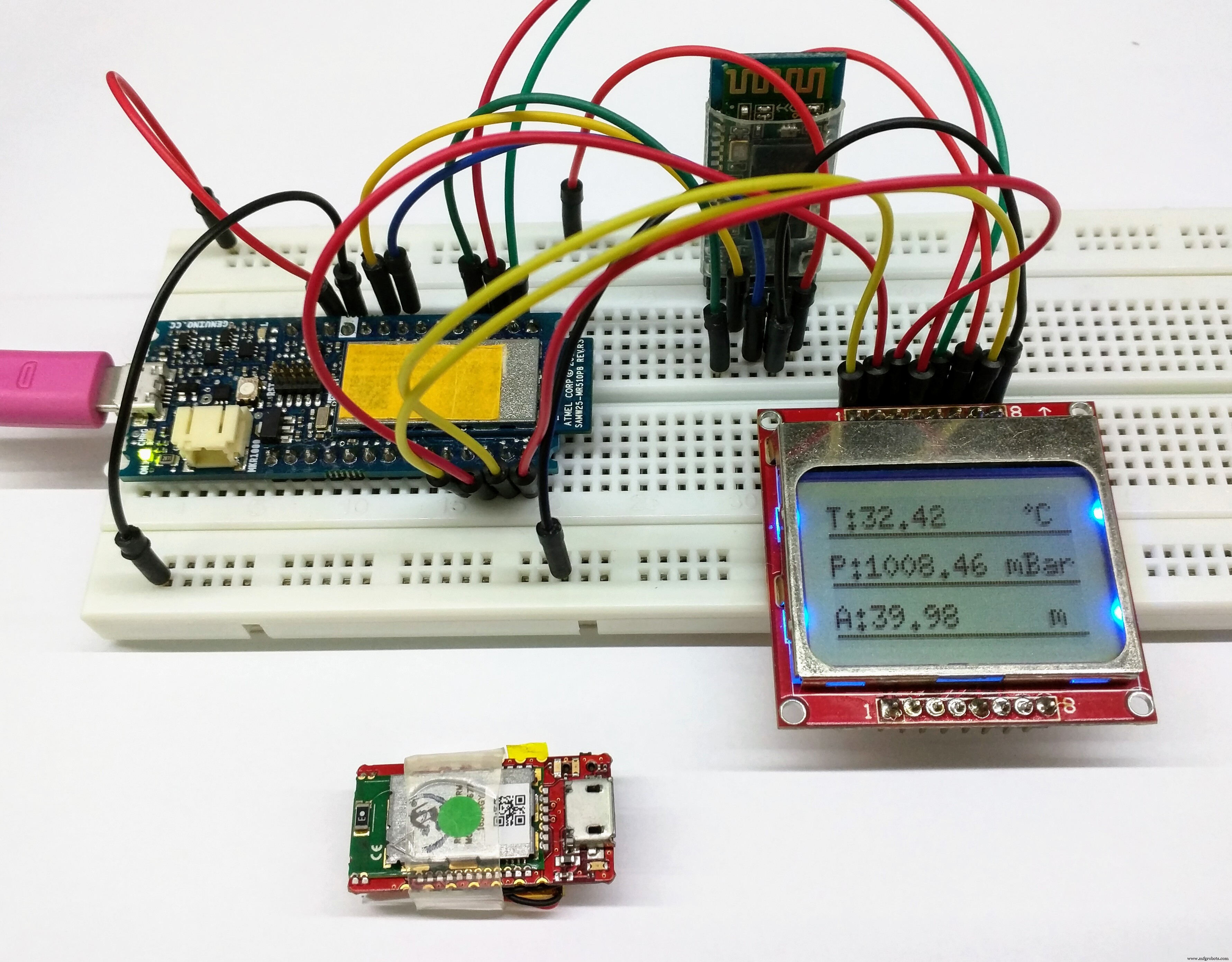
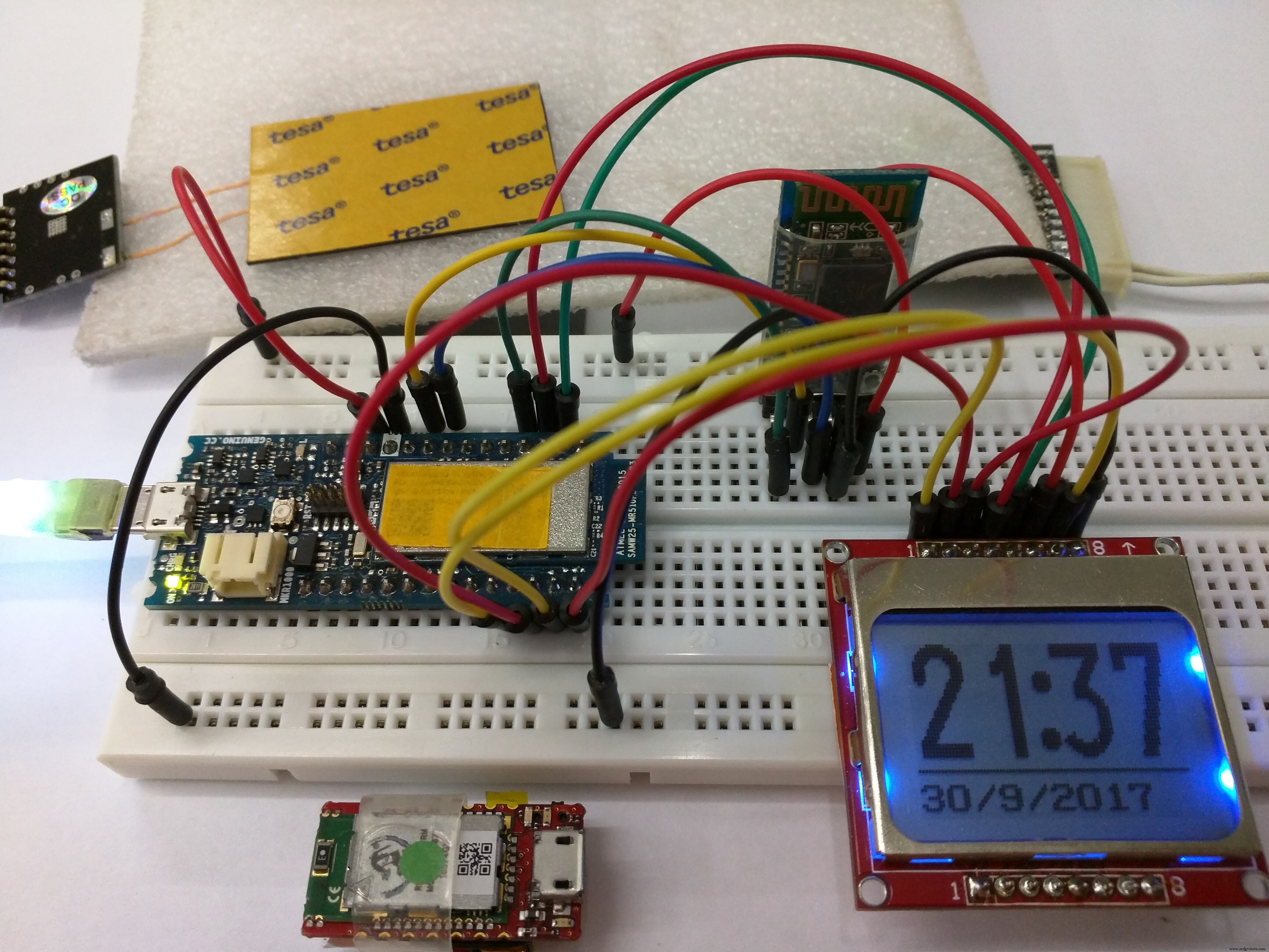
Sluit na het uploaden van de code het circuit aan volgens het schema.

Open vervolgens de Blynk-app in je smartphone, open het Alzheimer Assistent-project en druk op de afspeelknop. Sluit de MKR1000 aan (met de HC-05 en het scherm bedraad), en u zou het logo Alzheimer-assistent op het scherm moeten zien. Het blijft even staan en dan zie je het bericht "Wachten op Sensor Hub Nano ”. Zet de kleine schakelaar op de Sensor Hub Nano aan, zodat u zich binnen het bluetooth-bereik van de HC-05-module bevindt. Er zou moeten staan "Verbonden met Infineon's Sensor Hub Nano ", en na een paar seconden zou u de druktemperatuur en hoogtewaarden op uw smartphone moeten zien.
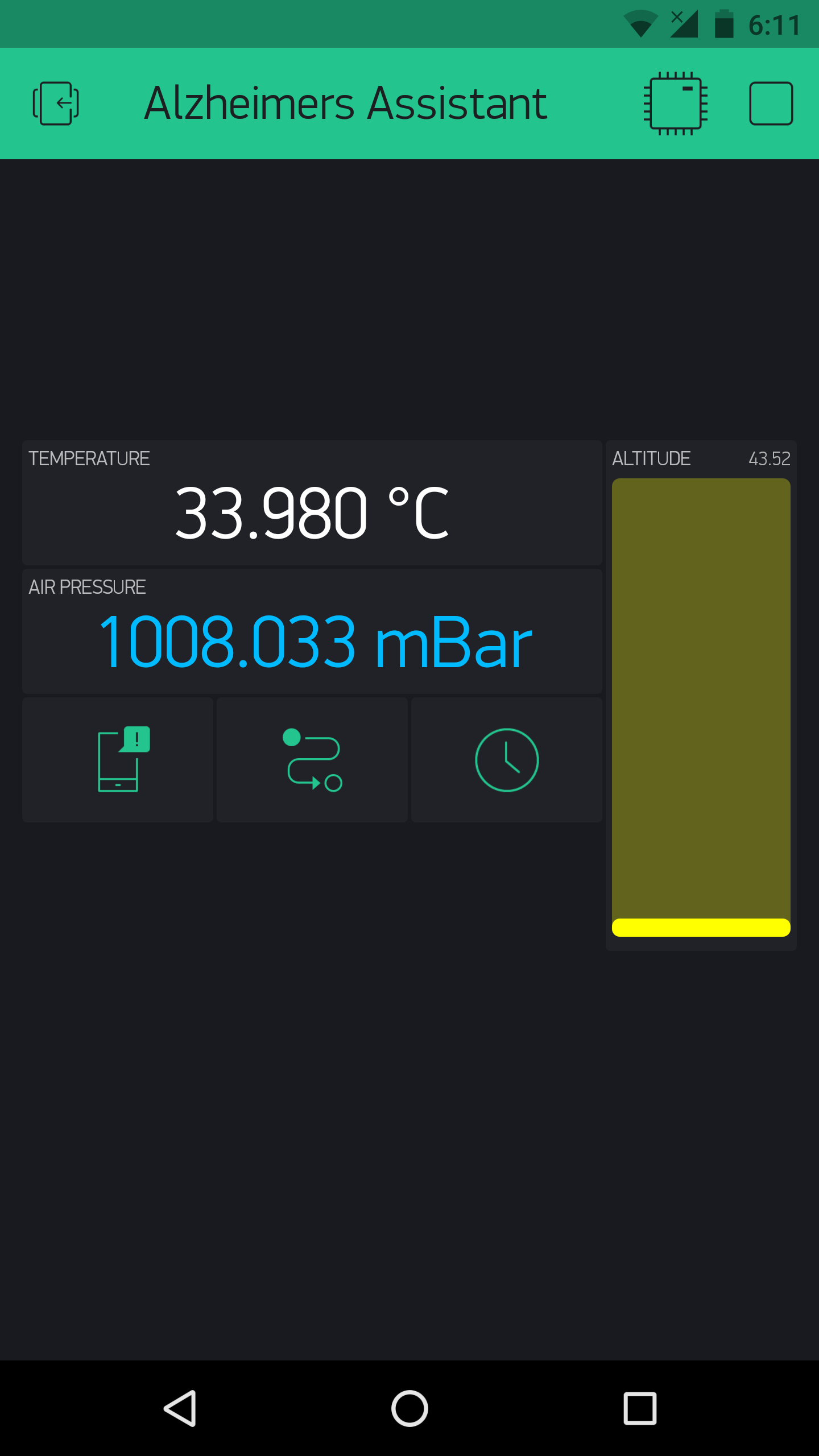
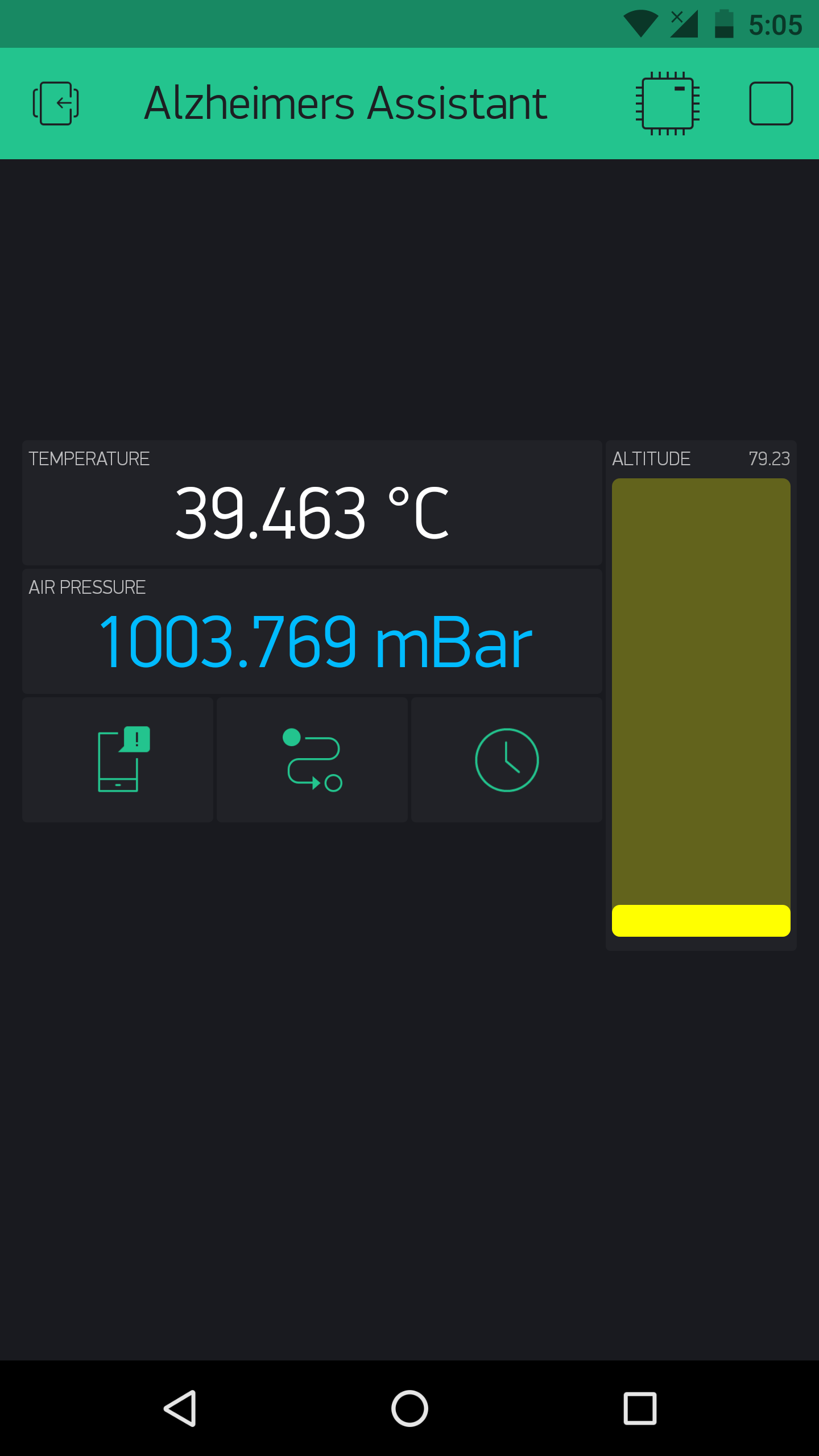
En na een paar seconden zie je ook de tijd in 24-uurs formaat, evenals de datum, en dat synchroniseert met internet.
Dit is een video om het uit te testen:
Zo ja, gefeliciteerd, je hebt het moeilijke deel van het instellen voltooid en nu komt het personaliseren voor individuele patiënten, volgens hun voorkeuren.
Alzheimer-assistent personaliseren
Wat we tot nu toe hebben opgezet, haalt sensorgegevens op van Infineon's DPS310 in een nette en elegante opstelling, maar om er iets nuttigs van te maken, moeten we de opstelling configureren volgens individuele vereisten en voorkeuren. Daarom zal ik in deze sectie praten over de code en hoe de Alzheimer-assistent kan worden aangepast om te werken volgens de voorkeuren van elke gebruiker. Ik zal het codefragment voor elke 'functie' geven en je kunt het eenvoudig toevoegen aan de hoofdcode met een paar kleine wijzigingen.
Opmerking:als je kijkt naar de code die ik heb bijgevoegd voor het 'bare-bones-project', zul je zien dat het functies gebruikt die in de BlynkTimer zijn verpakt. Ik zou een goed idee zijn om ze te gebruiken als je aanpassingen wilt doen, omdat het taken met een bepaald interval kan uitvoeren en ook de Blynk-flood-fout kan voorkomen die optreedt wanneer je hardware veel verzoeken naar Blynk stuurt. Ook is de code 'kaal' in de zin dat alle functies aanwezig zijn, maar niet in de hoofdcode zijn opgenomen; de gebruiker moet de hoofdcode naar behoefte bewerken en moet mogelijk het tijdsinterval aanpassen waarmee elke functie wordt uitgevoerd.
De DPS310:-
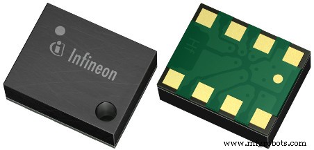
De DPS310 van Infineon is een goedkope digitale luchtdruksensor die een zeer hoge nauwkeurigheid biedt, in een zeer kleine vormfactor. Daardoor is hij perfect te gebruiken in zo'n project en kunnen de waarden gebruikt worden om vallen op te sporen bij een oudere patiënt, of in welke kamer de patiënt zich precies bevindt.
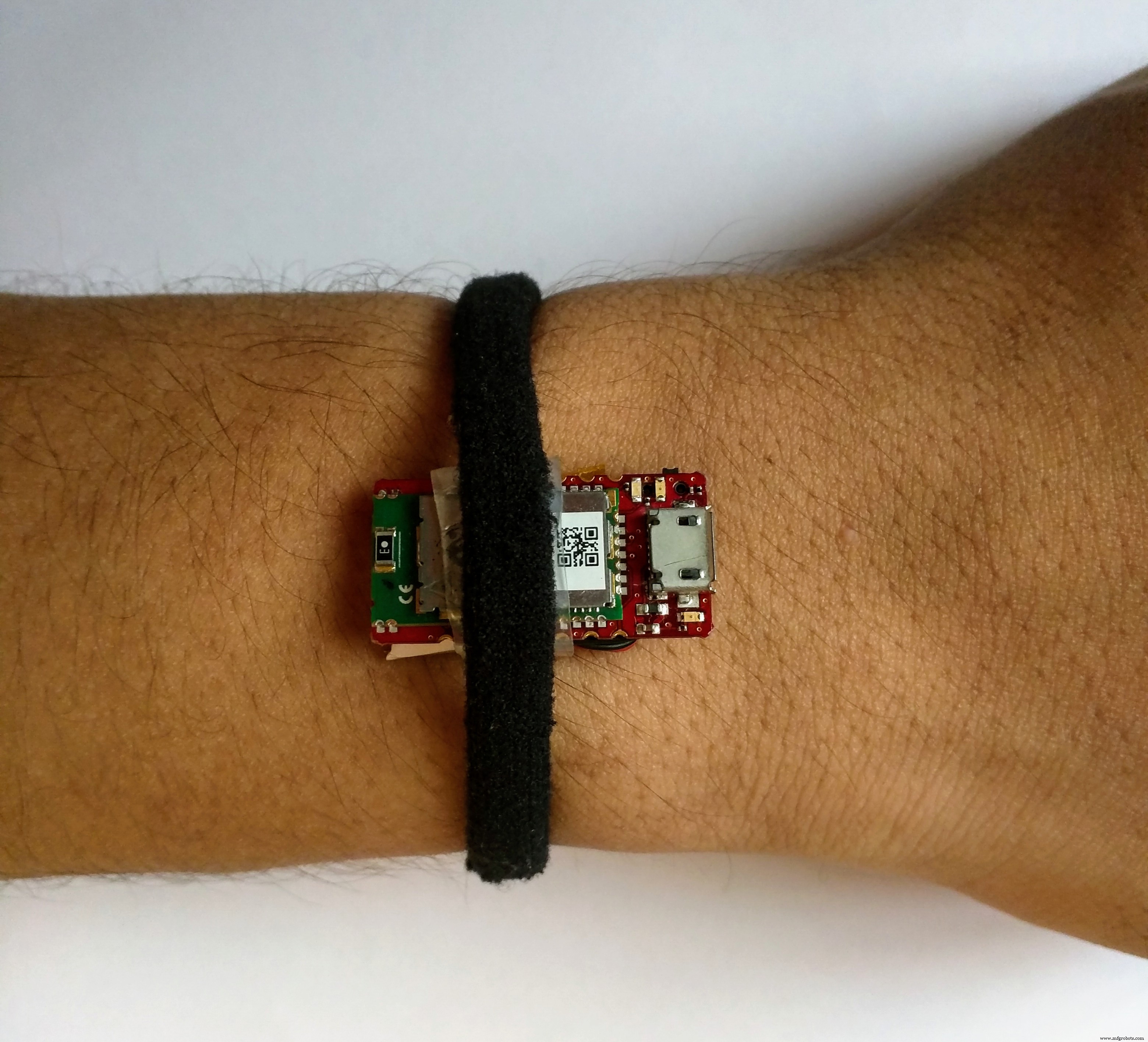
Opmerking:ik heb de behuizing van de smartwatch nog niet gemaakt, dus gebruik ik de Sensor Hub Nano op mijn hand, verbonden met de Arduino via Bluetooth, zoals in deze afbeelding:
Valdetectie: Om vallen te detecteren, moeten we een valwaarde opgeven (het verschil in luchtdruk tussen twee metingen gedurende een bepaalde tijd) en een speling instellen. Als bijvoorbeeld de hoogteverandering tussen twee opeenvolgende waarden (over een tijd van laten we zeggen een seconde) tussen de valwaarde ± de afstandswaarde ligt, wordt een val gedetecteerd.
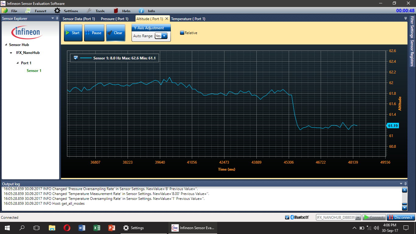
Ik heb een aantal tests gedaan en ontdekte dat de valwaarde 0,7 zou moeten zijn en de vrijgavewaarde ±0,2 zou moeten zijn, maar ze werken mogelijk niet in alle situaties. Dit is te wijten aan een eenvoudige en begrijpelijke reden dat wanneer een persoon valt, dit op veel verschillende manieren kan gebeuren. Daarom zal het gebruik van een secundaire sensor (waarschijnlijk een versnellingsmeter) nodig zijn om meer nauwkeurigheid in het valdetectiesysteem te krijgen, en dat zal worden toegevoegd aan het toekomstige werk. Maar het zou altijd mogelijk kunnen zijn dat er andere, nauwkeurigere algoritmen zijn om vallen te detecteren, en ik sta open om ze te horen; voel je vrij om te reageren als je hier ideeën over hebt.
Een video waarin valdetectie wordt gedemonstreerd:
Detecteren waar de patiënt is: Dit werkt op dezelfde manier als het valdetectie-algoritme. Als u bijvoorbeeld wilt weten op welke verdieping de patiënt zich bevindt, kunt u de huidige hoogtewaarde nemen en deze van de vorige aftrekken. En vergelijk vervolgens het verschil met een vooraf gedefinieerde waarde. Dit geeft aan op welke verdieping de patiënt zich bevindt.
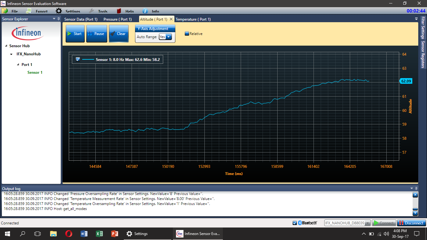
Het zou gewoon een kwestie zijn van het gebruik van eenvoudige logica als en anders om te bepalen op welke verdieping de patiënt zich bevindt (Hoogtewaarden zijn al aanwezig in de hoofdcode). Dat zou kunnen worden aangegeven met behulp van de LED-widgets in Blynk.
Opmerking:ik heb de locatiedetectie niet in de hoofdcode opgenomen, maar gebruikers kunnen deze indien nodig toevoegen, vergeet alleen niet om deze als een Blynk-timerfunctie te gebruiken.
Dezelfde techniek zou ook kunnen worden gebruikt om te detecteren in welke kamer een persoon zich bevindt. In dat geval zou een secundaire sensor zoals een bewegingssensor nodig zijn, anders zouden er veel valse triggers kunnen zijn.
Temperatuur: De DPS310 toont ook de temperatuurwaarde die we kunnen gebruiken om ons te waarschuwen voor elk ongeluk dat de patiënt kan overkomen, bijvoorbeeld een brand. Als de temperatuur stijgt tot een bepaalde waarde, laten we zeggen 45℃, wordt de huismeester gewaarschuwd.
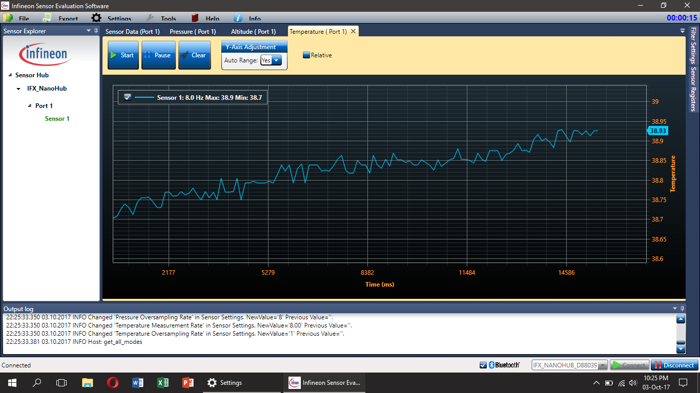
Maar omdat de DPS310-sensor niet rechtstreeks op de huid is bevestigd (althans in deze use-case), krijgen we niet de lichaamstemperatuur, maar het zou nauwkeuriger zijn om te zeggen dat het de temperatuur van de Sensor Hub Nano is.
De code hiervoor is heel eenvoudig (gebruik het overal in de hoofdlus) en zou zoiets als dit kunnen zijn:
if (t> maxTemp) {
 //Doe wat je wilt als de temperatuur hoger is dan het maximum
}
else {
 //Doe wat je wilt als de temperatuur lager is dan het maximum
}
Opmerking:alle bovenstaande grafieken zijn gemaakt met SESG2-evaluatiesoftware van Infineon.
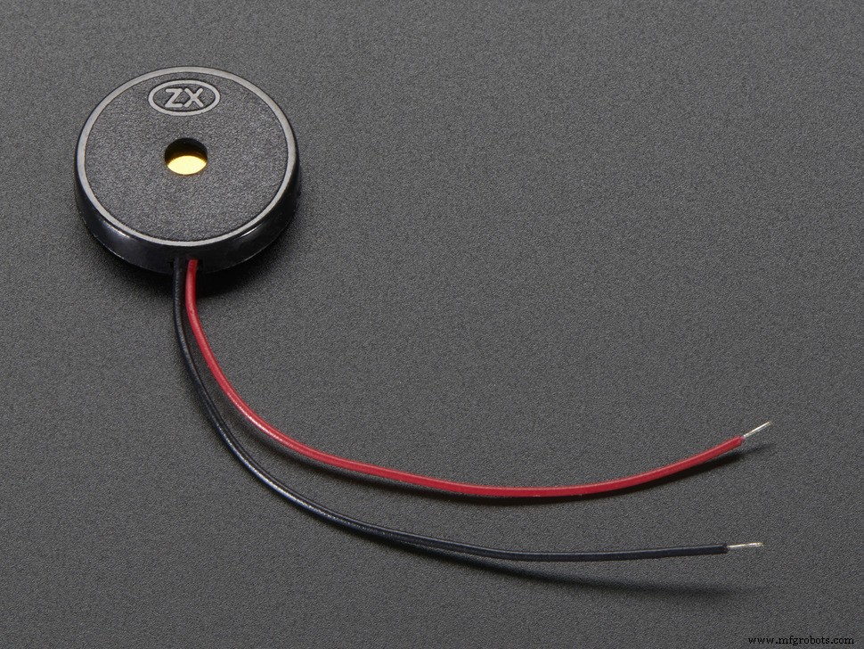
Een zoemer en een schakelaar:-
Ik heb dit nog niet eerder genoemd, maar een zoemer en een schakelaar moeten ook in het systeem aanwezig zijn en ze zullen ook erg nuttig zijn. Een zoemer kan bijvoorbeeld worden gebruikt om de aandacht van de patiënt te trekken, wanneer het bijvoorbeeld tijd is om medicijnen in te nemen, en de schakelaar kan worden gebruikt als veiligheidsvoorziening.
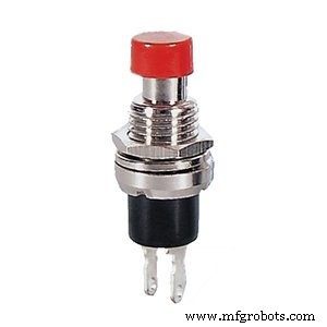
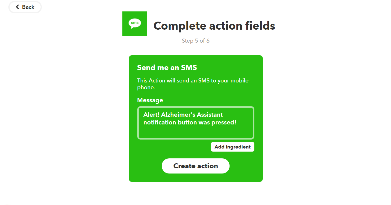
En omdat we Blynk gaan gebruiken, kan de knopschakelaar zo worden ingesteld dat wanneer erop wordt gedrukt, er een melding op de telefoon van de beheerder verschijnt of dat hij belt of een sms stuurt (dat kan met IFTTT en wordt later gegeven ). Dit kan het codefragment zijn om dat te doen:
void emailOnButtonPress()
{
 // *** WAARSCHUWING:U mag SLECHTS ÉÉN E-MAIL PER 15 SECONDEN verzenden! ***
 // Laten we een e-mail sturen wanneer u op de knop drukt
 // aangesloten op digitale pin 2 op uw Arduino
 int isButtonPressed =!digitalRead(2); // Status omkeren, aangezien de knop "Actief LAAG" is
 if (isButtonPressed) // U kunt elke voorwaarde schrijven om het verzenden van e-mail te activeren
 {
 Serial.println ("Knop is ingedrukt ."); // Dit is te zien in de seriële monitor
 Blynk.email("[email protected]", "Subject:Button Logger", "Je hebt zojuist op de knop gedrukt...");
 // Of, als je het e-mailadres wilt gebruiken dat in de App is gespecificeerd (zoals voor App Export):
 //Blynk.email("Subject:Button Logger", "Je hebt zojuist op de knop gedrukt. ..");
 }
}
Het is afkomstig uit de Blynk-voorbeeldcode en gebruikt een onderbreking om de knop te controleren. Dit kan door de patiënt worden gebruikt om de verzorger te waarschuwen in een noodsituatie, zoals een val die niet werd gedetecteerd door het valdetectie-algoritme. Je kunt hier de volledige voorbeeldcode krijgen, die een e-mail stuurt zodra er op een knop wordt gedrukt.
De zoemer kan worden gebruikt om tonen te produceren (met behulp van de Arduino tone()-opdracht - meer informatie hier), om de patiënt te herinneren aan een taak zoals medicatie of inspanning.
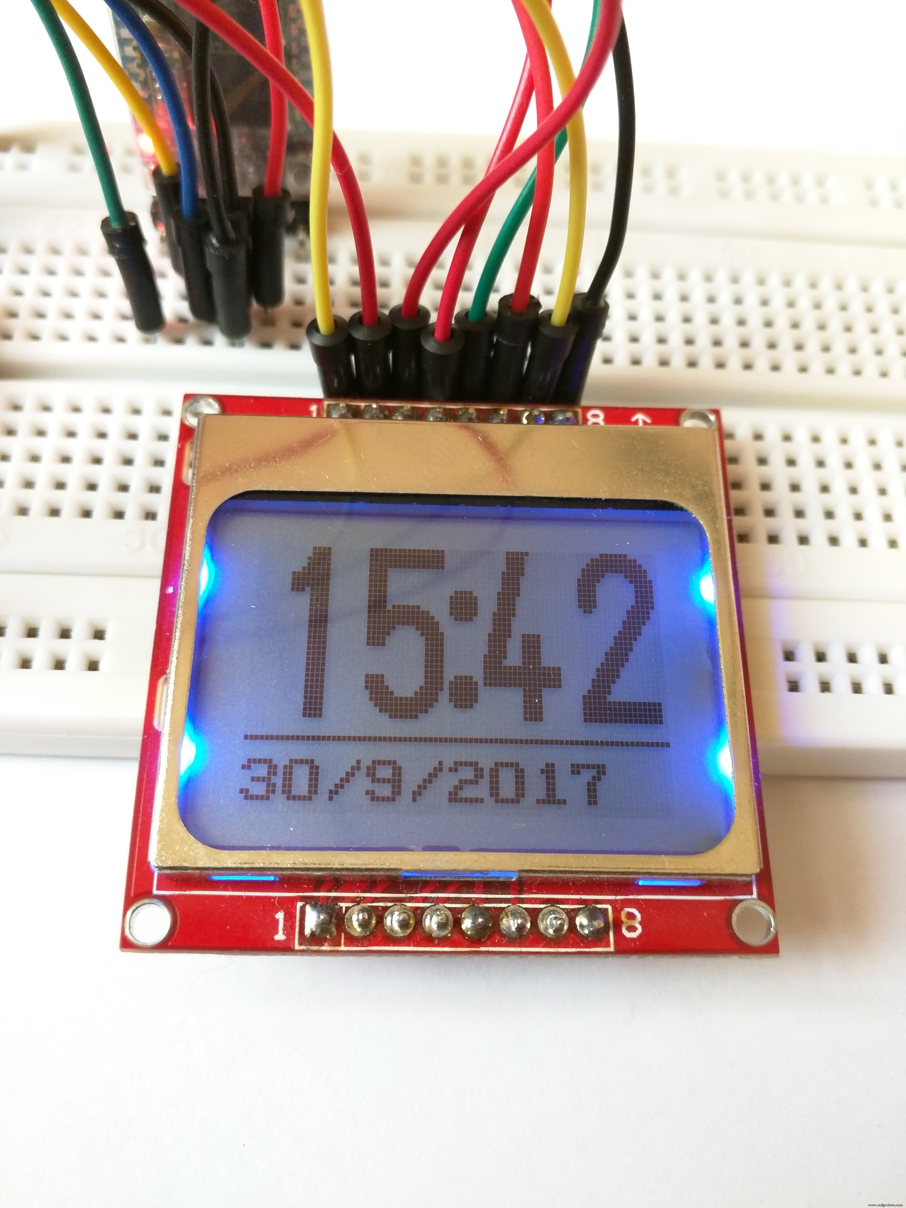
Het scherm:-
Een belangrijk onderdeel van het project, waar de gebruiker daadwerkelijk naar kijkt, is het display. De Nokia 5110-schermen zijn algemeen verkrijgbaar, eenvoudig in te stellen en goedkoop, maar ze zijn niet zo flitsend, vooral niet wanneer ze in een dergelijk systeem worden gebruikt. OLED-schermen met een hogere resolutie zijn hiervoor een zeer goed alternatief, en je kunt de code eenvoudig aanpassen om ermee te werken, omdat ik de u8g2-bibliotheek heb gebruikt (github hier). Choose any of the display models from here, and add it to the start of the sketch (removing the Nokia 5110 line, of course!). You will need to wire it up according to what it is in the code and you’re ready to go. You can also use bitmap images with a higher resolution display. You can also change the font for the text on the display, select fonts from the huge list here and edit the name of the font in the code.
Note:You may have to change the pixel positions for the text in the code if you use a display with a higher resolution.
That was just a brief description of the library used to get the display working. But, now I will tell you how to edit the code to get Alzheimer's Assistant to show the time or the Sensor Hub Nano data (temperature, Altitude and pressure).
Displaying time: To display the time, you could simply use an RTC (or time keeping module) but as we're connected to the Internet, it would be much more easier to use the Internet to sync the time. And as we're using Blynk that would make it even more simpler. You just need the RTC widget in your project. Now with a few lines of code, you can automatically retrieve the time from the Blynk server (Make sure to set your timezone from the Blynk widget). The main code is set to display the time by default (not the sensor values, discussed next)
Note:The time displayed on the screen could go up or down a minute, as it is synced from the internet, but despite that, I have tested it for a long time and have found it to be very accurate (just a difference of a few seconds).
Displaying the Sensor Hub Nano data: We could just as well display data from the Sensor Hub Nano in the display. Not that it would benefit the patient, but its good for debugging purposes, should you need it. That can be done with the following code snippet:
void showSensorValues() {
 //Shows the sensor values on the display
 char bufT[10];
 char bufP[10];
 char bufA[10];
 String(t).toCharArray(bufT, 10);
 String(p).toCharArray(bufP, 10);
 String(a).toCharArray(bufA, 10);
 u8g2.clearBuffer();
 u8g2.setFont(u8g2_font_6x10_tf );
 //Display the temperature
 u8g2.drawStr(0, 10, "T:");
 u8g2.drawStr(12, 10, bufT);
 u8g2.drawStr(73, 10, "C");
 u8g2.drawCircle(70, 4, 1, U8G2_DRAW_ALL);
 u8g2.drawHLine(0, 12, 85);
 //Display the pressure
 u8g2.drawStr(0, 26, "P:");
 u8g2.drawStr(12, 26, bufP);
 u8g2.drawStr(60, 26, "mBar");
 u8g2.drawHLine(0, 28, 85);
 //Display the altitude
 u8g2.drawStr(0, 42, "A:");
 u8g2.drawStr(12, 42, bufA);
 u8g2.drawStr(72, 42, "m");
 u8g2.drawHLine(0, 44, 85);
 //Send the values to the display
 u8g2.sendBuffer();
}
Don't forget to run this command to get the sensor data below:
getSensorValues(); But that's not all for the display. As I said in the start, Alzheimer's Assistant should be able to remind the patient of the tasks which need to be done daily, such as when to take medications or to remind the patient to exercise.
Using Eventor widget to remind:-
For that, we will be using the Eventor widget (check here for details) in Blynk.
Add the Eventor widget into your project (It's already there if you scanned the QR code above), and just follow the screenshots to see how to set it up:
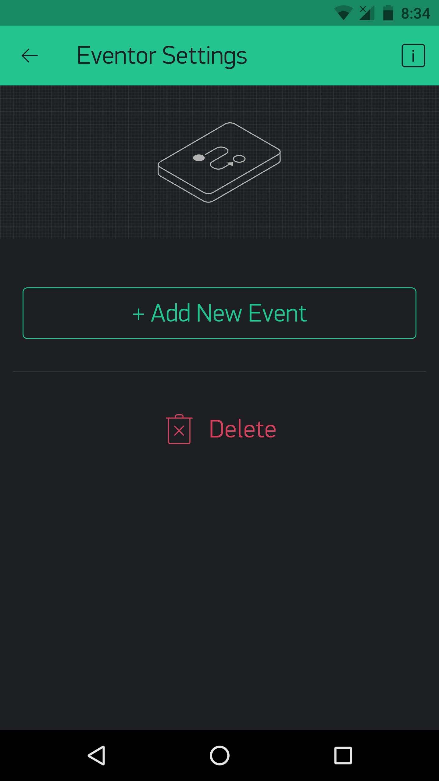
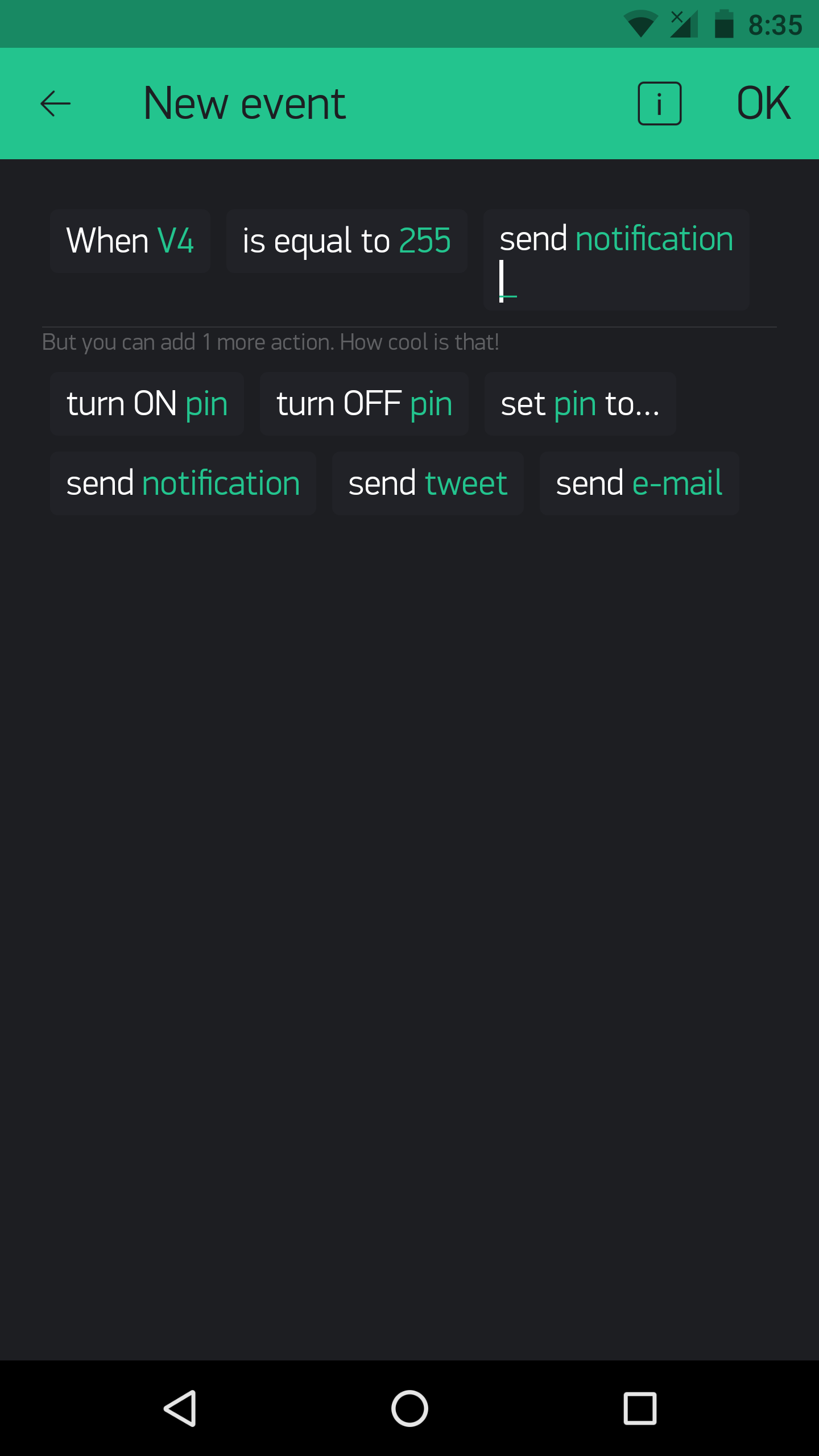
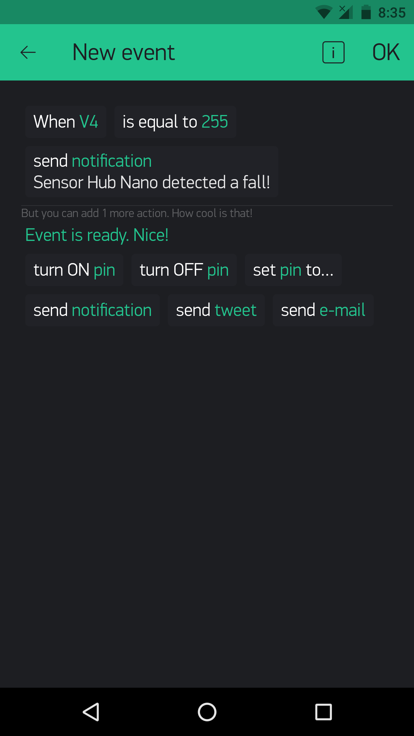
In the above example, the Eventor widget is used to set up a fall detection notification.
Using the Eventor widget to remind is done by this code:
BLYNK_WRITE(vEVENTOR_PIN) {
 //Use the Eventor widget to check if it's time to do a task (take medication in this case)
 int currentValue =param.asInt(); // 0 to 1
 if (currentValue ==1) {
 //Do here what you want to when its time for medication
 showPillReminder();
 playBuzzerReminder();
 //This is just a tone, I haven't made it in the main code, but you can if you want!
 }
 else {
 //If it's not the time for medication, do nothing
 }
}
And the result on the display when it's the time for medication:
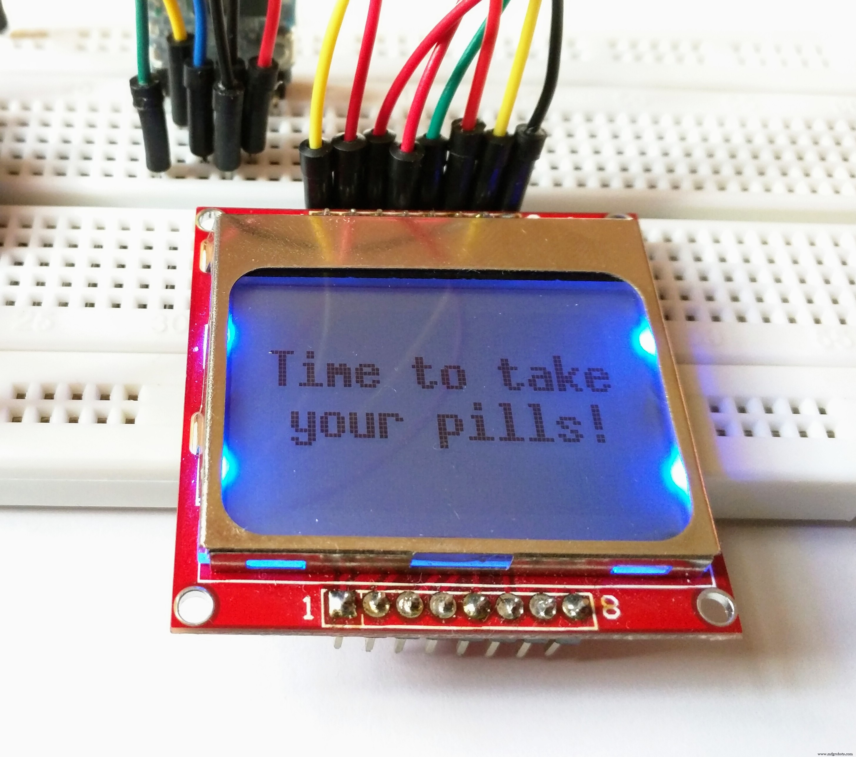
The same for exercise:
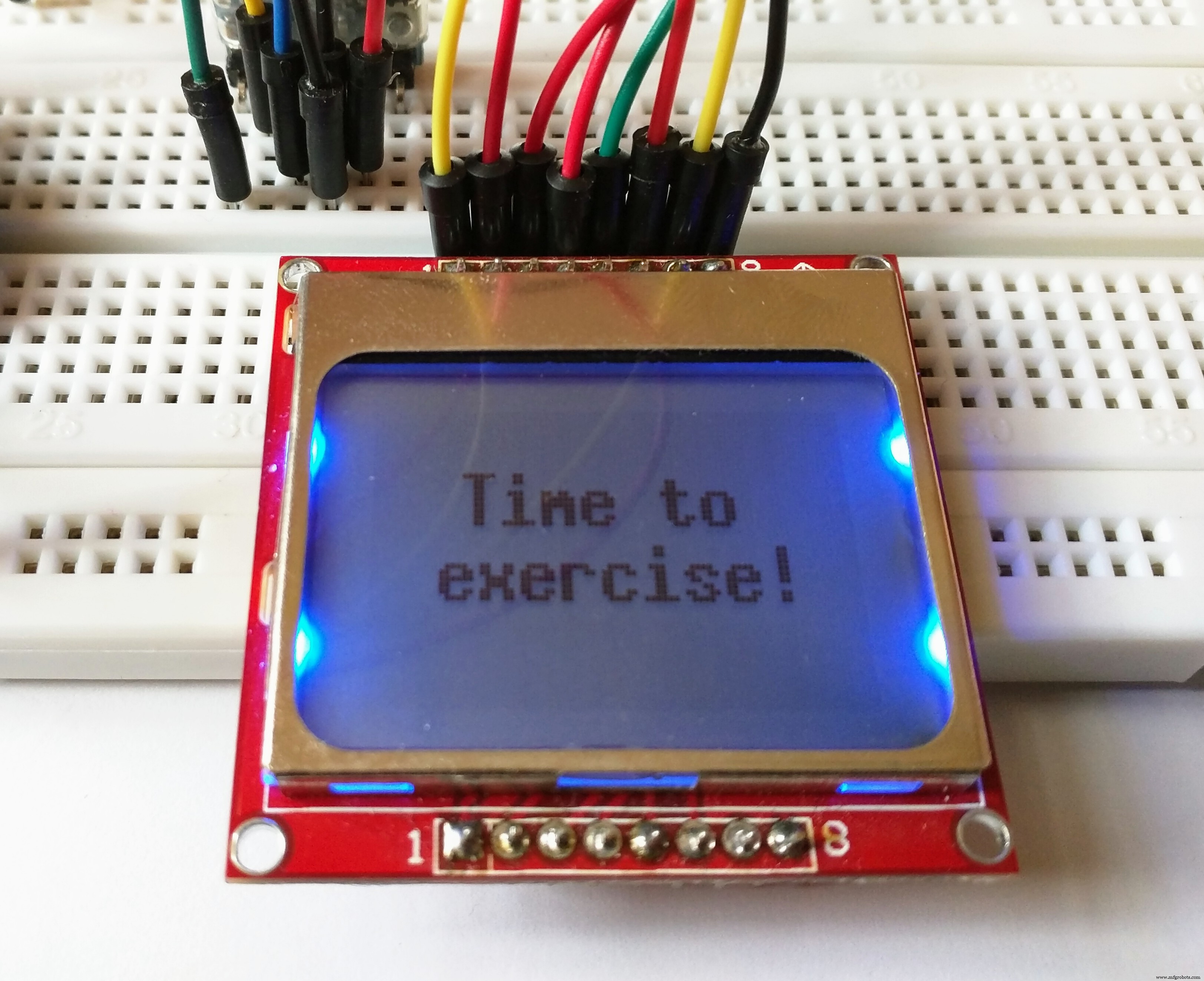
This is done by typing:
showExerciseReminder(); Instead of:
showPillReminder(); The eventor widget could, as said above, be used for a number of things. For example, you could set that an increase in temperature could result in sending an e-mail, and with no code modification!
Using different modes of the Sensor Hub Nano:-
You can test out the use of different modes for the Sensor Hub Nano. Using the following commands:
sendCommand(LOW_ENERGY);
sendCommand(STANDARD_MODE);
sendCommand(HIGH_PRECISION);
Using Blynk to switch modes could be more efficient. For that, set up your Blynk app like this:
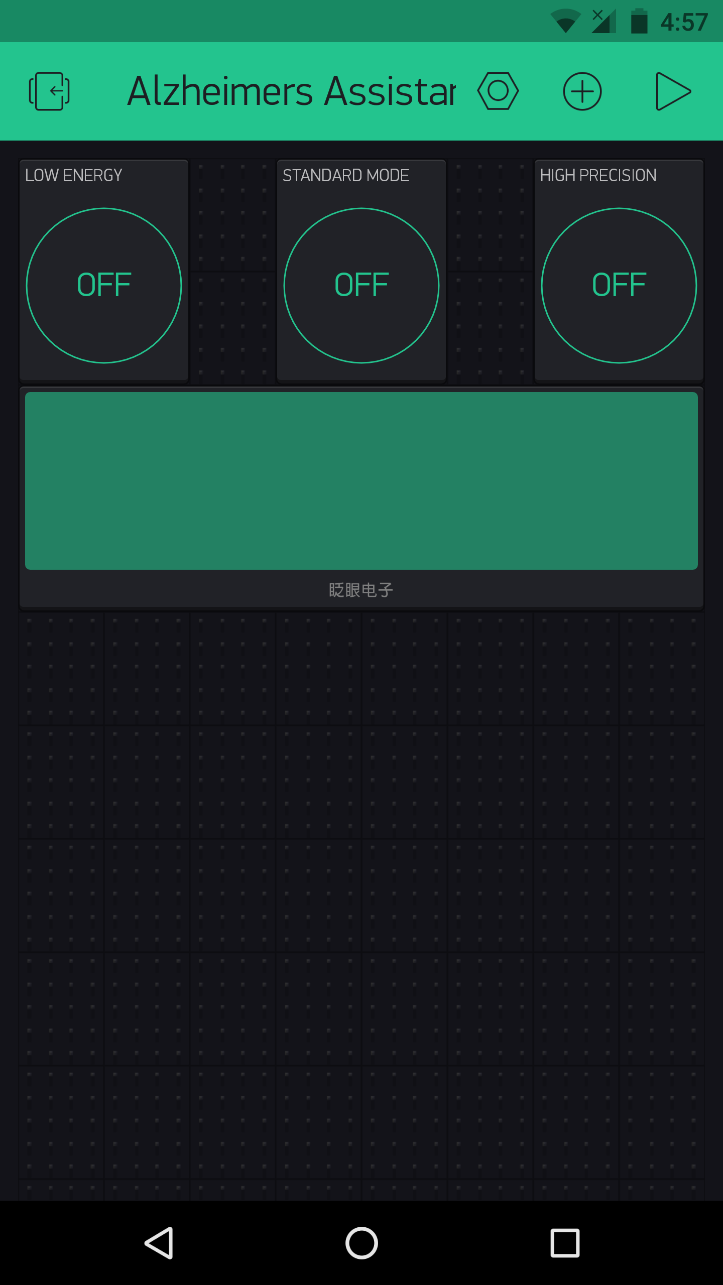
As this had no use for me, I did not add it it in the main code, but you could always do so as needed (The commands are present, you just need to add them with a bit of logic in the main sketch).
Using Blynk and IFTTT:-
Blynk can allow any Arduino project to easily harness the power of IFTTT.

This is because you can use Blynk to send a webhook request to the IFTTT Webhooks channel (previously called Maker channel), and you could create an IFTTT applet which waits for the webhook to be triggered (from the Blynk and Arduino side) and you could get it to trigger anything else in response to that.
A simple example on how to use IFTTT and Blynk with webhooks :
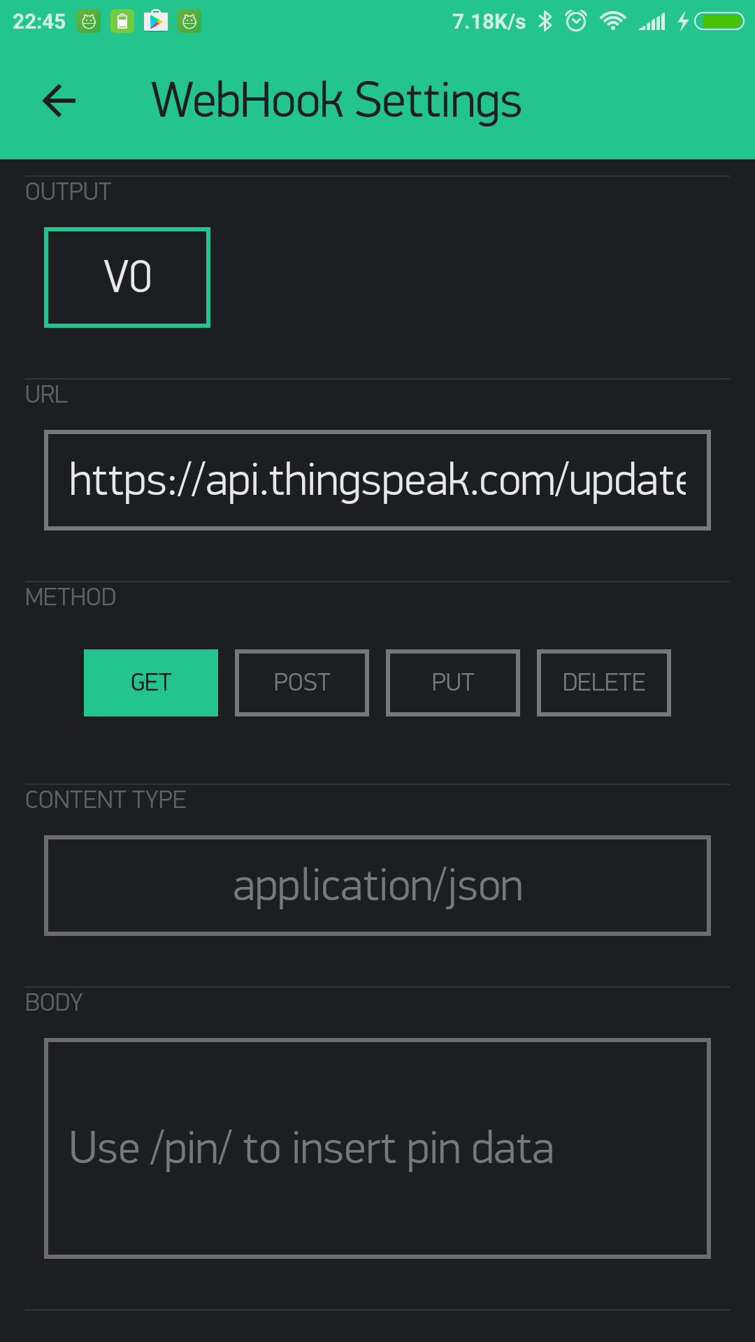
The Blynk webhook widget could be used to send a webhook request like this:
This is the IFTTT webhook channel:

And using webhooks to trigger IFTTT is not the only method. IFTTT can also be triggered by using Blynk to send emails and tweets.
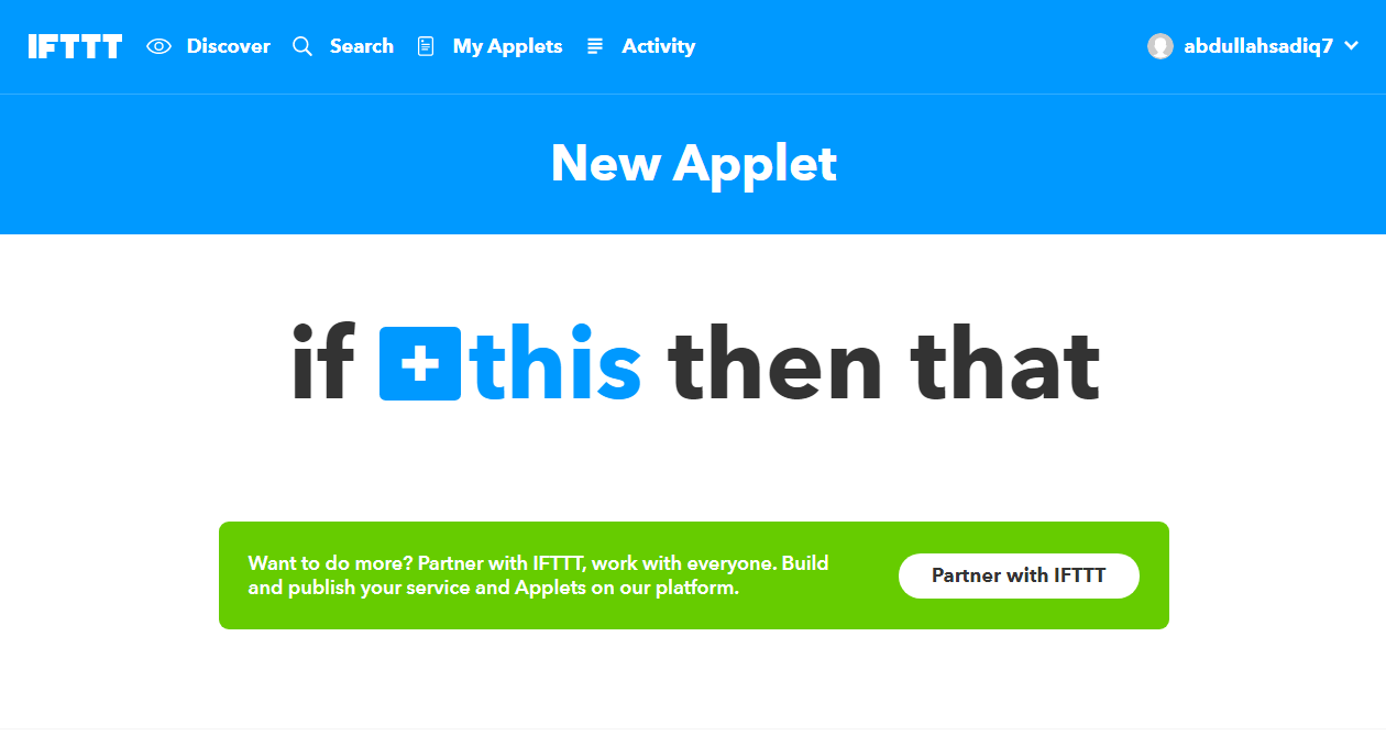

You have now made an applet. Time to test it.
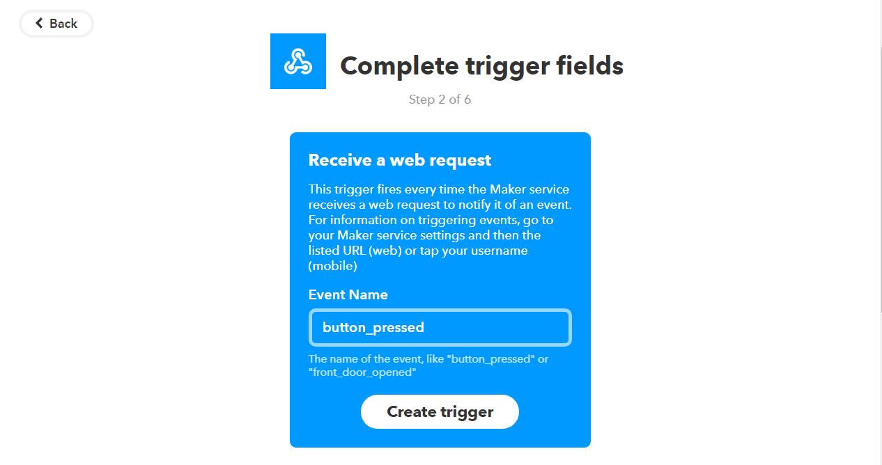
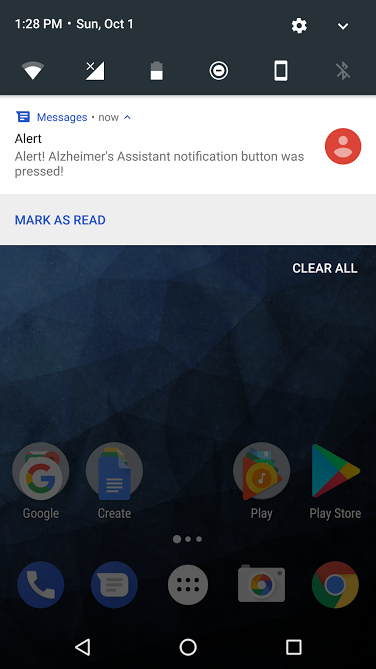
Open "Services" in IFTTT and then select "Webhooks". Go to "Settings" and there you will see a URL. Copy that and open it in a new tab. There, instead of {event}, type the event name (which you set earlier). That was "button_pressed" for me, and so when I click on "Test it", this is the result after a few seconds:
Now that you have confirmed the Webhook works, you can just write the URL in the Blynk webhook settings and get a GET or POST request (through the Blynk webhook widget)
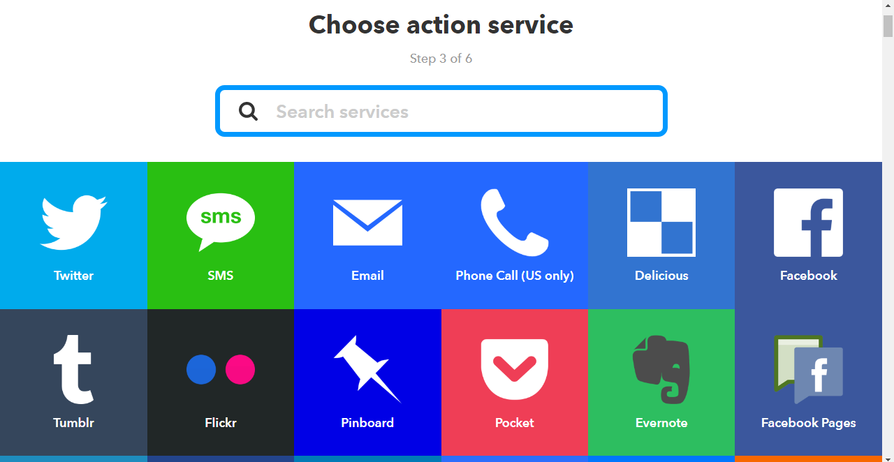
And, instead of SMS, you could just as well use phone calls, or even Twitter and Facebook, if you want, and it's just as simple That is the power of IFTTT.
It's the same thing as my smart home controller project here, and I also discussed it in detail there, but it is a great thing which I couldn't go by without mentioning.
Final Touches
By now, almost all of the electronics part of the project is complete, but a few things still remain. Read on for them, and in the end, I will list the future work which should be done to improve this project.
Battery and charging:
The MKR1000 has a port for a LiPo battery, which means you could attach one. But I don't have one at the moment so I will not be going into that but you should check out the website for the Arduino MKR1000 if you need information on that.
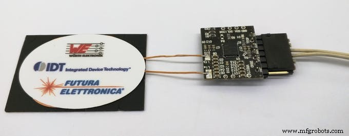
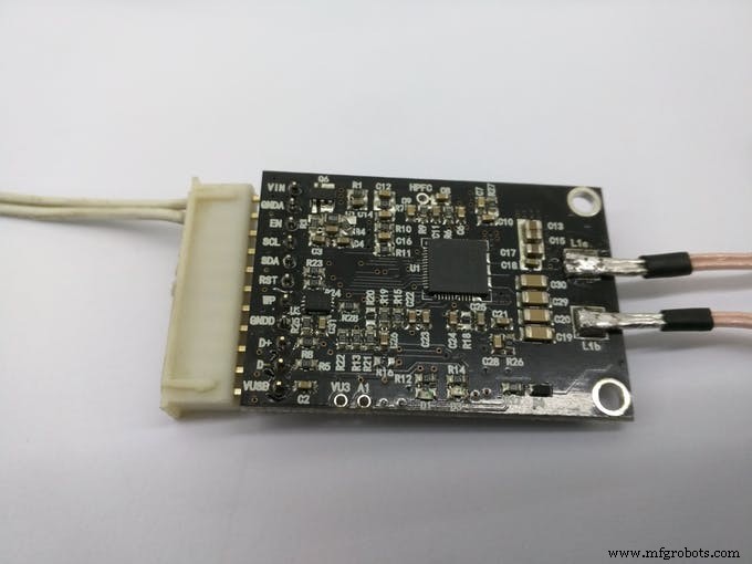
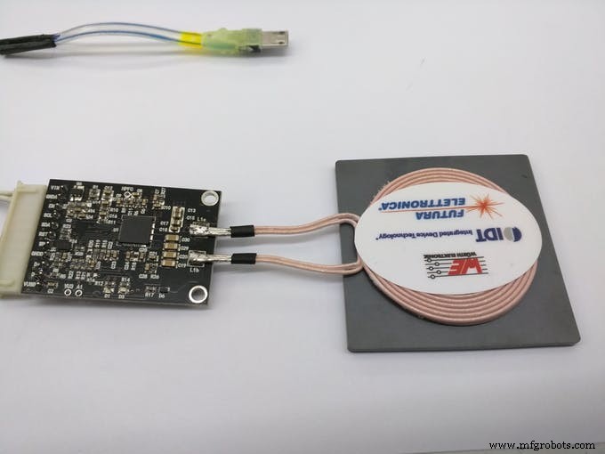
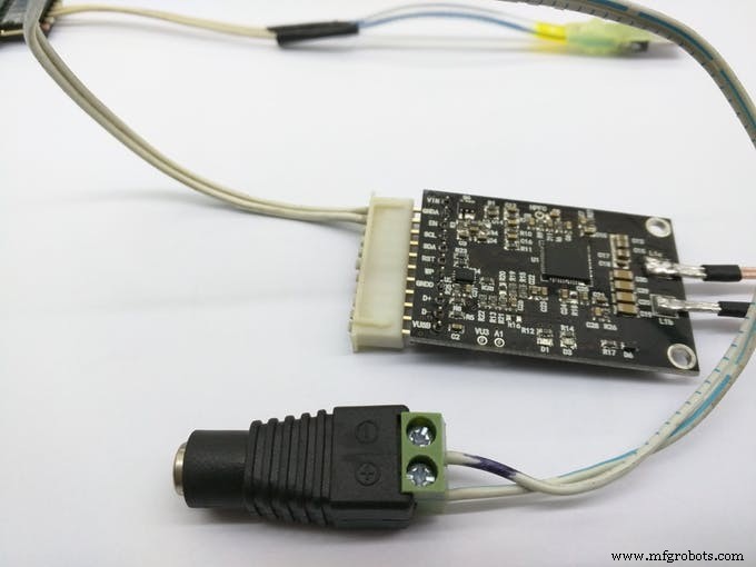
For charging, you have two options, using the MKR1000 USB port directly, and the other one is to use wireless charging, if you have it. I will be using the wireless charging for it. This is because I already have a wireless charging receiver and transmitter made by Futara Elettronica.
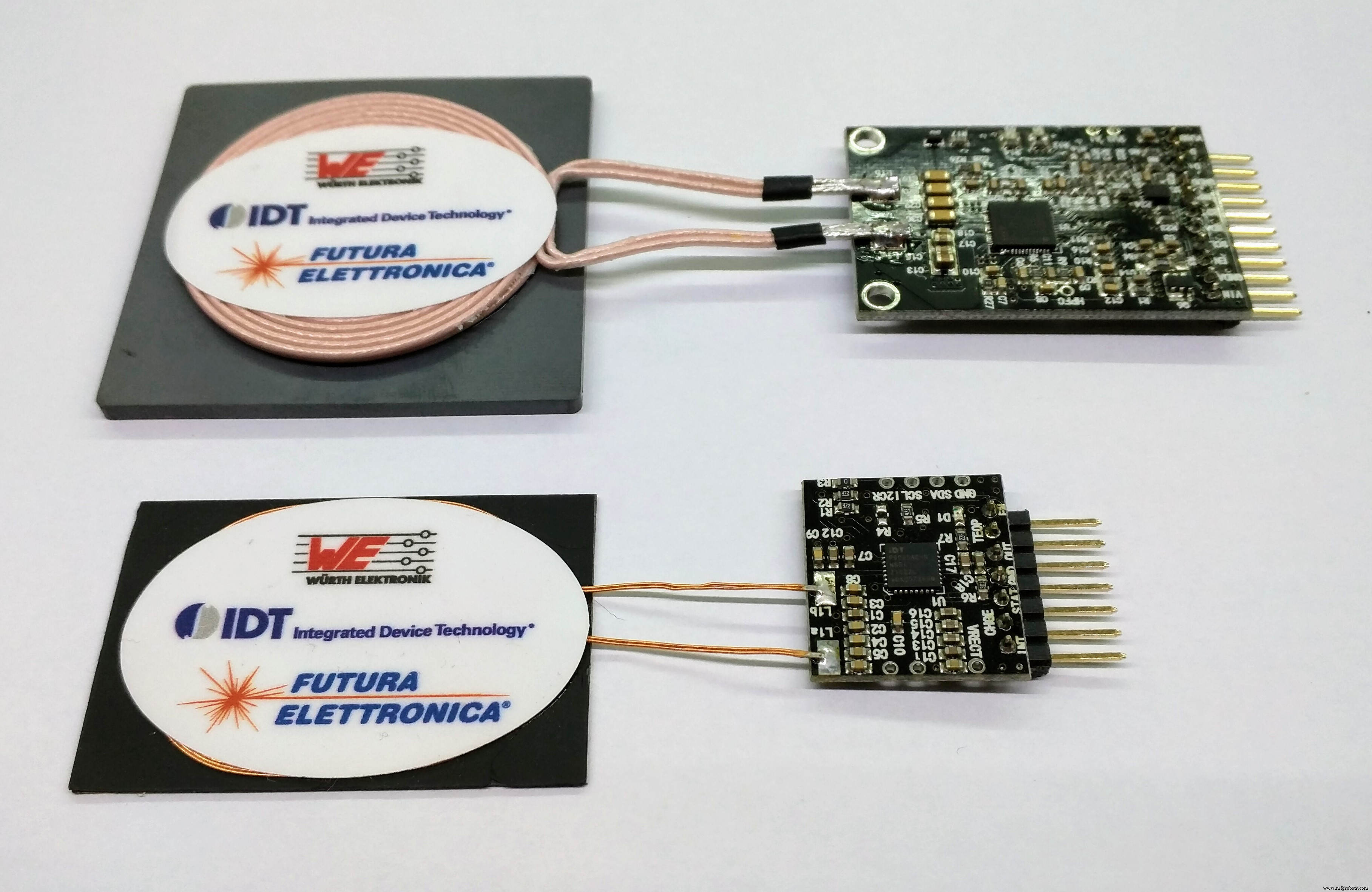
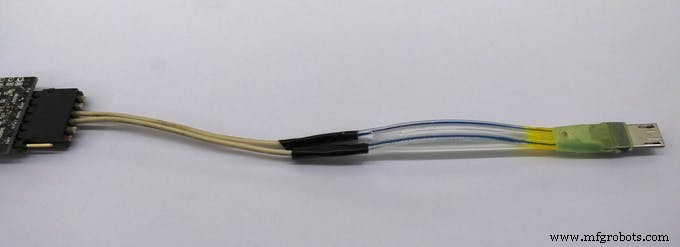
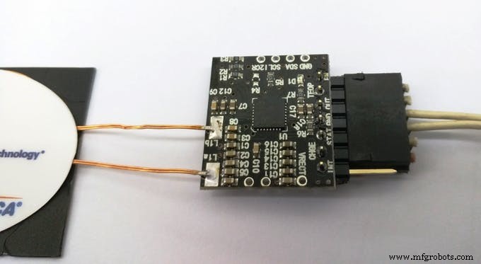
To use the receiver and transmitter, it's just a simple matter of providing the specified voltage to the transmitter. That will be the 'dock', where you can place Alzheimer's Assistant to charge. At the receiver side, you will just have to cut and attach a spare USB micro B cable (which goes to the MKR1000 USB port) and connect the other side to VCC and ground by looking at the pinout.
Just look at the images below to see how to wire it up:
And the end result:
The Enclosure:
As with every project, an enclosure is required for this too, and this how I intend Alzheimer's Assistant to look like:
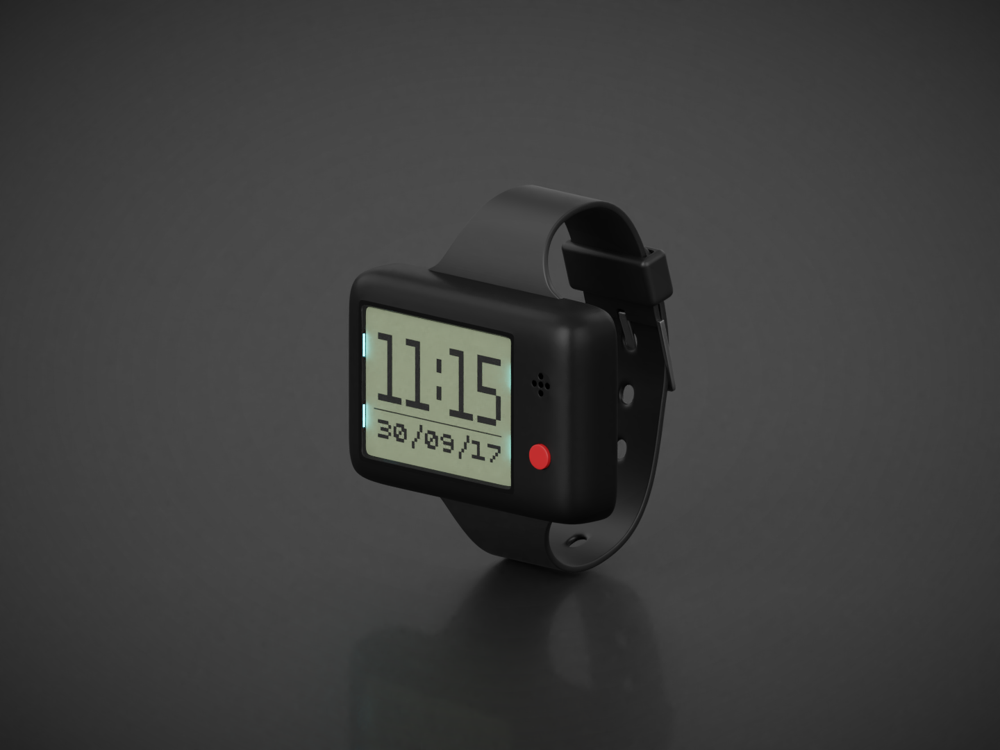
Note:I do not yet have the privilege of a laser cutter or 3D printer, so the STL file is just intended for showing how the final project looks like and it's not to scale.
This concludes the documentation for Alzheimer's Assistant, but I would still like to include the future work section to describe the things which I very much wanted to do for the project, but couldn't, due to some reason or the other.
Future work:
As I said before, these are the things which I wanted to include in the project, which I will add in future, should I get the time:
- Making a proper enclosure for it. Now I am just testing it on a breadboard but if I get access to a laser cutter or 3D printer I will update the documentation with that.
- Using a Bluetooth 4.0 module instead of this one.
- Or even better, using just the DPS310 Sensor instead of the Sensor Hub Nano. This would decrease the cost for the project overall, as it will eliminate the use of the Sensor Hub Nano and the bluetooth module; the DPS310 itself is a available for cheap. It's a matter of editing the main code to get temperature, pressure and altitude values from the DPS310 only, the rest of the part is done.
- Using a secondary sensor to work along with the DPS310 for fall detection and the location detection. This would decrease the occurrence of both, false positive and false negative alerts. Most probably an accelerometer and a motion detector will be needed for both.
- Adding a pulse sensor. I did not have one, so I couldn't add that. It should be a great addition to the project.
- Using a higher resolution display, preferably an OLED. With that, graphics can also be included and that would be pretty neat.
- Working on improving the battery life for the project. This can be done by using a deep sleep mode in the MKR1000, but I haven't used it in the code yet.
Thanks for reading, and hope you liked my project. Feel free to give me your opinions and ideas about the project.
Code
- AT Commands
- Alzheimer's Assistant
AT CommandsArduino
This code is used to configure the HC-05 in AT mode. Details on how to get in AT mode are given in the project description// Original sketch from Martyn Currey's blog here:// http://www.martyncurrey.com/arduino-with-hc-05-bluetooth-module-at-mode///// Sketch modified by me to work with Arduino MKR1000!//// Basic Bluetooth sketch// Connect the HC-05 module and communicate using the serial monitor//// The HC-05 defaults to commincation mode when first powered on.// Needs to be placed in to AT mode// After a factory reset the default baud rate for communication mode is 38400char c =' ';void setup() { // start the serial communication with the host computer Serial.begin(9600); Serial.println("Arduino with HC-05 is ready"); // start communication with the HC-05 using 38400 Serial1.begin(38400); Serial.println("Serial1 started at 38400");}void loop() { // Keep reading from HC-05 and send to Arduino Serial Monitor if (Serial1.available()) { c =Serial1.read(); Serieel.schrijven(c); } // Keep reading from Arduino Serial Monitor and send to HC-05 if (Serial.available()) { c =Serial.read(); // mirror the commands back to the serial monitor // makes it easy to follow the commands Serial.write(c); Serial1.write(c); }} Alzheimer's AssistantArduino
The main code for the project, used once you've configured and got the HC-05 to work with Sensor Hub Nano//Including required libraries#include#include #include #include #include #include // You should get Auth Token in the Blynk App.// Go to the Project Settings (nut icon).char auth[] =""; //Enter your Blynk auth token here// Your WiFi credentials.// Set password to "" for open networks.char ssid[] ="";char pass[] ="";//Defining Sensor Hub Nano board commands#define HELLO "$hello id="#define INFO "$info id="#define SENSOR_INFO "$sinfo id=1"#define LOW_ENERGY "$set_mode sid=1;md=mode;val=bg"#define STANDARD_MODE "$set_mode sid=1;md=prs_osr;val=16"#define HIGH_PRECISION "$set_mode sid=1;md=prs_mr;val=32"#define START "$start_sensor id=1"#define STOP "$stop id="//Defining fall and clearance thresholds//You may need to change them, but I found these values to be good#define FALL 0.7#define CLEARANCE 0.2//Defining Blynk virtual pins#define vTEMPERATURE_PIN V0#define vPRESSURE_PIN V1#define vALTITUDE_PIN V2#define vEVENTOR_PIN V3#define vFALL_PIN V4//Declaring required variablesfloat t, p, a, previousA;//Boolean which tells tells if a fall is detected or notboolean fallState;//Variables needed for the fall detection algorithmunsigned long previousMillis =0;const long interv al =1000;//BTconnected is false when not connected and true when connectedboolean BTconnected =false;//Defining BT state and LCD backlight pinsint btStatePin =9;int backlightPin =2;BlynkTimer timer;WidgetRTC rtc;//Nokia 5110 Display wiringU8G2_PCD8544_84X48_F_4W_SW_SPI u8g2(U8G2_R0, /* clock=*/ 7, /* data=*/ 8, /* cs=*/ 3, /* dc=*/ 5, /* reset=*/ 4);void setup() { //Initialize both serial ports:Serial.begin(115200); Serial1.begin(115200); //Setup the timed fuctions timer.setInterval(1000L, sendSensorValues); timer.setInterval(3000L, showTimeAndDate); //Setting up required inputs and outputs pinMode(btStatePin, INPUT); pinMode(backlightPin, OUTPUT); digitalWrite(backlightPin, LOW); u8g2.begin(); showStartMessage(); vertraging (2000); // wait until the bluetooth module has made a connection while (!BTconnected) { if (digitalRead(btStatePin) ==HIGH) { BTconnected =true; } else { showWaitingFor(); } } initSensorHub(); Blynk.begin(auth, ssid, pass); rtc.begin(); setBlynkWidgets(); showTimeAndDate(); sendCommand(START);}void loop() { Blynk.run(); timer.run(); getSensorValues(); checkIfFalling();}void sendCommand (String sensorCommand) { //This function sends commands through the bluetooth module on the hardware serial port to the the Sensor Hub Nano //For example:"sendCommand(START);", starts the flow of data from the sensor //The full list of commands I know are defined at the top of the sketch Serial1.println(sensorCommand);}void initSensorHub() { //Initialise the Sensor Hub Nano, and give an error if there is any problem String junkVal; sendCommand(INFO); while (Serial1.find("IFX_NanoHub") ==false) { sendCommand(INFO); Serial.println("ERROR"); showErrorMessage(); } junkVal =Serial1.readStringUntil('\n'); junkVal =""; showConnectedMessage(); delay(1500);}void getSensorValues() { //Retrieves the sensor values from the Sensor Hub Nano through the Serial1 port String junkVal; if (Serial1.available()) { junkVal =Serial1.readStringUntil('\n'); junkVal =Serial1.readStringUntil('t'); t =Serial1.parseFloat(); junkVal =Serial1.readStringUntil('p'); p =Serial1.parseFloat(); junkVal =Serial1.readStringUntil('a'); a =Serial1.parseFloat(); junkVal =Serial1.readStringUntil('\n'); }}void sendSensorValues() { //Sending the sensor values to the Blynk server Blynk.virtualWrite(vTEMPERATURE_PIN, t); Blynk.virtualWrite(vPRESSURE_PIN, p); Blynk.virtualWrite(vALTITUDE_PIN, a);}void checkIfFalling() { //Algorithm to check if the patient is falling unsigned long currentMillis =millis(); if ((currentMillis - previousMillis)>=interval) { float diff =previousA - a; if ((diff>=(FALL - CLEARANCE)) &&(diff <=(FALL + CLEARANCE))) { fallState =true; //Here insert what you need to do if fall is detected, such as sending a notification or email with Blynk //Or you could also use IFTTT to call or send an sms to alert the caretaker (more info in the project documentation) Serial.println("Falling"); showFallMessage(); //In this example, vFALL_PIN (virtual pin 4) is set to 255 if fall is detected Blynk.virtualWrite(vFALL_PIN, 255); //You can send a notification using only the notification widget too! //Blynk.notify("DPS310 detected a fall!"); } previousA =a; previousMillis =currentMillis; fallState =false; //Set vFALL_PIN to 0 if a fall isn't detected Blynk.virtualWrite(vFALL_PIN, 0); }}void showStartMessage() { //Shows the start-up message u8g2.clearBuffer(); u8g2.drawRFrame(3, 7, 75, 31, 7); u8g2.setFont(u8g2_font_prospero_bold_nbp_tf); u8g2.drawStr(8, 19, "Alzheimer's"); u8g2.drawStr(12, 35, "Assistant"); u8g2.sendBuffer();}void showWaitingFor() { //Shows the waiting for Sensor Hub Nano message u8g2.clearBuffer(); u8g2.setFont(u8g2_font_prospero_bold_nbp_tf); u8g2.drawStr(9, 15, "Waiting for"); u8g2.drawStr(8, 28, "Sensor Hub"); u8g2.drawStr(22, 41, "Nano !!!"); u8g2.sendBuffer();}void showConnectedMessage() { //Shows the connected message u8g2.clearBuffer(); u8g2.setFont(u8g2_font_7x13B_tf); u8g2.drawStr(0, 10, "Connected to"); u8g2.drawStr(8, 22, "Infineon's"); u8g2.drawStr(7, 34, "Sensor Hub"); u8g2.drawStr(29, 46, "Nano"); u8g2.sendBuffer();}void showErrorMessage() { //Shows the error message u8g2.clearBuffer(); // clear the internal memory u8g2.setFont(u8g2_font_fub14_tf); // choose a suitable font u8g2.drawStr(9, 30, "ERROR"); // write something to the internal memory u8g2.sendBuffer(); // transfer internal memory to the display}void showSensorValues() { //Shows the sensor values on the display char bufT[10]; char bufP[10]; char bufA[10]; String(t).toCharArray(bufT, 10); String(p).toCharArray(bufP, 10); String(a).toCharArray(bufA, 10); u8g2.clearBuffer(); u8g2.setFont(u8g2_font_6x10_tf ); //Display the temperature u8g2.drawStr(0, 10, "T:"); u8g2.drawStr(12, 10, bufT); u8g2.drawStr(73, 10, "C"); u8g2.drawCircle(70, 4, 1, U8G2_DRAW_ALL); u8g2.drawHLine(0, 12, 85); //Display the pressure u8g2.drawStr(0, 26, "P:"); u8g2.drawStr(12, 26, bufP); u8g2.drawStr(60, 26, "mBar"); u8g2.drawHLine(0, 28, 85); //Display the altitude u8g2.drawStr(0, 42, "A:"); u8g2.drawStr(12, 42, bufA); u8g2.drawStr(72, 42, "m"); u8g2.drawHLine(0, 44, 85); //Send the values to the display u8g2.sendBuffer();}void showFallMessage() { //Show the fall detected message u8g2.clearBuffer(); u8g2.setFont(u8g2_font_7x13B_tf); u8g2.drawStr(27, 20, "Fall"); u8g2.drawStr(13, 32, "Detected!"); u8g2.sendBuffer(); delay(1000);}void showPillReminder() { //Show the pill reminder message u8g2.clearBuffer(); u8g2.setFont(u8g2_font_7x13B_tf); u8g2.drawStr(0, 20, "Time to take"); u8g2.drawStr(5, 32, "your pills!"); u8g2.sendBuffer();}void showExerciseReminder() { //Show the exercise reminder message u8g2.clearBuffer(); u8g2.setFont(u8g2_font_7x13B_tf); u8g2.drawStr(16, 20, "Time to"); u8g2.drawStr(12, 32, "exercise!"); u8g2.sendBuffer();}void showTimeAndDate() { //Displays the time and date from the RTC widget in Blynk in 24 hours format if (year() ==1970) { //Serial.println("Time not yet synced"); } else if (year() !=1970) { char bufHours[3]; char bufColon[2]; char bufMinutes[3]; char bufDate[11]; String currentHours =String(hour()); String colon =":"; String currentMinutes =String(minute()); String currentDate =String(day()) + "/" + month() + "/" + year(); String(currentHours).toCharArray(bufHours, 3); String(colon).toCharArray(bufColon, 2); String(currentMinutes).toCharArray(bufMinutes, 3); String(currentDate).toCharArray(bufDate, 11); u8g2.clearBuffer(); u8g2.setFont(u8g2_font_inr33_mf); u8g2.drawStr(30, 30, bufColon); u8g2.setFont(u8g2_font_logisoso32_tn); u8g2.drawStr(0, 32, bufHours); u8g2.drawStr(45, 32, bufMinutes); u8g2.setFont(u8g2_font_saikyosansbold8_8n); u8g2.drawHLine(0, 35, 85); u8g2.drawStr(0, 46, bufDate); u8g2.sendBuffer(); }}BLYNK_WRITE(vEVENTOR_PIN) { //Use the Eventor widget to check if it's time to do a task (take medication in this case) int currentValue =param.asInt(); // 0 to 1 if (currentValue ==1) { showPillReminder(); //Serial.println("Time to take your pills"); } else { //Serial.println("Not the time to take pills"); }}void setBlynkWidgets() { //This sets the colour of each widget in the Blynk app //You may remove this from the sketch if you want to set colours manually through the Blynk app //You could also specifiy the hex value of each colour you need //Set temperature widget color to white Blynk.setProperty(vTEMPERATURE_PIN, "color", "#FFFFFF"); //Set pressure widget color to blue Blynk.setProperty(vPRESSURE_PIN, "color", "#00BBFF"); //Set altitude widget color to yellow Blynk.setProperty(vALTITUDE_PIN, "color", "#FFFF00");}BLYNK_CONNECTED() { //Synchronize time on connection, if connection drops rtc.begin();}
Aangepaste onderdelen en behuizingen
This is just to show how I intend the enclosure to look like. It's not at all to scale!Schema's
This diagram is used when getting your HC-05 in AT mode and configuring it, using the Arduino MKR1000. Fritzing diagram for the bare-bones project to function
 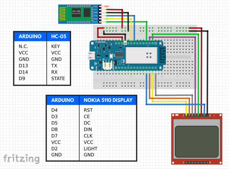 Document listing AT commands for the HC-05
Productieproces
- TinyML-taaldetector-gebaseerd op Edge Impulse &Arduino
- Arduino-gyroscoopspel met MPU-6050
- Arduino digitale dobbelstenen
- DIY 37 LED Roulette Game
- ATtiny85 Mini Arcade:Snake
- Draagbare afstandsdetector
- Arduino Audio Reactive Desk Light
- Smart Face Tracking Robot Car
- Personal Healthcare Assistant PHA
- galvaniseren met koper
- NeoMatrix Arduino Pong