


The Companion IC
Componenten en benodigdheden
 |
| × | 1 | |||
 |
| × | 1 | |||
 |
| × | 4 | |||
 |
| × | 1 | |||
 |
| × | 2 | |||
 |
| × | 3 | |||
 |
| × | 4 | |||
 |
| × | 2 | |||
 |
| × | 1 | |||
 |
| × | 1 |
Benodigde gereedschappen en machines
 |
| |||
 |
|
Over dit project
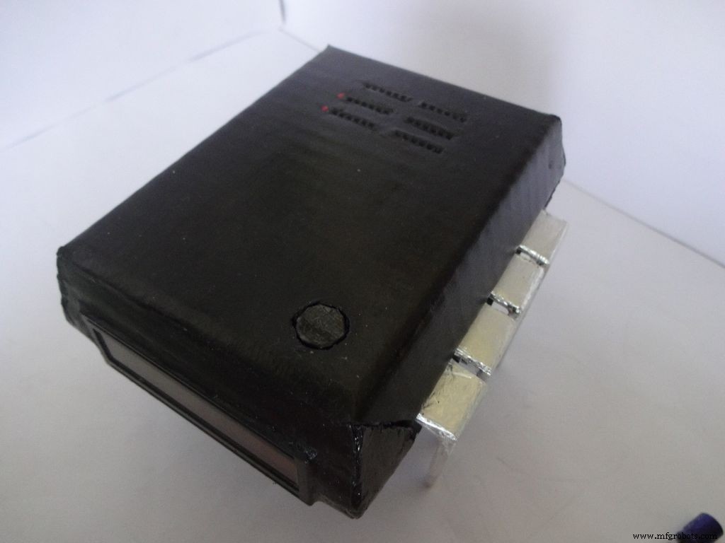

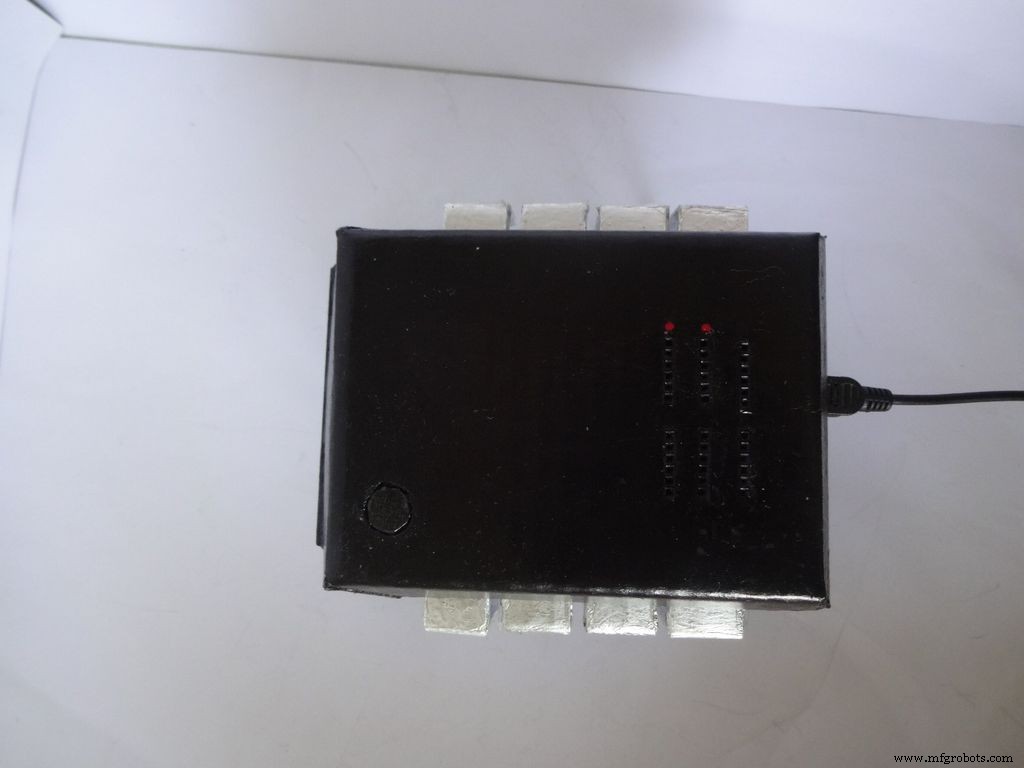
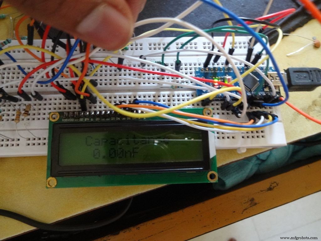
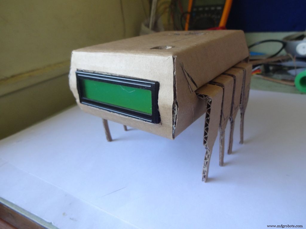
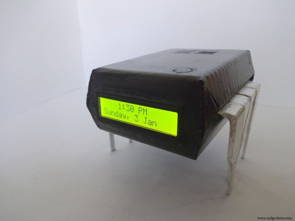
De Companion IC is een erg cool uitziende klok + ohmmeter + capaciteitsmeter + diodetester! Zet hem aan door op Pin 1 van het IC te drukken! Bewaar dit op uw werkbank voor een snelle test van componenten en controletijd. Werkt op batterijen of met USB als je een voeding in de buurt van je werkbank hebt.
Ik heb altijd al een project willen publiceren, maar heb tot nu toe nooit iets unieks gevonden om te maken! Ik kwam op het idee toen ik enkele condensatoren wilde testen om te zien of ze defect waren of niet. Ik had alleen een multimeter beschikbaar en deze had geen capaciteitsmeetfunctie. Na erover te hebben gezocht, kwam ik te weten dat de Arduino dit kan. Ik besloot er een te maken, maar het zien van de ongebruikte pinnen op de Arduino was niet erg bevredigend, dus besloot ik om ook een automatisch bereikbare Ohmmeter, snelle LED / Diode-tester en RTC-klok toe te voegen! Ik wilde ook dat het direct waarden zou meten door het onderdeel aan te sluiten en geen sondes te gebruiken. Het ontwerp moest uniek zijn dus na wat brainstormen was het IC ontwerp gemaakt!
Bewerken (07/01/2016) :Optionele continuïteitstest is toegevoegd, zie de opmerkingensectie.
In dit artikel wordt uitgebreid uitgelegd hoe ik dit heb gemaakt en hoe jij het ook zelf kunt maken. Het is beginnersvriendelijk en iedereen met 2-3 weken Arduino/Electronica-ervaring kan dit bouwen!
Het ontwerp is aanpasbaar en u kunt nieuwe functies verwijderen/toevoegen volgens uw vereisten. Ik heb de koffer gemaakt met karton, maar als je de vaardigheden hebt, kun je het met hout doen of het in 3D printen.
Ik heb geprobeerd om foto's te maken en bij te voegen bij elke stap die ik deed (veel in elke stap!). De meeste hiervan zijn meerdere keren genomen totdat ik de beste hoek/het beste licht kreeg, maar toch zijn er een paar een beetje wazig omdat het soms moeilijk is om alles met twee handen vast te houden.
Ik heb de hele code en bedrading in stukjes en stappen gebroken, precies zoals ik het heb gemaakt. De meegeleverde code is voorzien van veel commentaar en is correct ingesprongen. Als we verder gaan. we zullen stap voor stap alle code en bedrading combineren om de uiteindelijke IC te maken. Dit zou iedereen moeten helpen het duidelijk te begrijpen. Zo niet, laat het me dan weten in de reacties.
Zelfs als je besluit er geen te maken, probeer het dan op een breadboard of lees dit in ieder geval een keer door, want er moet een methode of truc zijn of iets dat je hier kunt leren en op een dag van nut voor je zal zijn (serieus, je weet nooit wanneer het klikt!)
Stap 1:Benodigde gereedschappen en componenten
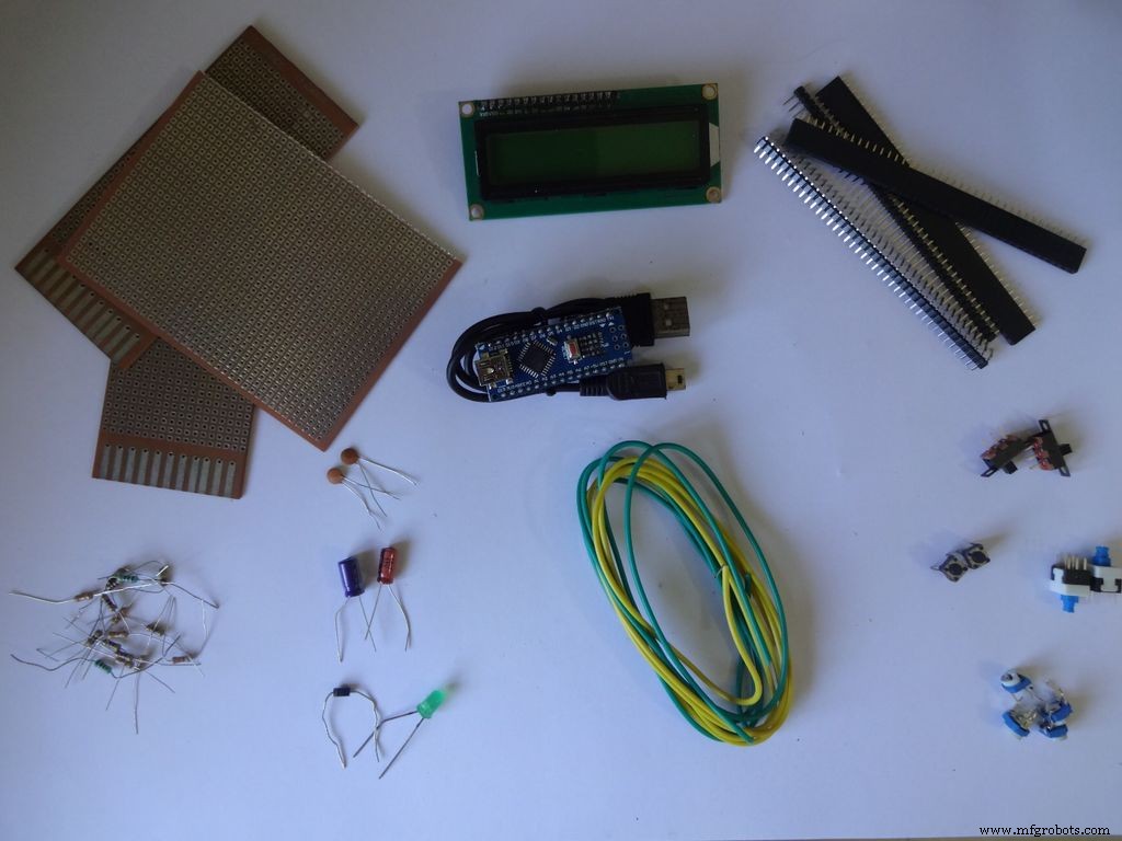

Lijst met gebruikte componenten en materialen (links opslaan alleen ter referentie):
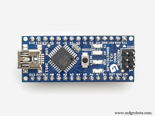
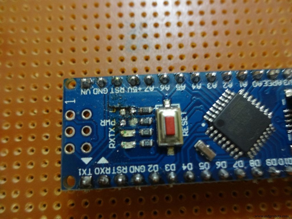
- 1x Arduino Nano V3, Ik heb een kloon met CH340G gebruikt -- ebay
- Mini-USB-kabel voor Arduino Nano -- Mini niet Micro !
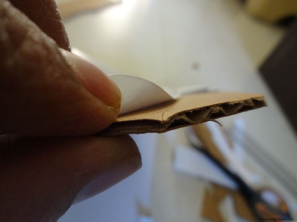
- Kartonnen -- Ik gebruikte een verpakkingsdoos, dikte ~2mm. Vraag je buurman, vrienden, ga op zoek als je er geen kunt vinden.
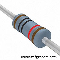
- 4x 10k ohm weerstand -- gemakkelijk verkrijgbaar
- 2x 220 ohm weerstand -- gemakkelijk verkrijgbaar
- 1x (1k, 4.7k, 47k, 100k) ohm-weerstanden -- gemakkelijk verkrijgbaar
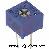
- 1x Kleine 10k ohm potentiometer, voor contrastcontrole van LCD... elk klein formaat zal werken .--ebay
- 2x Micro drukknop, voor reset- en moduswijzigingsknop, de meest voorkomende die u op een breadboard gebruikt.
- 3x kleine schuifschakelaars , voor het inschakelen van achtergrondverlichting, pinnen 0 en 1, Deze pin moet worden uitgeschakeld tijdens het gebruik van Serial -- ebay
- 1x Onderhouden/Toggle/Vergrendelende drukschakelaar, voor aan/uit-schakelaar -- ebay
- Sommige condensatoren, diodes, leds alleen om te testen, je zult ze toch ooit gebruiken.
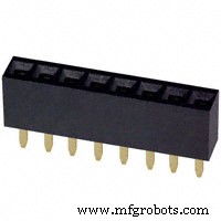
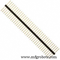
- 4x Female header pinstrip -- ebay (40 pinnen per strip)
- 2x Mannelijke header pinstrip -- ebay (40 pinnen per strip)
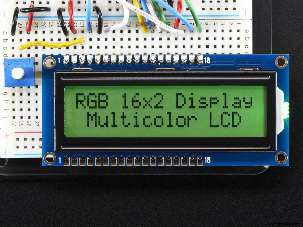
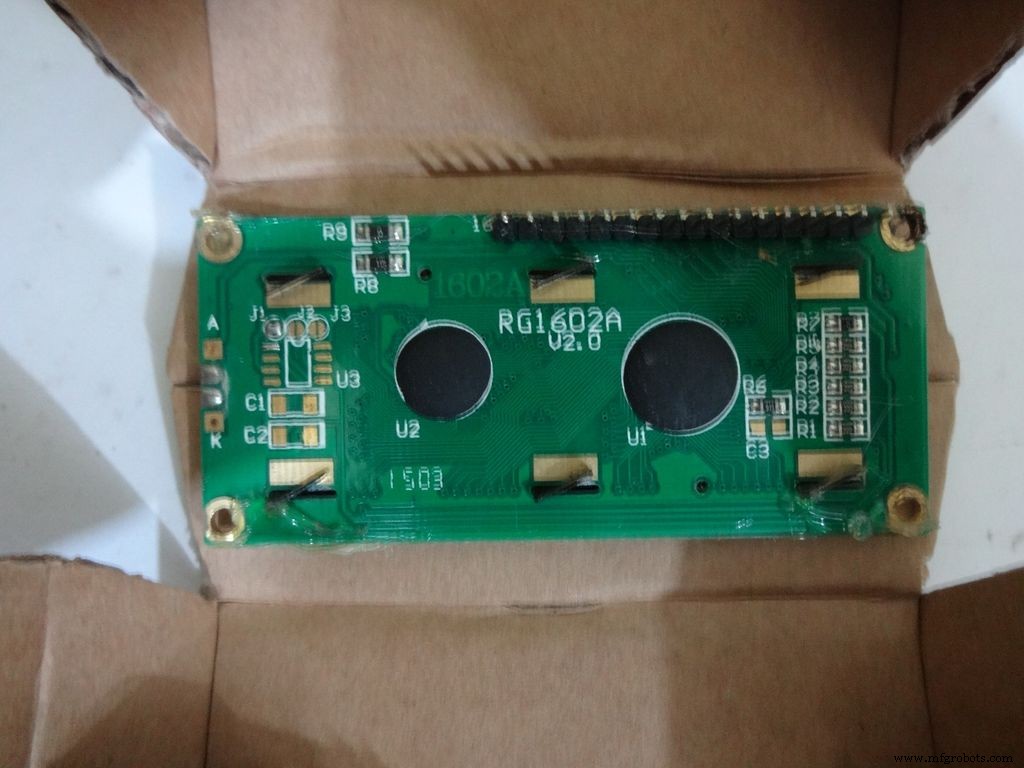
- 1x 16x2 karakter LCD -- ebay
- 1x DS3231 of DS1307 RTC-module (RTC staat voor Real Time Clock) -- Koop geen goedkope op ebay. Deze gebruiken nep-chips en zijn onnauwkeurig. Koop dit, dit of dit. Elk van deze zal werken.
- 4x AA-batterijen (of AAA. Het gebruik van AAA zal veel gemakkelijker zijn, maar de batterijcapaciteit is minder)
- 1x 4 AA (of AAA) batterijhouder , platte variant -- ebay
- Enkeldraads draad , die gebruikt worden voor breadboards, 22 gauge
- Lintkabel (of er kunnen dunne twisted pair-draden worden gebruikt) -- ebay
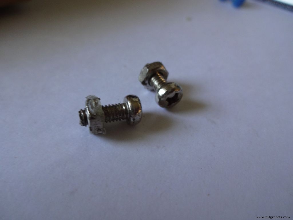
- 2x Kleine moer en bout -- Ik gebruikte die van mijn oude Meccano-set (bouten zijn 1,3 cm lang)
- Zwarte acrylverf en penselen
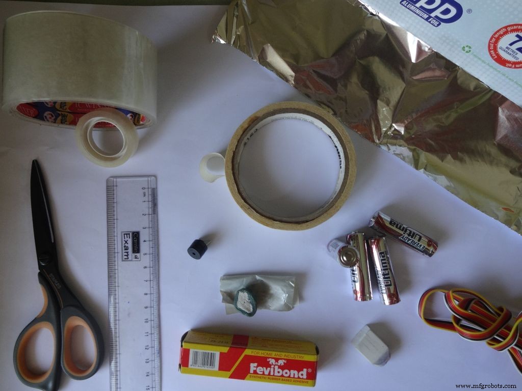
Benodigde hulpmiddelen:
- Soldeerbout
- Soldeer
- Desoldeerlont/vlecht (voor als je het verknoeit!)
- Lijmpistool
- Afplakband
- Cellotape, transparant
- Draadstripper, tang
- Scherpe dozensnijder
- Scherpe schaar
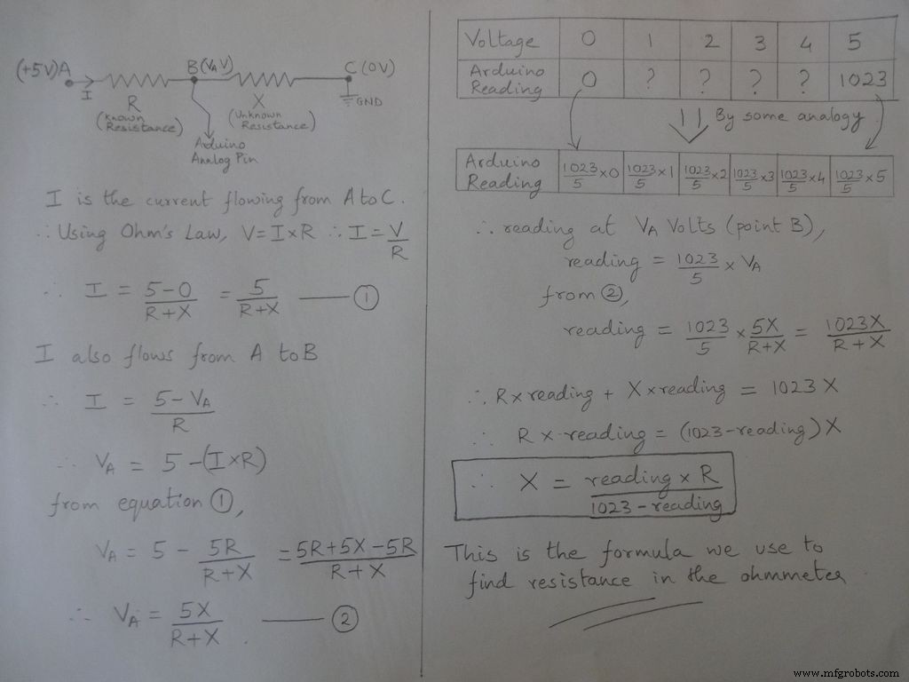
Stap 2:Ohmmeter - Concept
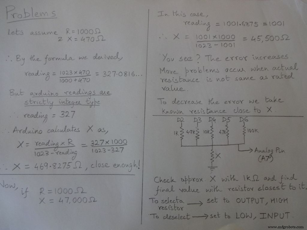
Het basisidee van het meten van weerstand komt van de spanningsdeler.
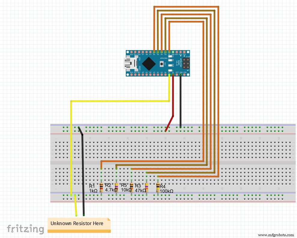
Weerstandswaarden kunnen worden gewijzigd, verander de waarden van r1, r2, enz. Stel ook de bereiken (voor automatisch bereik) dienovereenkomstig in. Zie onderstaande code, download deze uit de bestanden aan de uiteinden en test de ohmmeter op een breadboard
Als je Nano voor de eerste keer instelt, kan de CH340G-driver hiervoor hier worden gedownload, werkt met Windows 7, 8, 8.1 en 10. Mac-gebruikers checken hier.
Selecteer "Arduino Nano" in het bordmenu en de juiste COM-poort. Uploaden!
Code
//Analoge pin gebruikt om resistanceint te vinden Apin=7;//waarden van r1 tot r5float r1=1000;float r2=4700;float r3=10000;float r4=47000;float r5=100000;/ /pins van r1 tot r5int r1_pin=2;int r2_pin=3;int r3_pin=4;int r4_pin=5;int r5_pin=6;float reading=0; // lees van analoge pin en sla hier drijvend op R =0; // bereken onbekend en sla hereString finalR op; //definitieve waarde die samen met unitsint caseno moet worden weergegeven; //voor debuggen, slaat het casenummer op // we verdelen het hele bereik in cases en kennen elk een nummer toe, in totaal 5 cases // case1:minder dan 2850 // case2:2850 tot 7350 // case3:7350 tot 28500 // case4 :28500 tot 73500 // case5 :more than 73500#include // nodig voor het converteren van float naar string, heeft de String(float,n) functie. Hieronder uitgelegd.void setup() {Serial.begin(9600);}void loop() { // eerst vinden we onbekende weerstand met 1kOhm-weerstand // Schakel daarom R2, R3, R4 en R5 digitalWrite (r2_pin, LOW) uit; // draai elke pin naar LOW voordat je deze instelt als INPUT pinMode (r2_pin, INPUT); // door het INPUT te draaien wanneer het HIGH is, wordt de interne pullup-weerstand digitalWrite (r3_pin, LOW) ingeschakeld; pinMode(r3_pin, INPUT); digitalWrite(r4_pin, LAAG); pinMode(r4_pin, INPUT); digitalWrite(r5_pin, LAAG); pinMode(r5_pin, INPUT); pinMode (r1_pin, UITGANG); digitalWrite(r1_pin, HOOG); // lees en bereken weerstandswaarde =analogRead (Apin); R=(lezing*r1)/(1023-lezing); // als waarde <2850, finalR =waarde (met 1 kOhm) als (R <2850) {caseno =1; if(R<1000){ //if waarde kleiner dan 1000 gebruik "Ohm" niet "kOhm" finalR =String (R,2) + "Ohm"; //String(float,n) Float omzetten in string met n cijfers achter decimaal // voeg "Ohm" toe na waarde aan de string, '+' voegt hier twee strings samen } else{ //use "kOhm R=R/1000; finalR =String(R,2) + "kOhm"; } } //if waarde tussen 2850 en 7350, gebruik waarde verkregen door 4.7kOhm else if(R>=2850 &&R<7350){ caseno=2; digitalWrite(r1_pin , LOW); //Alleen 4,7kOhm inschakelen pinMode(r1_pin, INPUT); digitalWrite(r3_pin, LOW); pinMode(r3_pin, INPUT); digitalWrite(r4_pin, LOW); pinMode(r4_pin, INPUT); digitalWrite(r5_pin, LOW ); pinMode(r5_pin, INPUT); pinMode(r2_pin, OUTPUT); digitalWrite(r2_pin, HIGH); reading=analogRead(Apin); R=(reading*r2)/(1023-reading)/1000; finalR =String( R,2) + "kOhm";} //if waarde tussen 7350 en 28500, gebruik waarde verkregen door 10kOhm else if(R>=7350 &&R<28500){ caseno=3; digitalWrite(r1_pin, LOW); pinMode( r1_pin, INPUT); digitalWrite(r2_pin, LOW); pinMode(r2_pin, INPUT); digitalWrite(r4_pin, LOW); pinMode(r4_pin, INPUT); digitalWrite(r5_pin, LOW); pinMode(r5_pin, INPUT); pinM ode(r3_pin, UITGANG); digitalWrite(r3_pin, HOOG); lezen =analoog lezen (Apin); R=(lezing*r3)/(1023-lezing)/1000; finalR=String(R,2) + "kOhm"; } //if waarde tussen 28500 en 73500, gebruik waarde verkregen door 47kOhm else if(R>=28500 &&R<73500){ caseno=4; digitalWrite(r1_pin, LAAG); pinMode(r1_pin, INPUT); digitalWrite(r2_pin, LAAG); pinMode(r2_pin, INPUT); digitalWrite(r3_pin, LAAG); pinMode(r3_pin, INPUT); digitalWrite(r5_pin, LAAG); pinMode(r5_pin, INPUT); pinMode (r4_pin, UITGANG); digitalWrite(r4_pin, HOOG); lezen =analoog lezen (Apin); R=(lezing*r4)/(1023-lezing)/1000; finalR =String(R,2) + "kOhm"; } // als de waarde hoger is dan 73500, gebruik dan de waarde verkregen door 100 kOhm else if(R>=73500){ caseno=5; digitalWrite(r1_pin, LAAG); pinMode(r1_pin, INPUT); digitalWrite(r2_pin, LAAG); pinMode(r2_pin, INPUT); digitalWrite(r3_pin, LAAG); pinMode(r3_pin, INPUT); digitalWrite(r4_pin, LAAG); pinMode(r4_pin, INPUT); pinMode(r5_pin, UITGANG); digitalWrite(r5_pin, HOOG); lezen =analoog lezen (Apin); R=(lezing*r5)/(1023-lezing)/1000; finalR =String(R,2) + "kOhm"; } Serieel.println(finalR); //afdrukken van de laatste string met eenheden Serial.println(" "); vertraging(1000);}
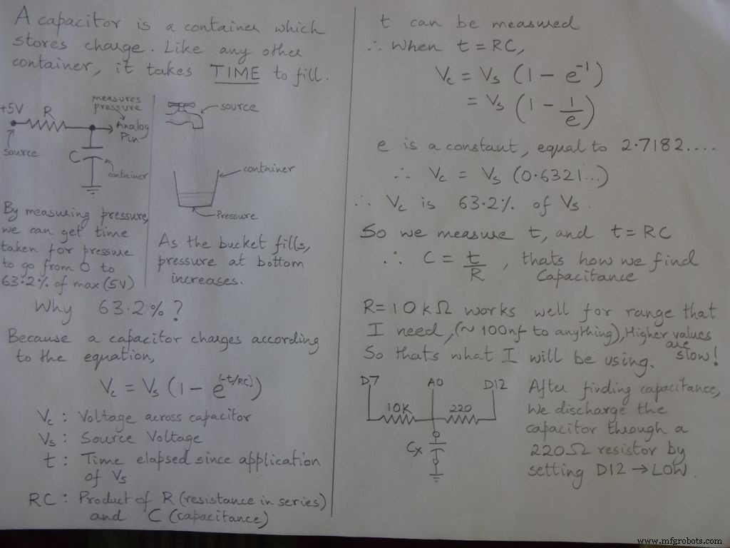
Stap 3:Capaciteitsmeter - Concept

Code
/* RCTiming_capacitance_meter * codeconcept overgenomen van Paul Badger 2008 * * De constante spanning van de condensator is gedefinieerd als 63,2% van de laadspanning. * d.w.z. een condensator is gevuld tot 63,2% van zijn totale capaciteit in 1 tijdconstante */ int analogPin=0; // analoge pin voor het meten van condensatorspanning int chargePin =7; // pin om de condensator op te laden - aangesloten op het ene uiteinde van de laadweerstand int lossingPin=12; // pin om de condensator te ontladen, dezelfde die wordt gebruikt voor diodetest (chechPin1) vlotterweerstand Waarde =10000.0; // We gebruiken 10kOhm weerstand unsigned long startTime; niet-ondertekende lange verstreken tijd; drijvende microFarads; // variabele met drijvende komma om de precisie te behouden, berekeningen te laten zweven nanoFarads; void setup () {pinMode (chargePin, OUTPUT); // stel chargePin in om digitalWrite uit te voeren (chargePin, LOW); Serieel.begin(9600); // initialiseer seriële verzending voor foutopsporing} void loop () {digitalWrite (chargePin, HIGH); // zet chargePin HIGH en condensator opladen startTime =millis (); while(analogRead(analogPin) <648){ // 647 is 63,2% van 1023, wat overeenkomt met volledige spanning} elapsedTime=millis() - startTime; // converteer milliseconden naar seconden (10 ^ -3) en Farads naar microFarads (10 ^ 6), netto 10 ^ 3 (1000) microFarads =((float)elapsedTime / resistanceValue) * 1000; // (float) converteert "unsigned long" verstreken tijd naar float Serial.print(elapsedTime); // druk de waarde af naar seriële poort Serial.print ("mS "); // afdrukeenheden if (microFarads> 1){ Serial.print ((long)microFarads); // druk de waarde af naar seriële poort Serial.println ("microFarads"); // print units } else { // als de waarde kleiner is dan één microFarad, converteer dan naar nanoFarads (10^-9 Farad). nanoFarads =microFarads * 1000,0; // vermenigvuldig met 1000 om te converteren naar nanoFarads (10^-9 Farads) Serial.print((long)nanoFarads); // druk de waarde af naar seriële poort Serial.println ("nanoFarads"); // print units } /* ontlaad de condensator */ digitalWrite(chargePin, LOW); // zet de laadpin op LOW pinMode (dischargePin, OUTPUT); // stel de ontladingspin in om digitalWrite uit te voeren (dischargePin, LOW); // zet de ontladingspin LOW while (analogRead (analogPin)> 0) {// wacht tot de condensator volledig is ontladen} pinMode (dischargePin, INPUT); // zet de ontladingspin terug op input}
Stap 4:Diodetest
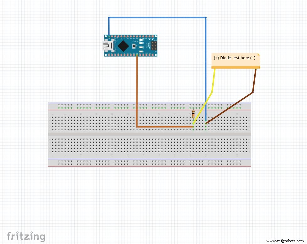
De analoge pin wordt opgetrokken tot 5V met de 10k Ohm-weerstand. Dus analoge pin leest 1023 als er niets is aangesloten. D12 is ingesteld op OUTPUT , LAAG .
Wanneer een diode voorwaarts is voorgespannen tussen analoge pin (5V ) en D12 (GND ), analoge pin leest 100-400 .
Wanneer het omgekeerd voorgespannen is, vloeit er praktisch een zeer kleine stroom en analoge pin leest 900-1023 .
Op deze manier kunnen we eenvoudig de p- en n-zijde van een diode achterhalen. Dit kan worden gebruikt voor het snel controleren van LED's en diodes.
Code
String state ="null";int checkPin1 =12;int checkPin2 =6;void setup() { Serial.begin(9600);}void loop() {pinMode(checkPin1, OUTPUT); digitalWrite (checkPin1, LAAG); //pin 11 is ingesteld op laag//analoge lezen wordt normaal gesproken omhoog getrokken door de 10k-weerstand, dus de nulwaarde is 1023// In voorwaartse bias wordt de analoge pin verbonden met checkPin1, die LAAG is. Dus als we minder dan 1023// lezen, stroomt er praktisch ook een kleine stroom in omgekeerde voorspanning, dus we nemen 700 om te differentiëren if(analogRead(checkPin2)<700){ state="forward"; } Serieel.println(staat); Serial.println(analogRead(checkPin2)); staat ="null"; vertraging(500);}
Stap 5:De realtimeklok (RTC)
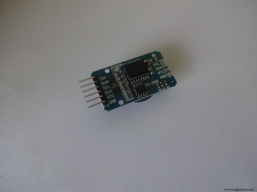
De RTC houdt informatie over seconden, minuten, uren, dag, datum, maand en jaar bij. Het blijft tellen, zelfs als de externe voeding is verwijderd, dankzij de kleine knoopcel erin. De datum aan het einde van de maand wordt automatisch aangepast voor maanden met minder dan 31 dagen, inclusief correcties voor schrikkeljaar.
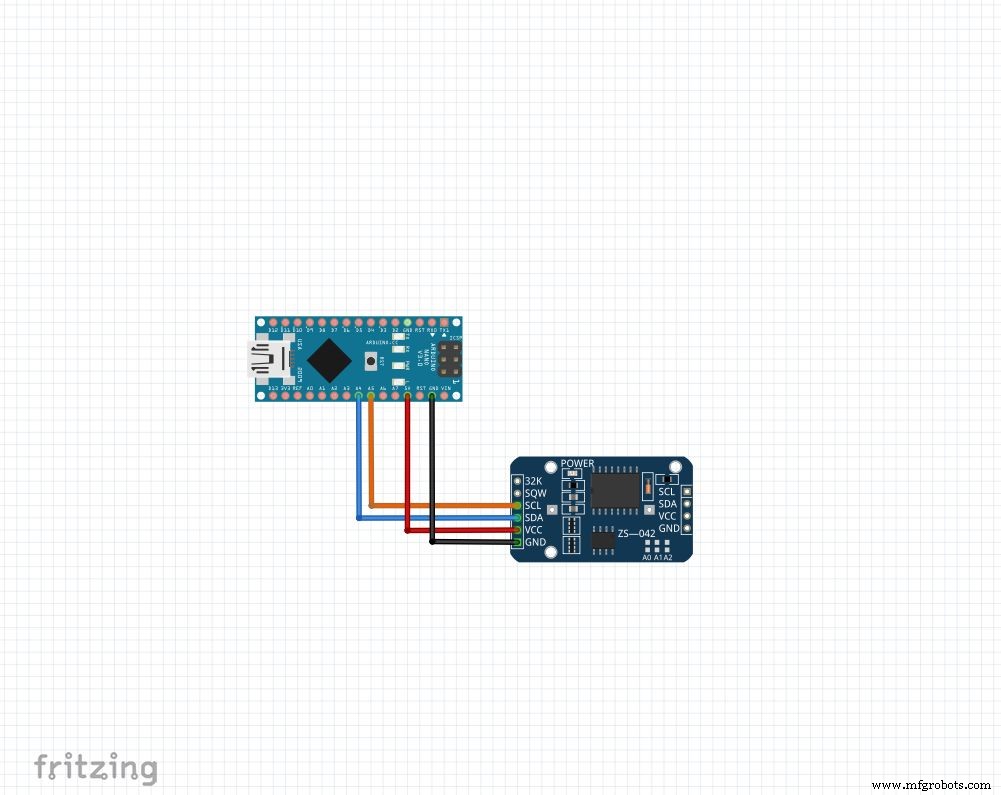
Welke module je ook hebt, we gebruiken 4 pinnen:Vcc , GND ,SDA en SCL . De SDA en SCL pinnen op de arduino nano en uno zijn A4 en A5 respectievelijk. Voor andere arduino's google het op!
We zullen de "RTClib"-bibliotheek gebruiken, wat het instellen en openen van tijd supereenvoudig maakt! De bibliotheek kan hier worden gedownload (Klik op "Download ZIP" en pak de "RTClib-master" uit in uw Arduino-bibliothekenmap. Meer over het installeren van bibliotheken.)
Om de tijd in te stellen, download de "RTC_set_time.ino" die bij deze stap is gevoegd en verwijder de opmerkingen bij de regels,
rtc.adjust(DateTime(F(__DATE__), F(__TIME__)));
Als u de tijd wilt gebruiken die op uw computer is ingesteld tijdens het compileren. Of
rtc.adjust(DateTime(2014, 1, 21, 3, 0, 0)); //jaar, maand, datum, uur, minuut, seconden
Om een aangepaste tijd in te stellen.
Sluit aan zoals getoond en upload. Open Serie monitor op 9600 baud om de huidige tijd te zien. Controleer na enkele uren nog eens hoe de RTC de achterstand inhaalt.
Zorg ervoor dat je deze regels aanbeveelt en upload opnieuw nadat je de tijd eenmaal hebt ingesteld. Anders blijf je het elke keer resetten als Arduino reset!
Code
// Datum- en tijdfuncties met behulp van een DS1307 RTC verbonden via I2C en Wire lib#include #include RTC_DS1307 rtc;//creëren van "rtc" object van RTC_DS1307, objecten worden gebruikt om toegang te krijgen tot functies //meer over objecten en klassen:https://www.youtube.com/watch?v=ABRP_5RYhqUchar daysOfTheWeek[7][12] ={"Sunday", "Monday", "Tuesday", " woensdag", "donderdag", "vrijdag", "zaterdag"};void setup () { Serial.begin(9600); rtc.begin(); // volgende regel stelt de RTC in op de datum en tijd waarop deze schets is gecompileerd // rtc.adjust(DateTime(F(__DATE__), F(__TIME__))); // Deze regel stelt de RTC in met een expliciete datum en tijd, bijvoorbeeld om // 21 januari 2014 om 03:00 uur in te stellen die u zou noemen:// rtc.adjust(DateTime(2014, 1, 21, 3, 0, 0) );}void loop () { DateTime now =rtc.now(); Serial.print(nu.jaar()); Serieel.print('/'); Serial.print(nu.maand()); Serieel.print('/'); Serial.print(nu.day()); Serial.print(" ("); Serial.print(daysOfTheWeek[now.dayOfTheWeek()]); Serial.print(") "); Serial.print(nu.uur()); Serieel.print(':'); Serial.print(nu.minute()); Serieel.print(':'); Serial.print(now.second()); Serieel.println(); Serieel.println(); vertraging(1000);}
Stap 6:definitieve installatie
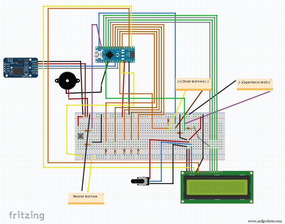
Dus dat is het laatste circuit na het combineren van alle elementen. De hoofdcode en het fritzing-bestand zijn aan het einde bijgevoegd.
Download fritzing van fritzing.org als je dat nog niet hebt gedaan.
Pak het bestand Main_code.rar uit en open Main_file_rtc.ino. Ik heb alle variabele declaraties opgenomen in een aparte definations.h header-bestand, wordt het automatisch toegevoegd wanneer u de hoofdcode opent.
Van de verschillende onderdelen zijn functies gemaakt: Clock() , findResistance() , findCapcitance() en diodeTest() . Deze zijn in aparte tabbladen geschreven, waardoor het lezen gemakkelijk is en wijzigingen eenvoudig door te voeren zijn. Het hoofdbestand controleert alleen de status van de "modusknop" en roept de juiste functies aan.
Andere details worden goed uitgelegd in de code zelf.
Na een testrun op een breadboard zijn we klaar om de IC te gaan maken!
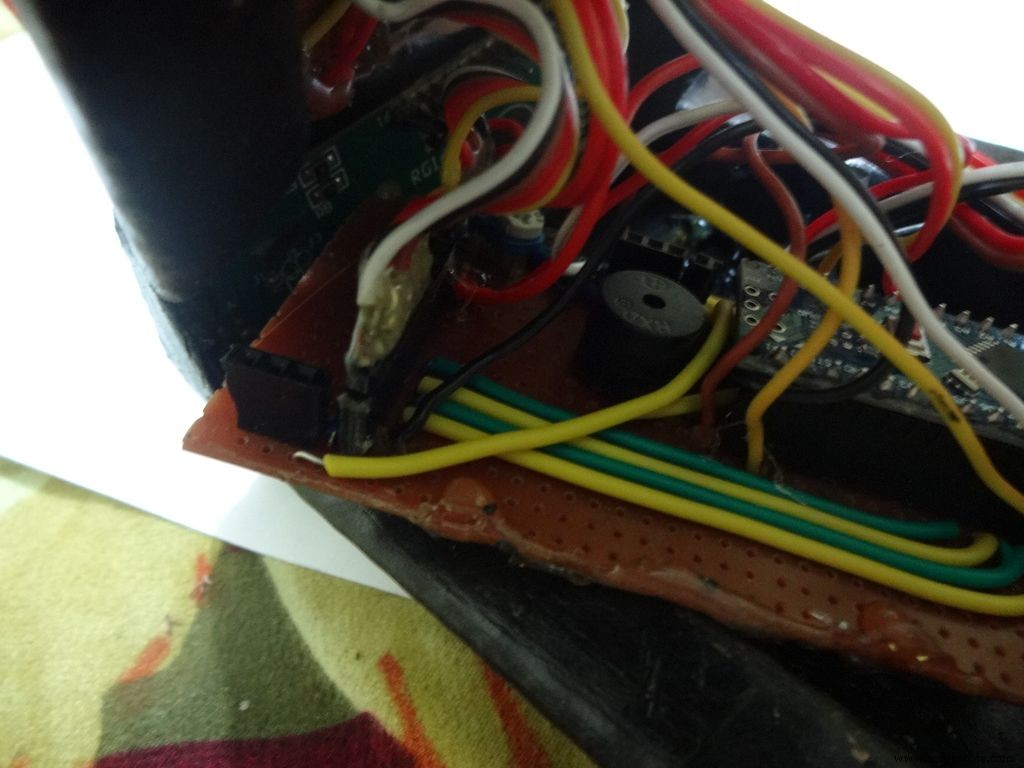
Opmerking:zoemer, indien nog niet gebruikt, kan indien nodig worden gebruikt, bijvoorbeeld een continuïteitsfunctie.
Stap 7:De schakelaars voorbereiden
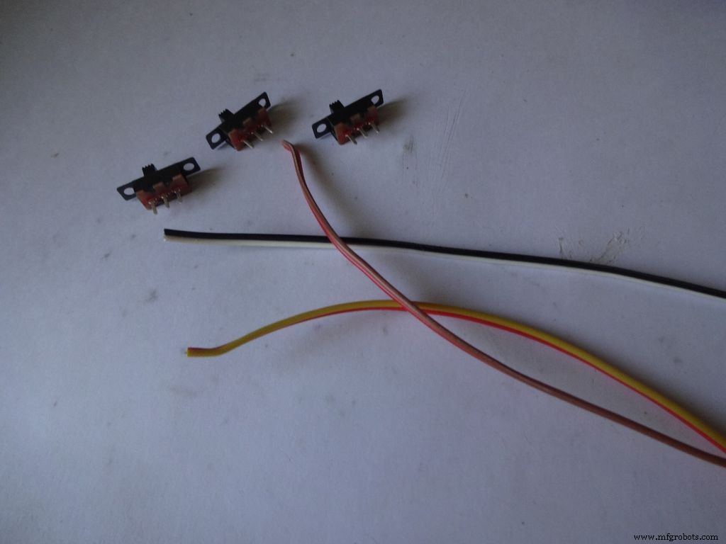
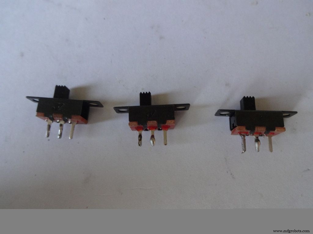


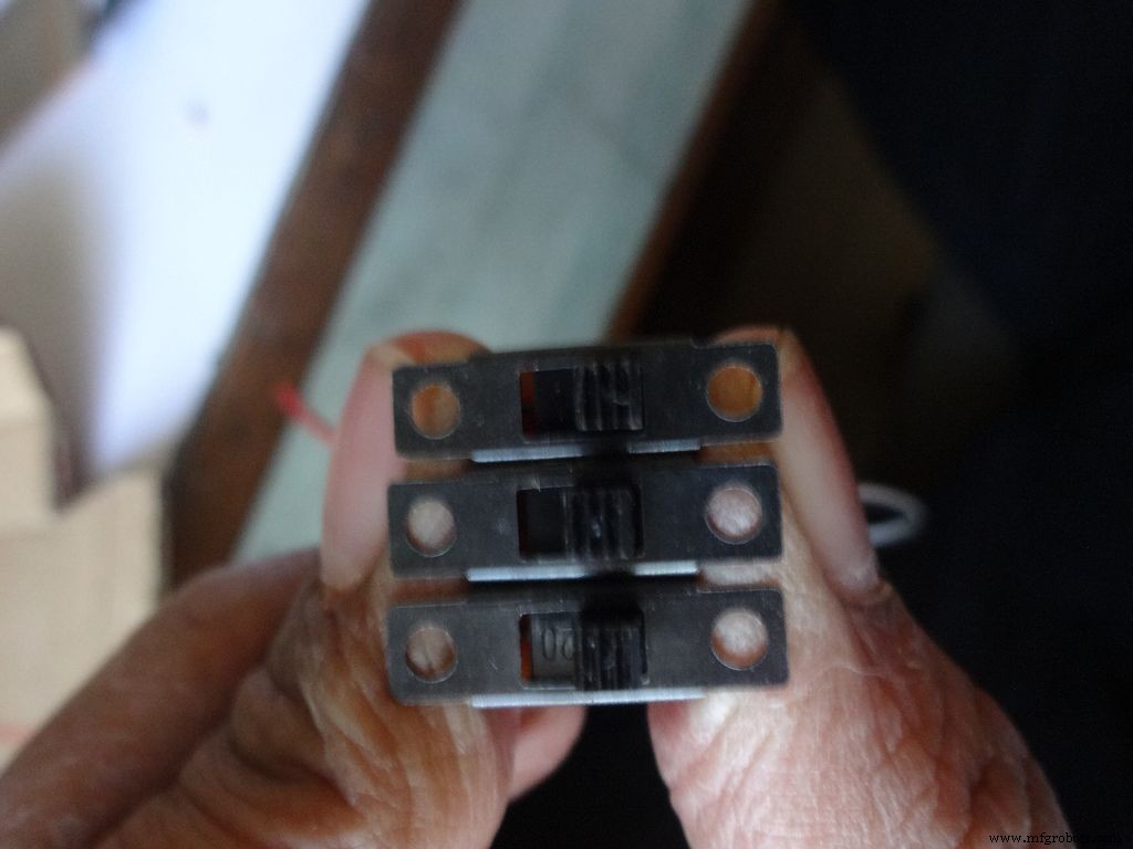
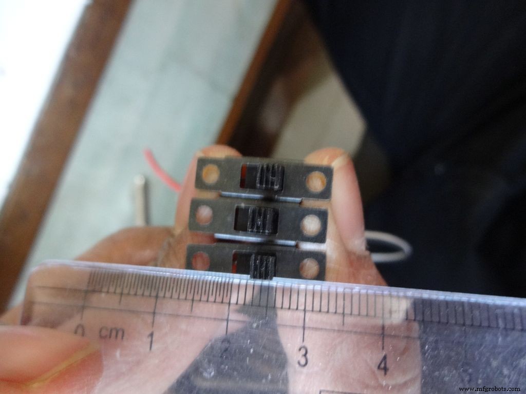
Neem de 3 schuifschakelaars samen met 3 paar draad, ongeveer 10 cm lang. Ik heb hiervoor de lintkabel gesplitst.
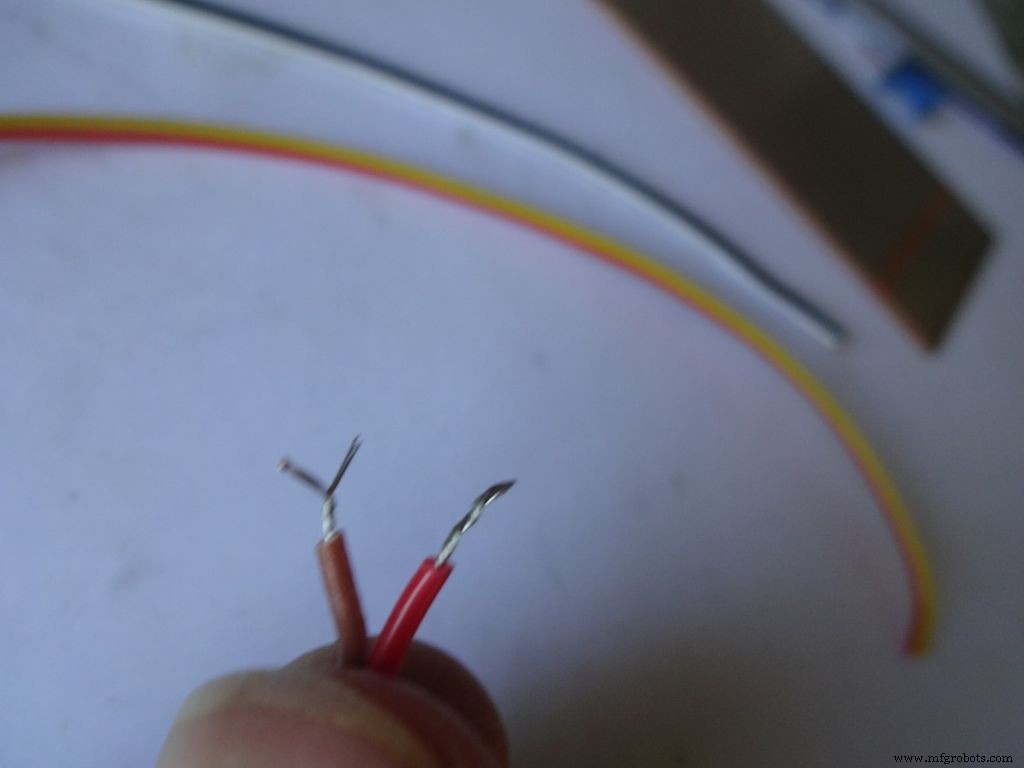
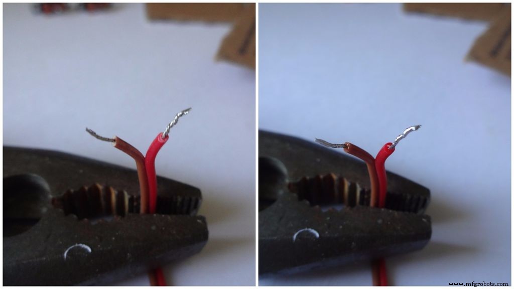
Strip een klein deel van de isolatie (niet meer dan 5 mm) en draai de strengen.
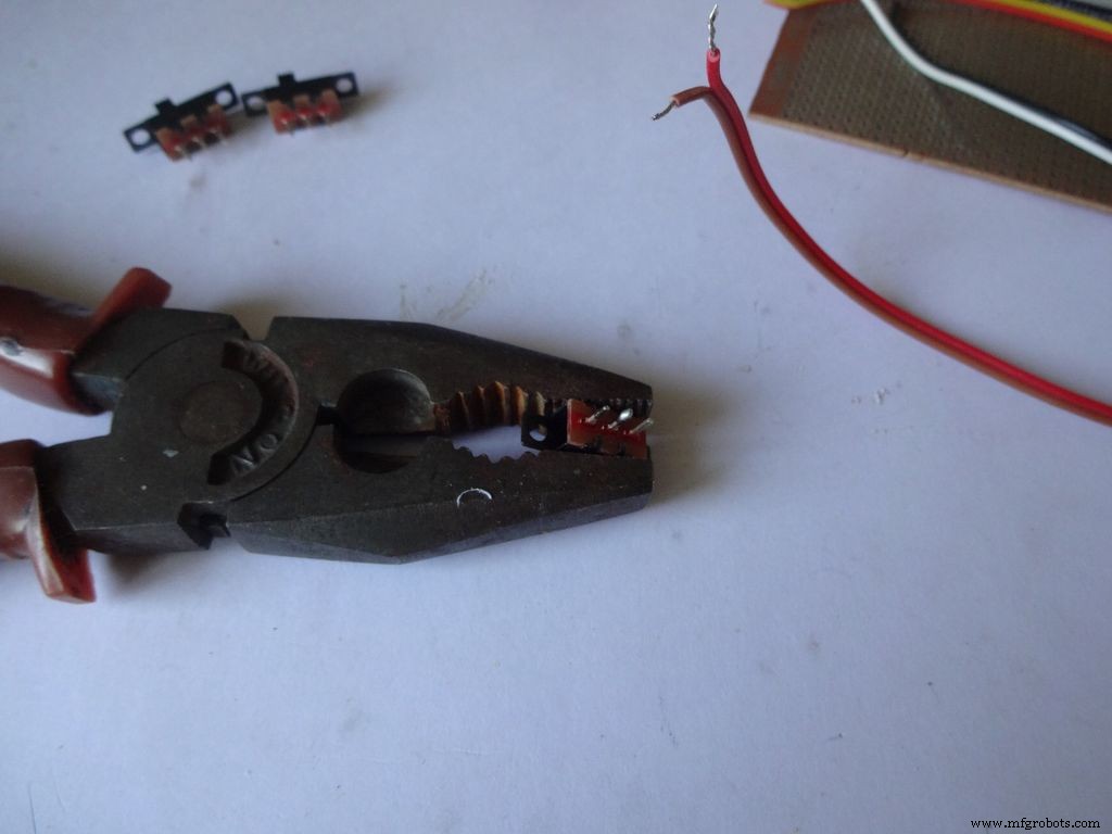
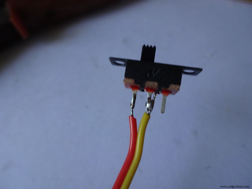
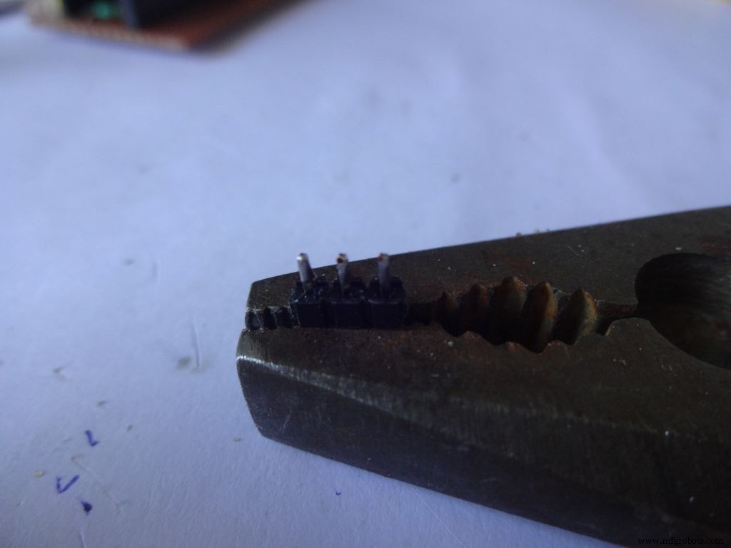
Breng wat soldeer aan op 2 aangrenzende pinnen van elk van de schakelaars. Gebruik iets om het op zijn plaats te houden terwijl je soldeert, ik gebruikte een zware tang.
Als je nog niet eerder hebt gesoldeerd, is dit een goed moment om te beginnen. YouTube heeft tonnen video's over hoe je goed soldeert. Lessen van PACE zijn zeer informatief, kijk er alstublieft naar.
Vervolgens moeten we de draden 'vertinnen'. Raak met de punt van de soldeerbout de te vertinnen draad aan. Breng een klein beetje soldeer aan tussen de punt en de draad, hierdoor ontstaat een brug die warmte van de punt naar de draad geleidt. Dan breng je soldeer rechtstreeks op de draad aan, aan de andere kant van de soldeerboutpunt . Verwijder het soldeer. Verwijder de punt. Een video hierover.
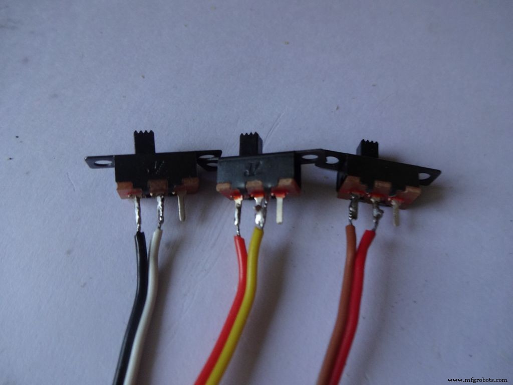
Houd daarna de schakelaar op zijn plaats, breng een van de vertinde draad naar de pin en laat het soldeer terugvloeien door de soldeerbout aan te raken. Doe hetzelfde met de tweede draad. Merk op dat ik de donkergekleurde draden aan een kant van de schakelaars heb gelegd.
Herhaal nu de procedure en bevestig twee draden aan een drukknop (dit wordt de resetknop). Zorg ervoor dat u geen draden aansluit op de normaal aangesloten uiteinden van de knop.
Stap 8:De behuizing maken - de lay-out uitsnijden
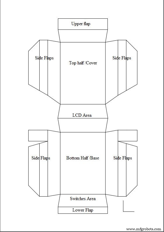
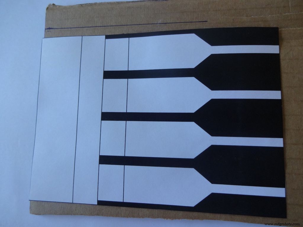
Download "Layout_Final_A3.pdf" of ""Layout_Final_ANSI_B.pdf", op basis van het beschikbare papierformaat in uw regio. toegevoegd aan het einde.
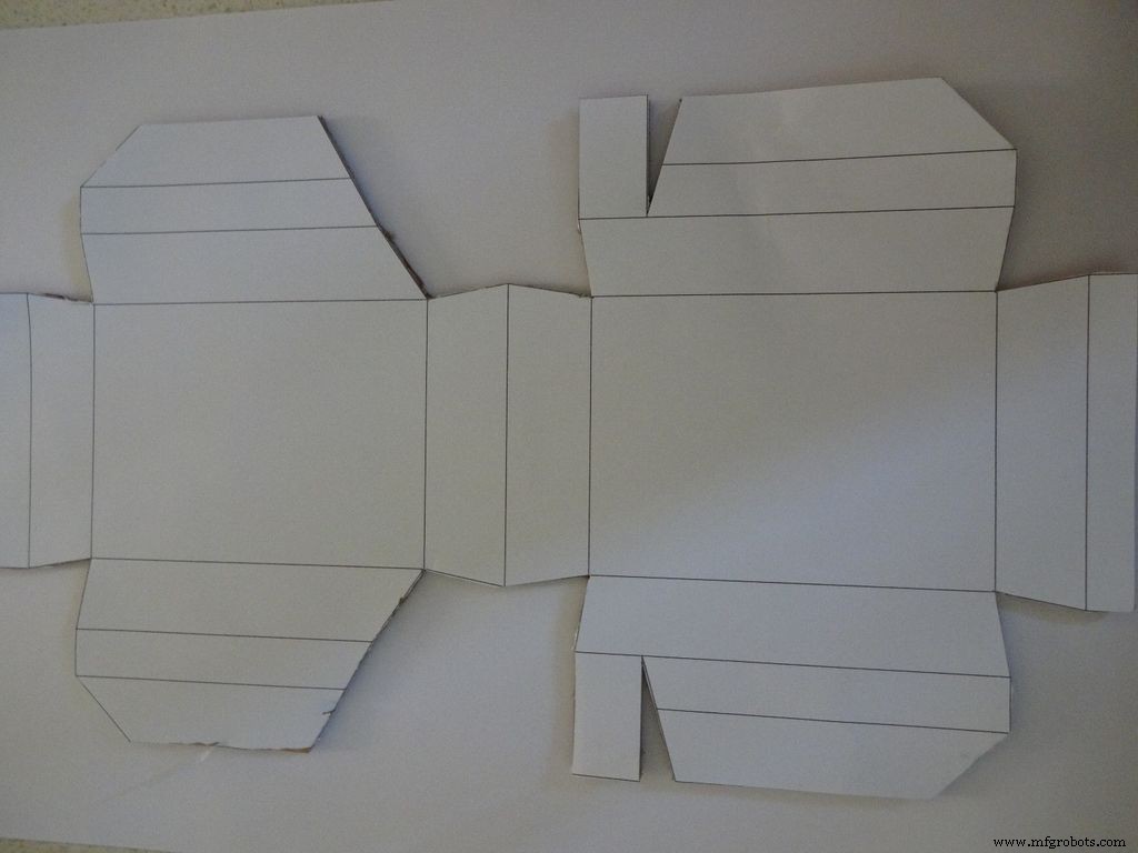
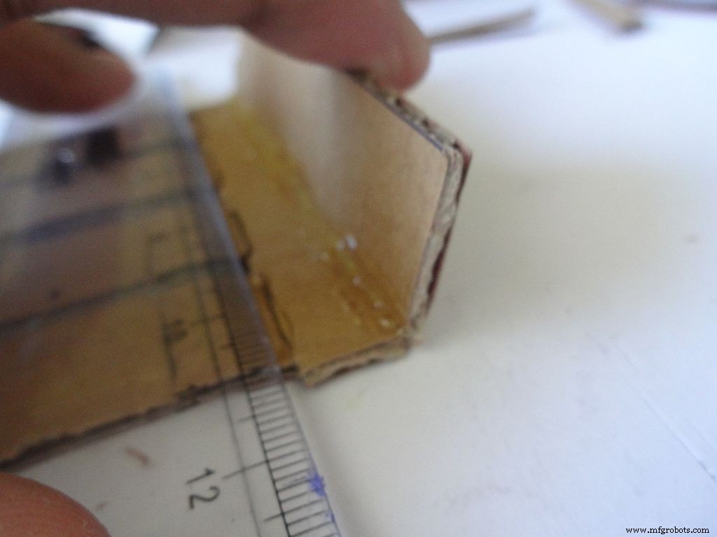
Druk het af op A3-papier (29,7 x 42,0 cm of 11,69 x 16,53 inch) of het Amerikaanse alternatief ANSI B (11 x 17 inch of 279 x 432 mm). Zorg ervoor dat u tijdens het afdrukken het juiste papierformaat en de juiste richting selecteert en de optie "Werkelijk formaat" selecteert. Controleer of de afdruk nauwkeurig is door de kleine rechte hoek in de rechterbenedenhoek te meten, deze moet 2 cm x 2 cm zijn.
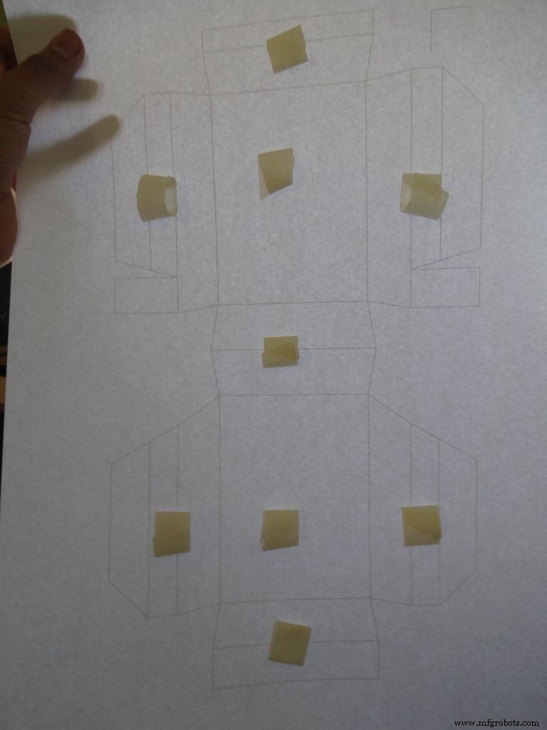
Knip een stuk karton ongeveer meer uit dan de lay-out. Scheur een klein stukje tape af, vorm een 'double side sticky' rol en bevestig deze op de aangegeven plaatsen. Plak het vel vervolgens op het karton.
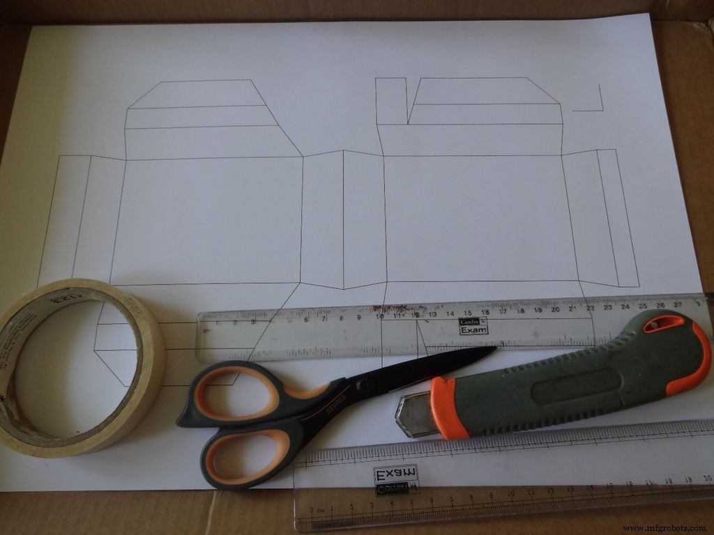
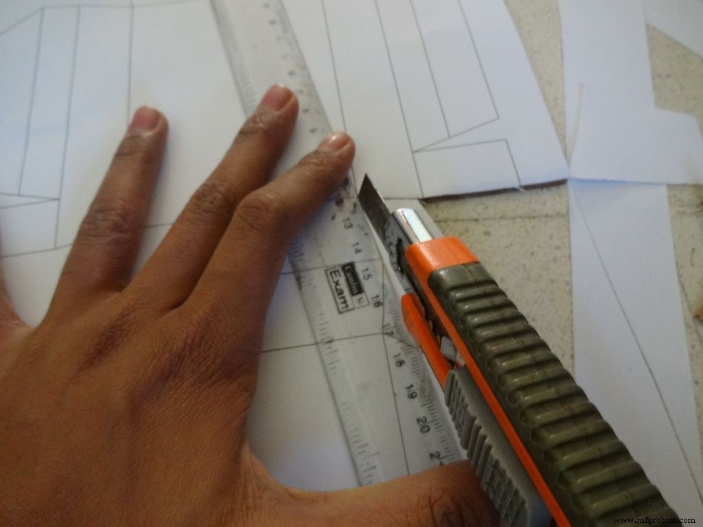
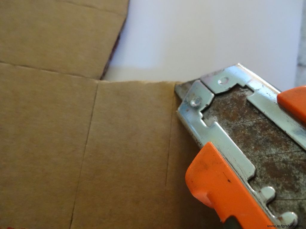
Gebruik een scherpe schaar of een stanleymes met een liniaal om de buitenste rand van de behuizingslay-out te snijden. Ik vond kokers veel beter dan scharen. De meeste frezen hebben messen die in fasen kunnen worden gebroken om een frisse en scherpe punt te krijgen, dus dat wordt aanbevolen. Houd een ander stuk karton of hout onder het deel dat u snijdt, dit helpt om schonere sneden te krijgen.
Ook het niet goed op de lijn houden van de liniaal tijdens het snijden is een veel voorkomende fout. Doe dit niet overhaast.
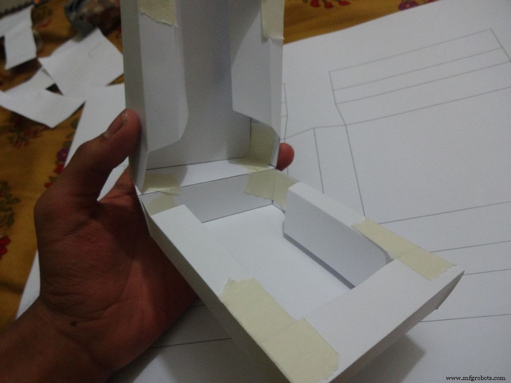
Stap 9:Het maken van de zaak - vouwen en vouwen
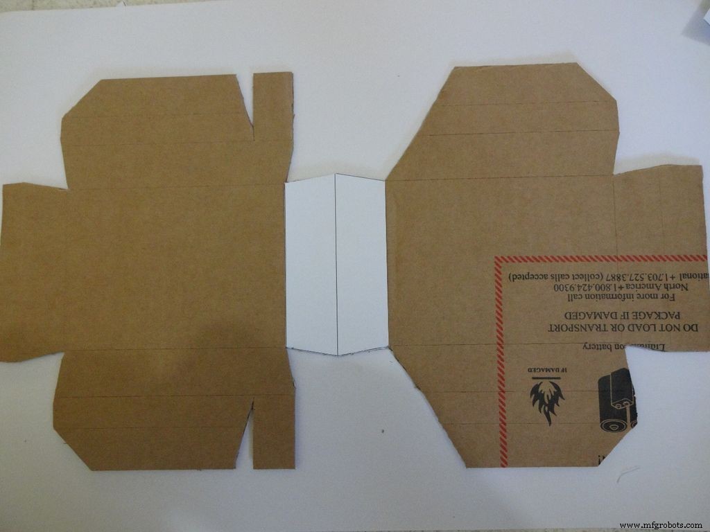
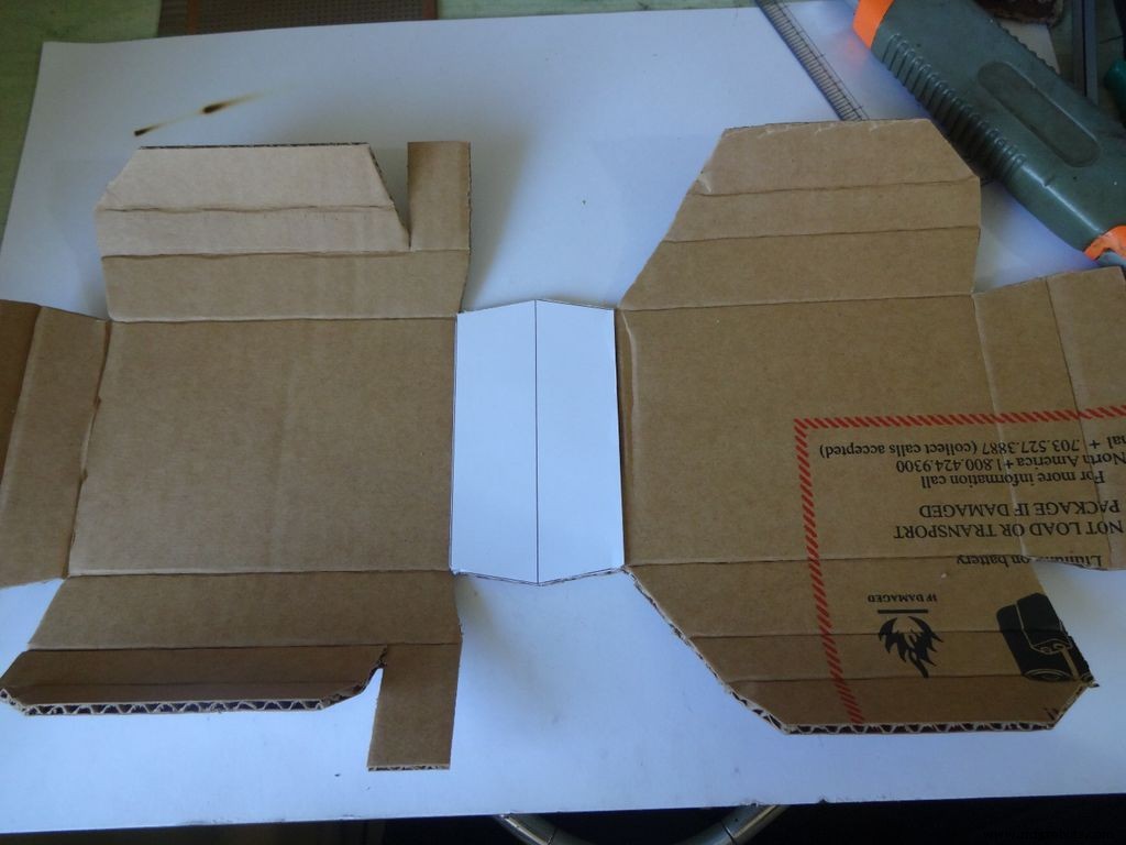


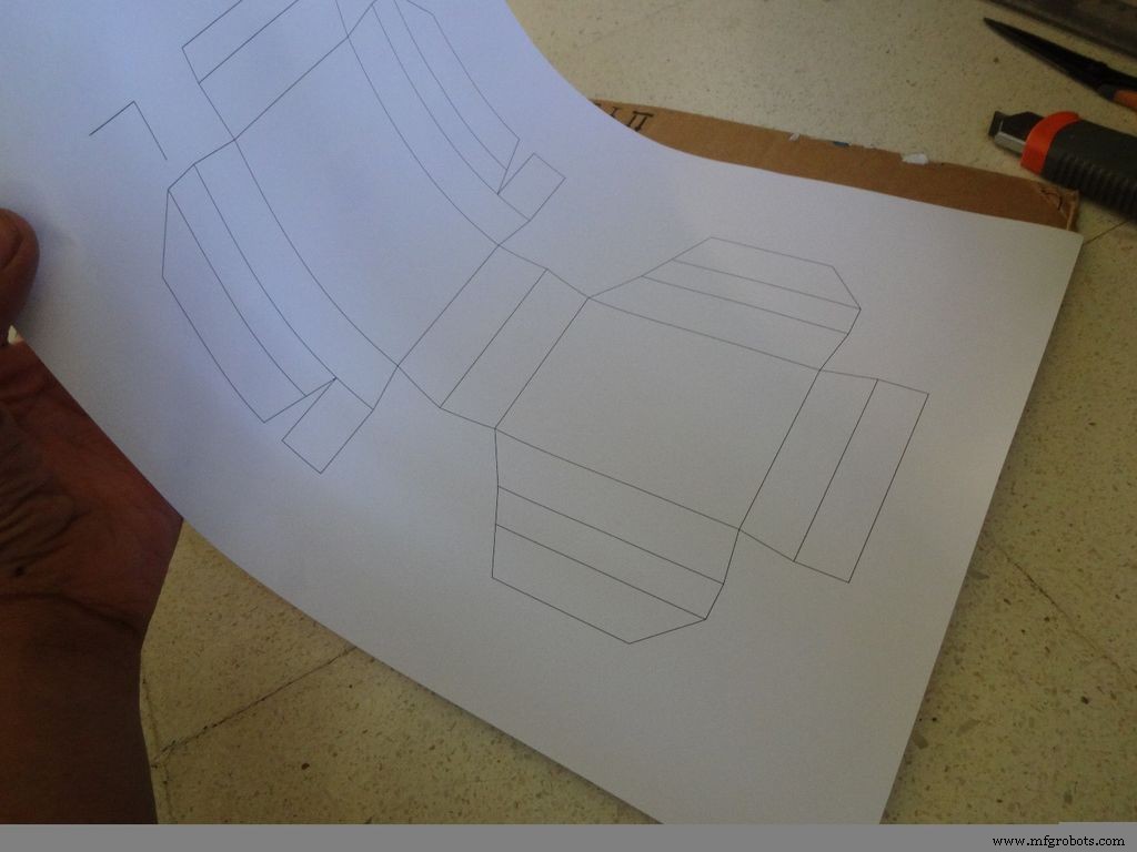
Gebruik de snijplotter met de schaal en maak voorzichtig plooien langs alle vouwlijnen, behalve de middelste lijn in het LCD-gebied. Buig en vouw alle opvouwbare delen en corrigeer eventuele onvolledige vouwen.
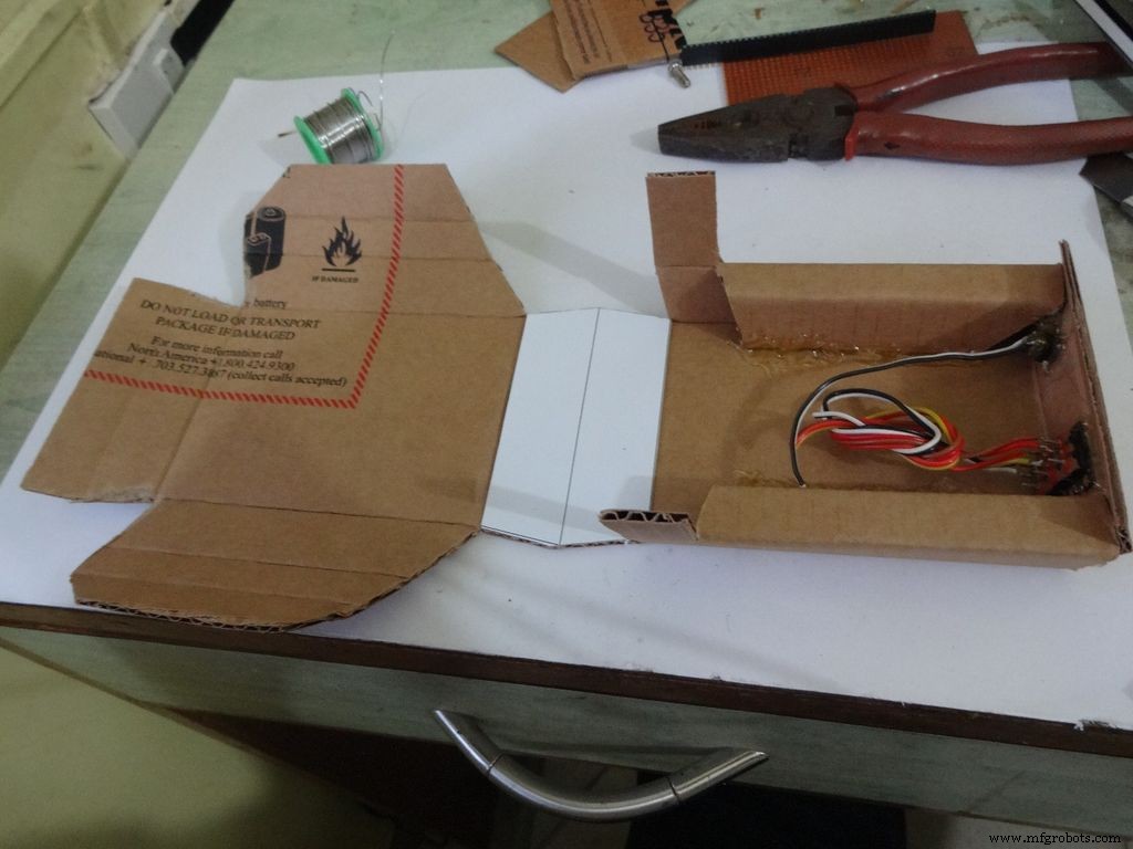
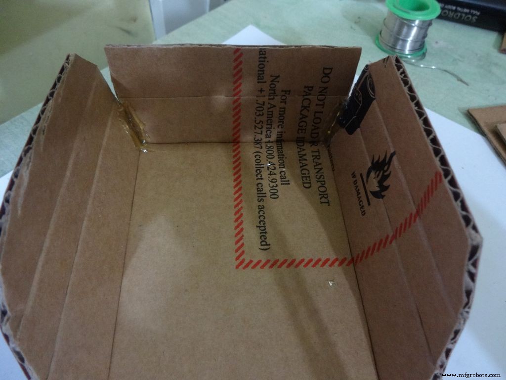
Voor de onderste helft of basis:
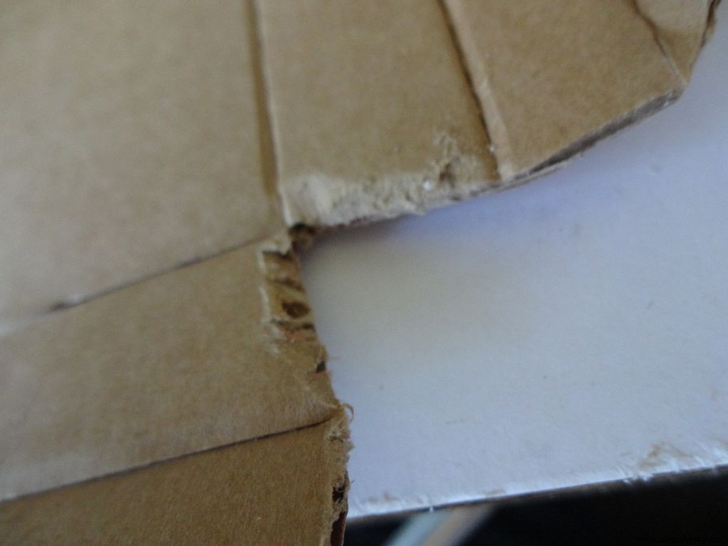
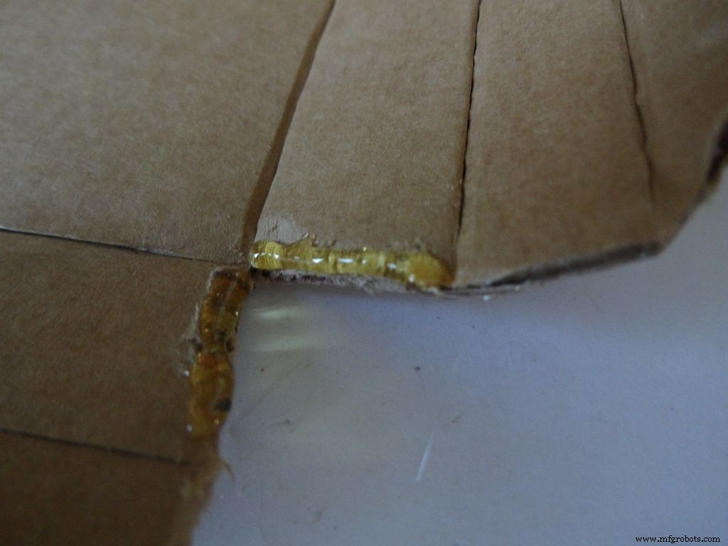
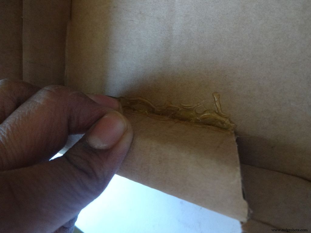
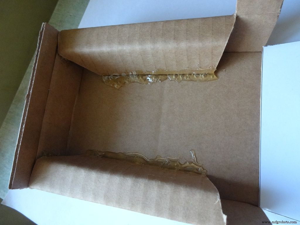
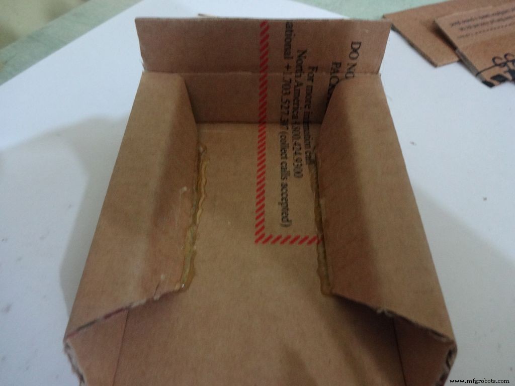
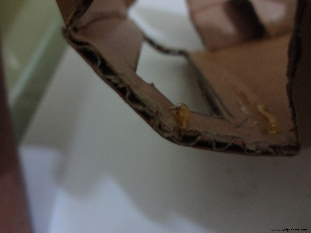
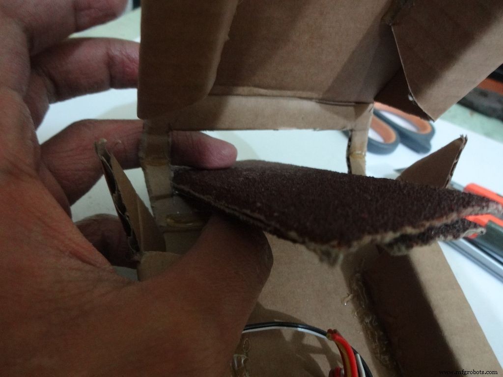
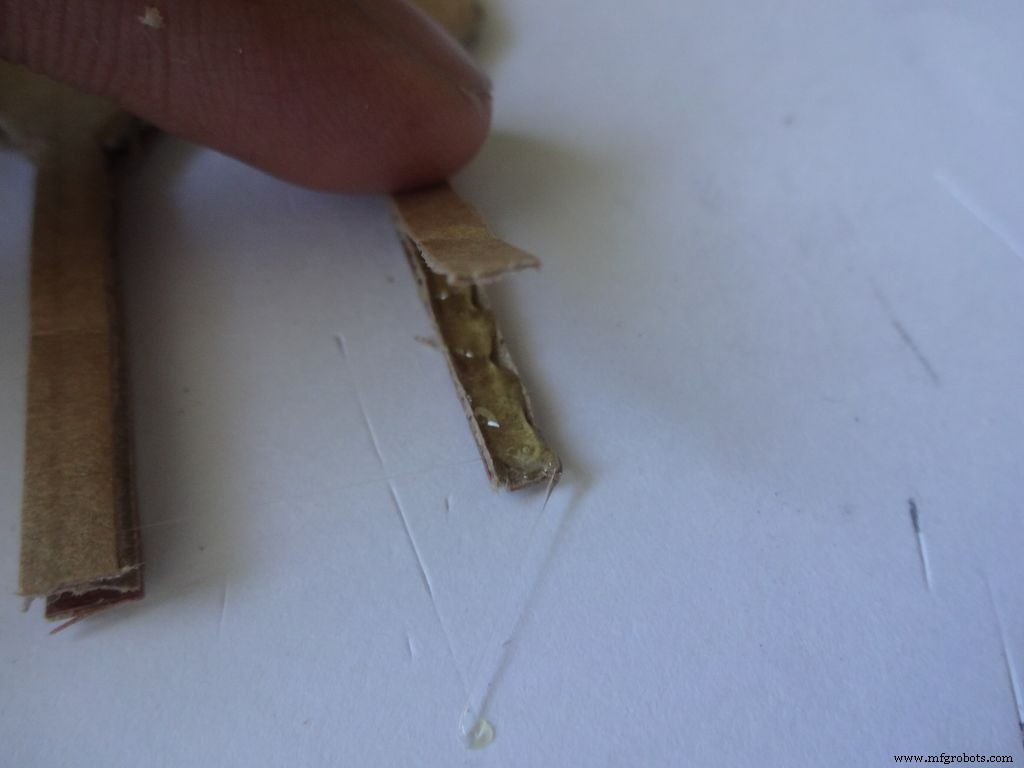
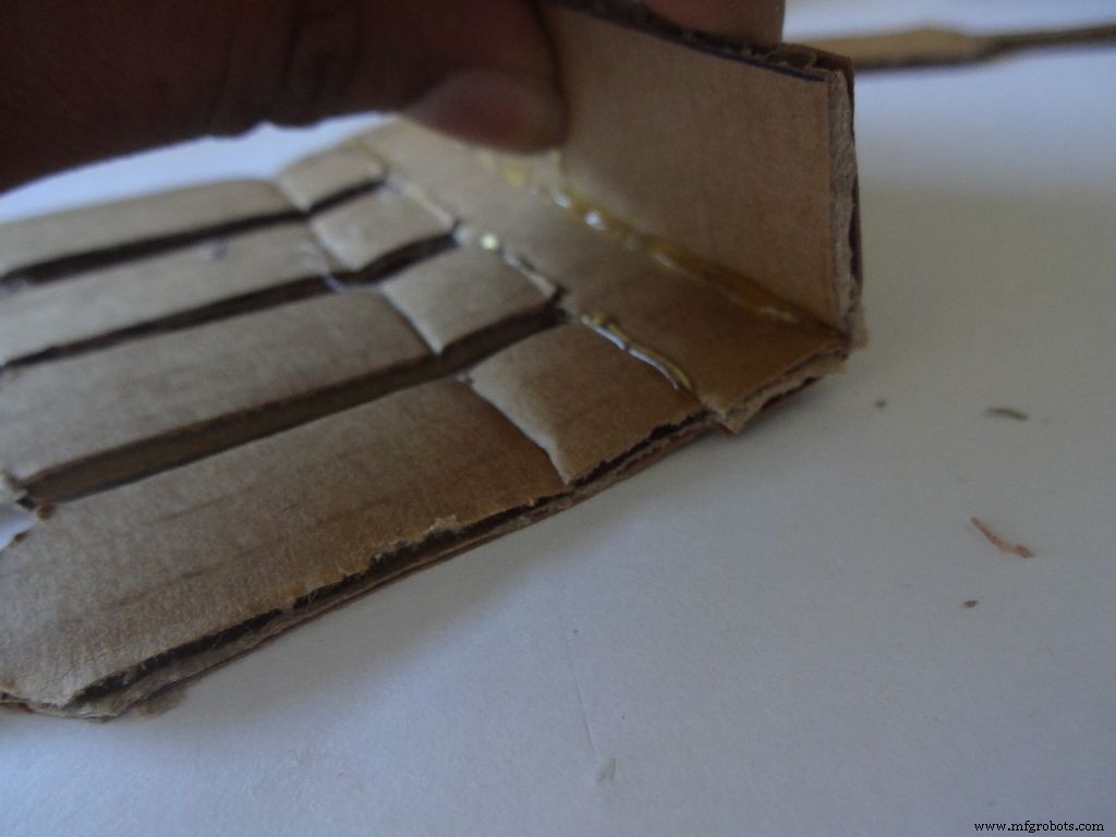
Gebruik het schuurpapier om de eerste vier randen schuin te schuren, hete lijm aan te brengen met een lijmpistool (één kant per keer), voeg toe en houd 30-60 seconden vast terwijl de lijm afkoelt.
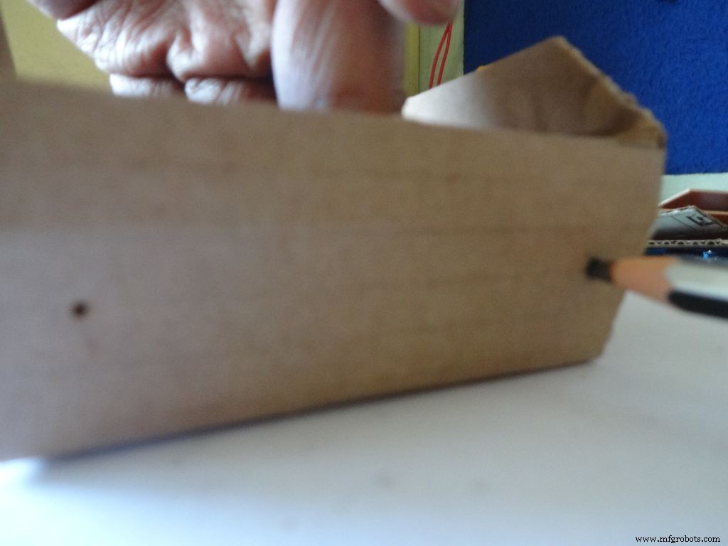
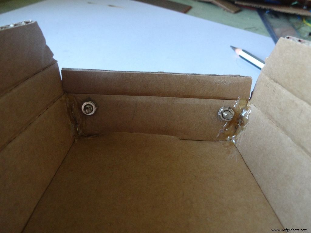
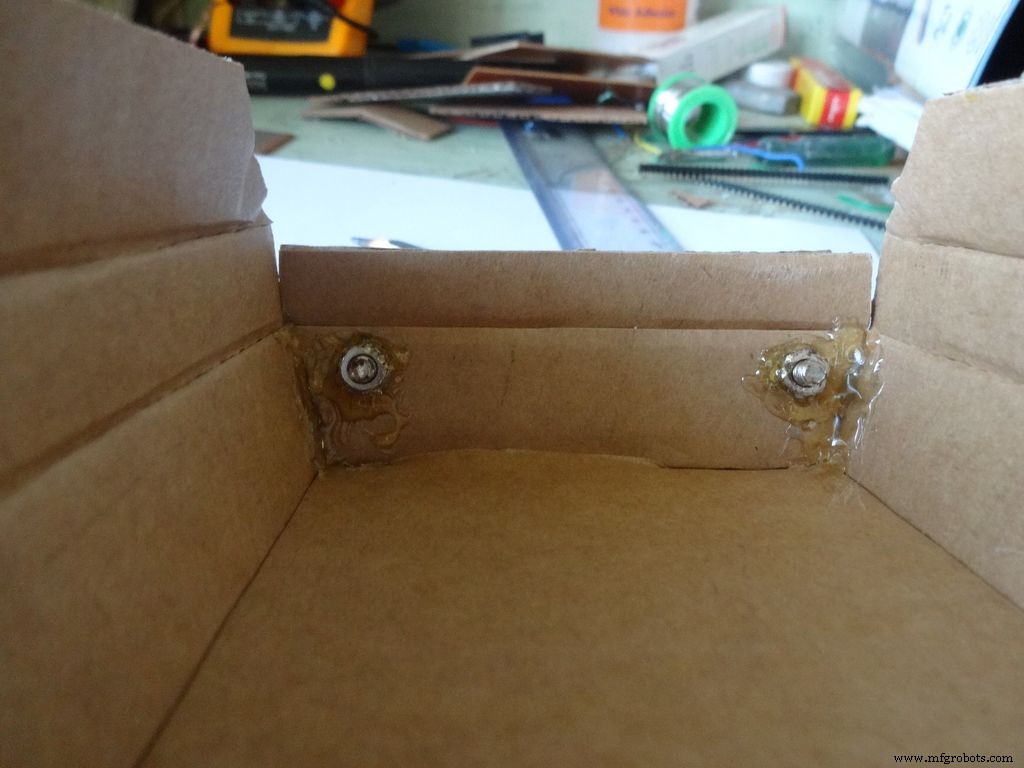
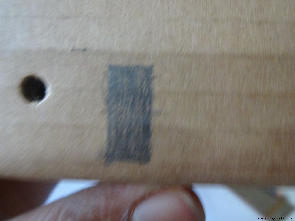
Maak twee gaten met een duimpin zoals afgebeeld en vergroot deze met een potlood net genoeg om de bout erin te passen. Draai de moer aan de binnenkant vast, breng hete lijm aan (alleen op de moer!), laat afkoelen. Verwijder de bout met een schroevendraaier.
Vouw vervolgens de twee zijflappen naar binnen en plak deze vast. Het buitenste deel van de flap moet licht hellend zijn en het middelste deel vlak.
Stap 10:De case maken - De schakelaars toevoegen
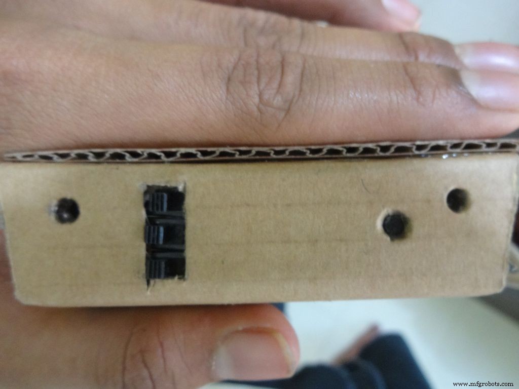

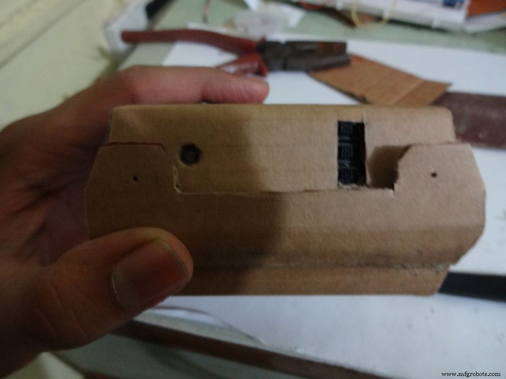
Neem de 3 schuifschakelaars met draden die we eerder hebben gesoldeerd, meet de geschatte afmeting van de benodigde rechthoek. Mark it on the left side of the box(left from the outside). Cut it with a cutter, sand it a bit on the inside to remove any material sticking out.
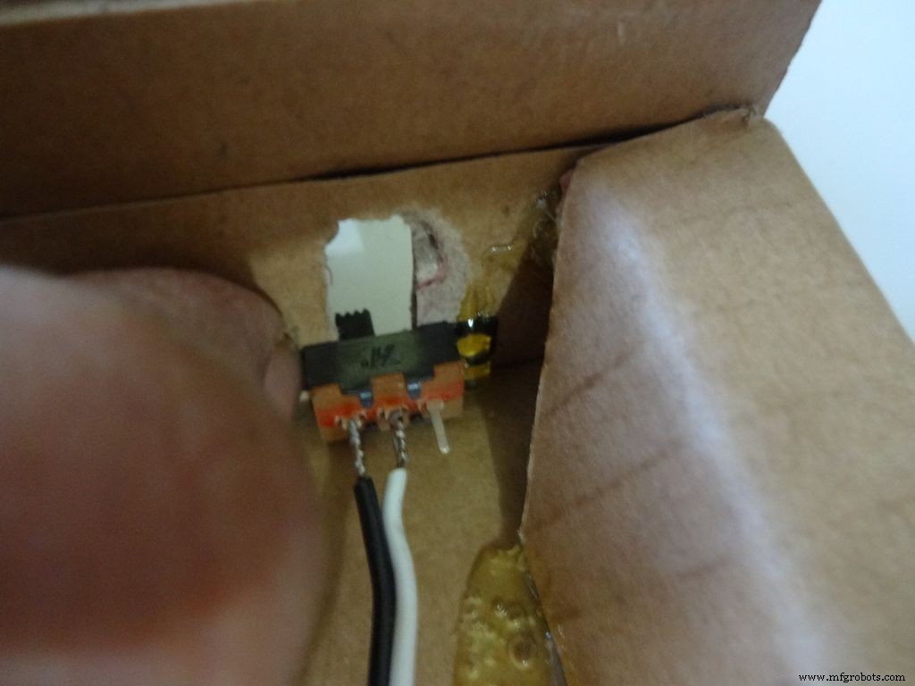
Keep the first switch in position and while holding it add glue on one side. Let it cool. Repeat with the other two as well, and then add glue on the remaining sides. Note:The wired pins of the switches should be on the same side.
Make another hole on the other side for the reset pushbutton. Hold the button in place and add glue. Fold the lower flap inwards and stick it.
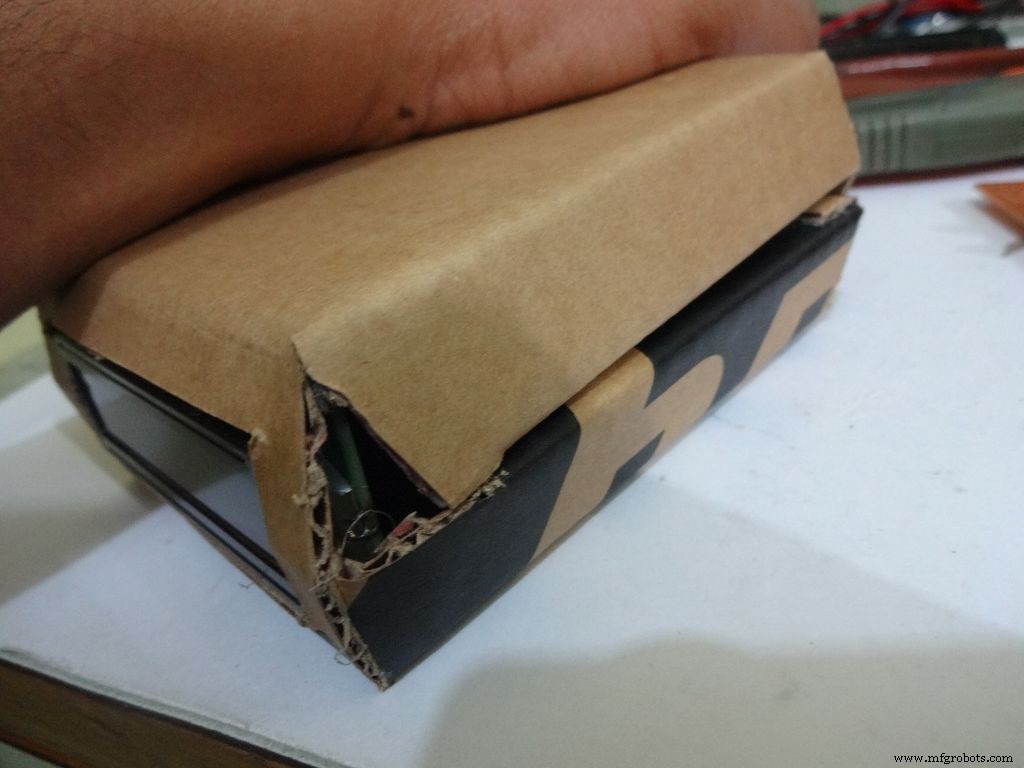
Step 11:Making the case - Top half or cover
Sand the edges and stick the side flaps inwards(just like the base) for the top half
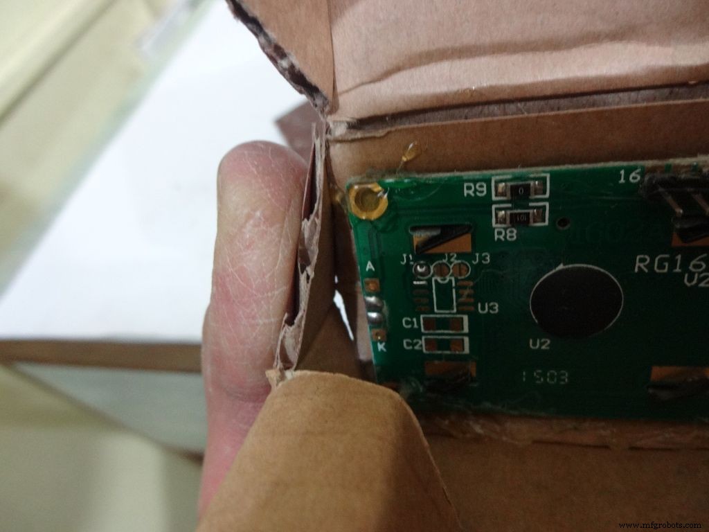
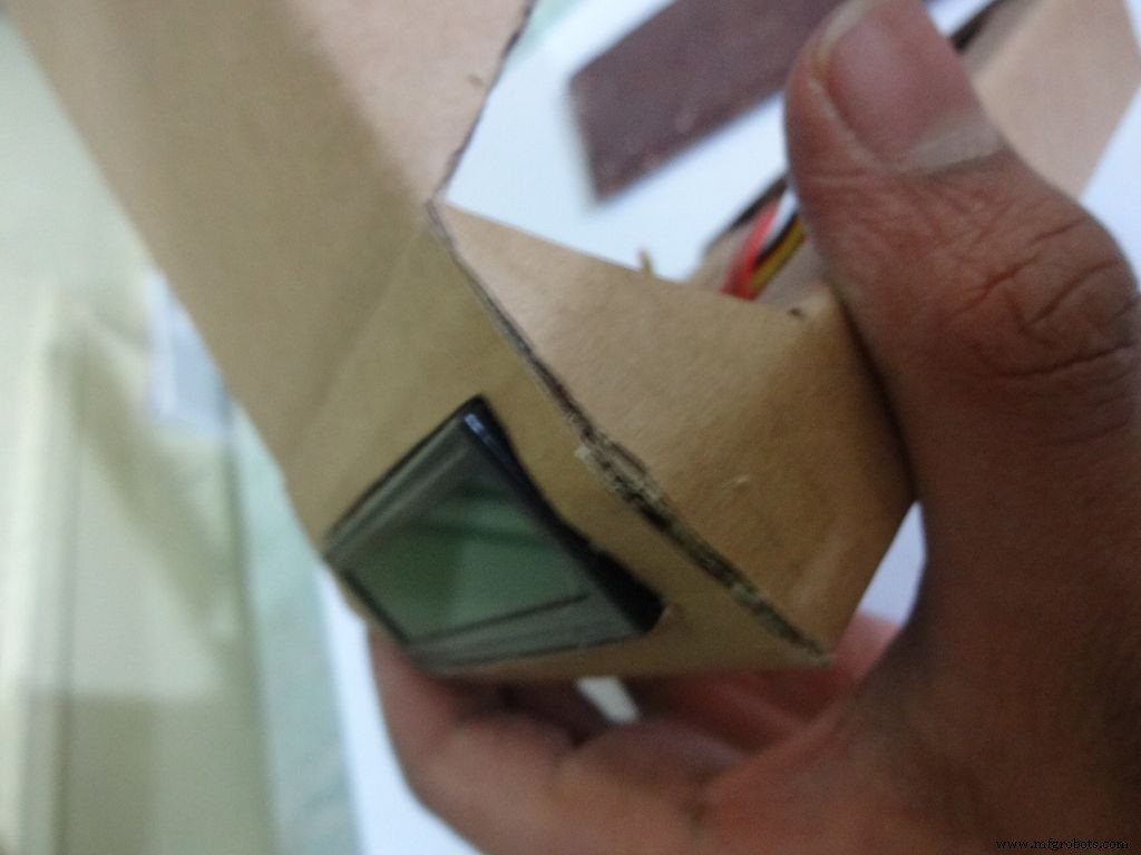
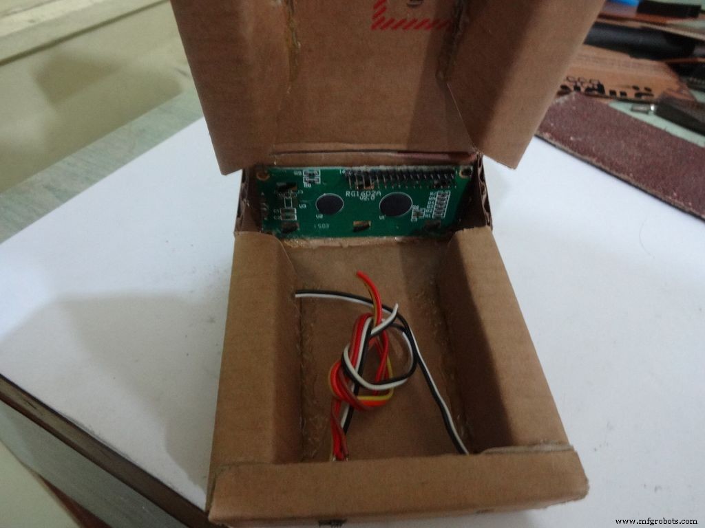
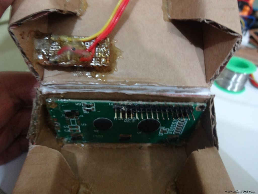
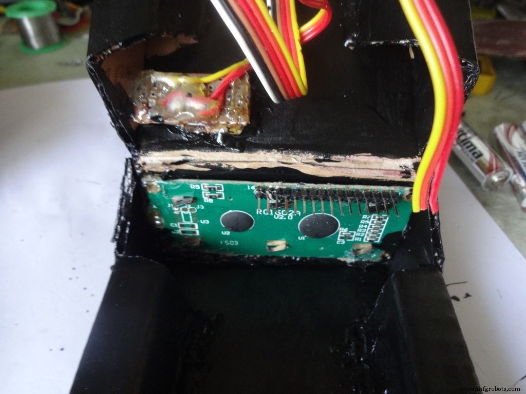
Step 12:Making the case - Adding the LCD
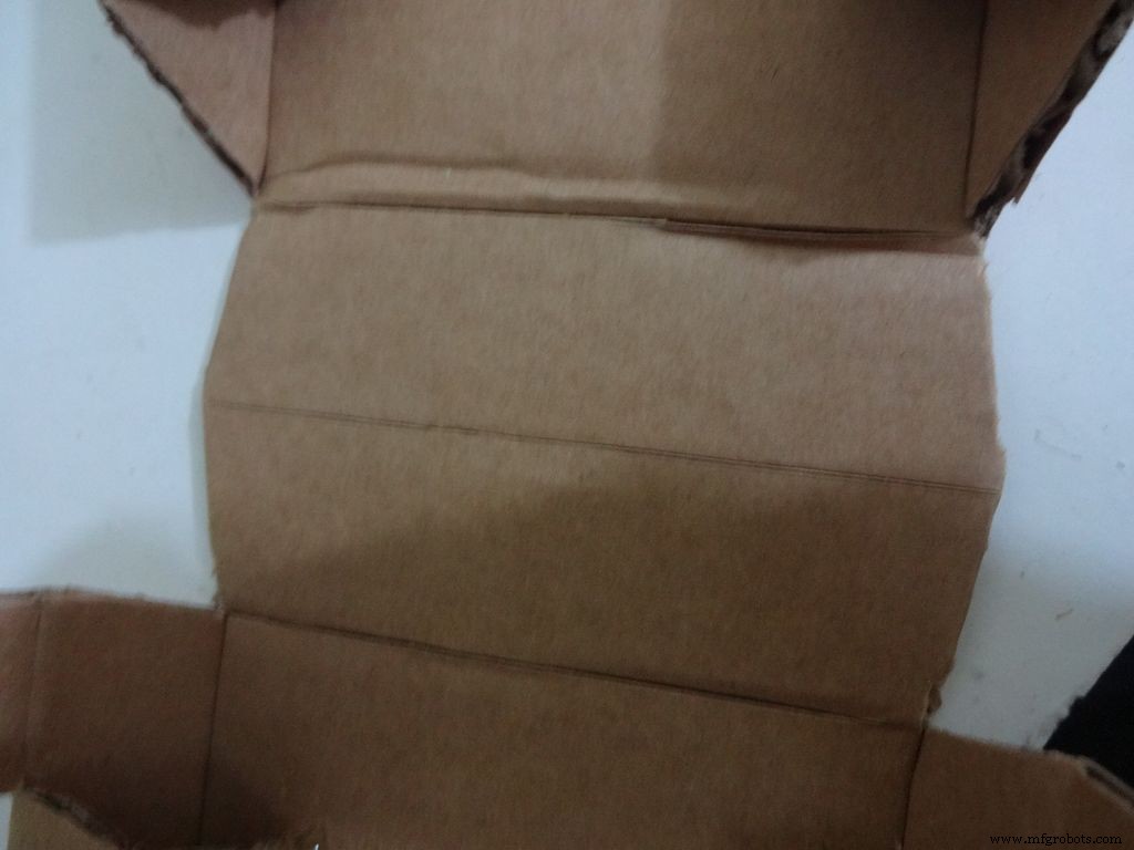
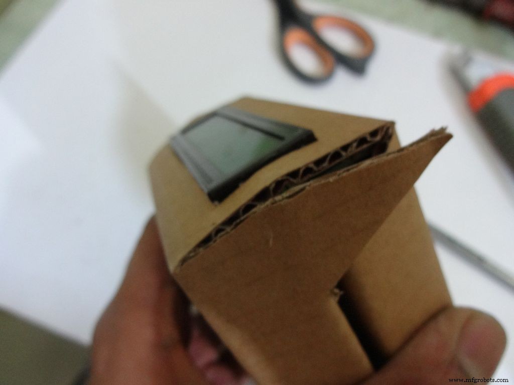
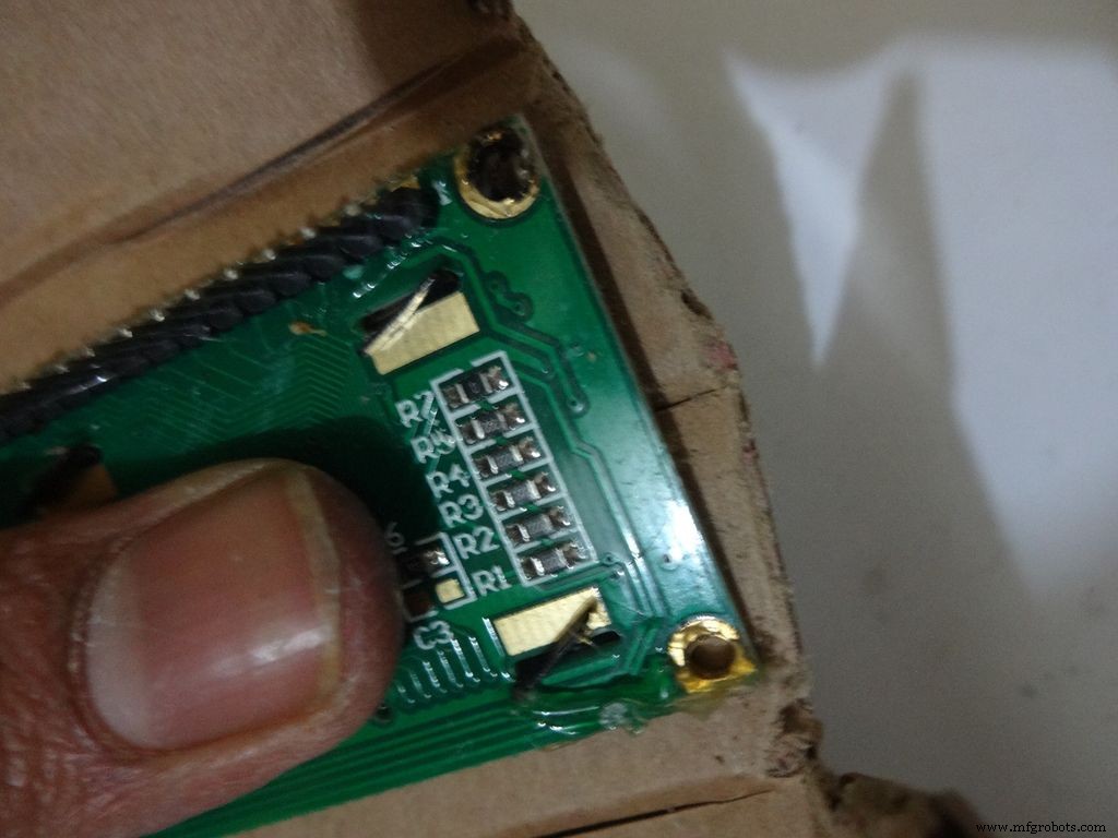
Crease the middle line. (Didn't do it earlier as it is delicate and gets loose soon).
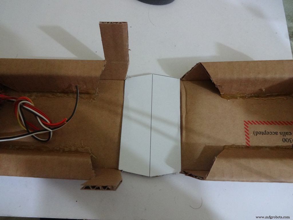
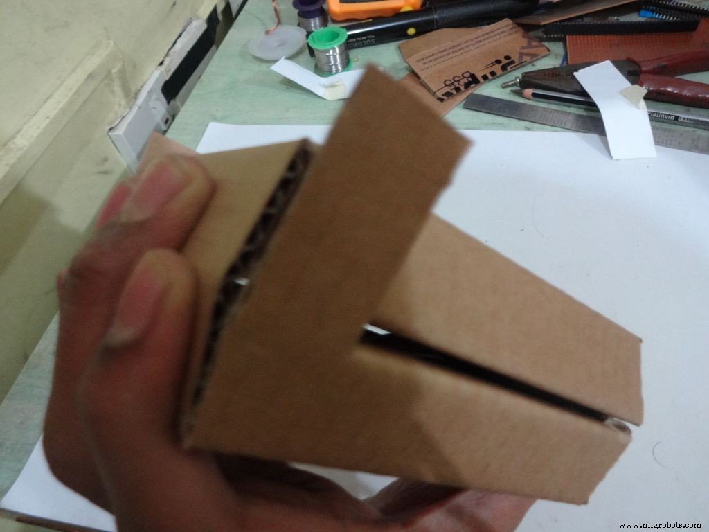
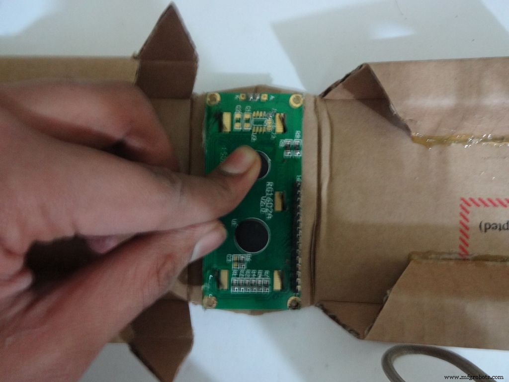
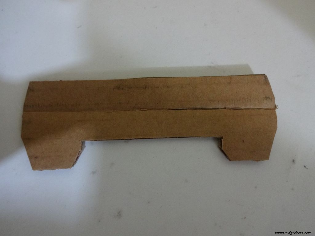
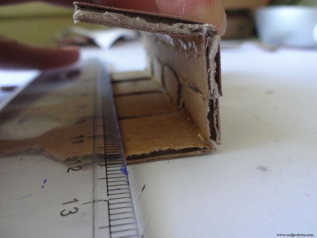
Fold the cover over to the base and check whether everything looks alright, sufficient spacing should be left for the IC pins. (See photo)
Cut the covering flaps as shown in the images.
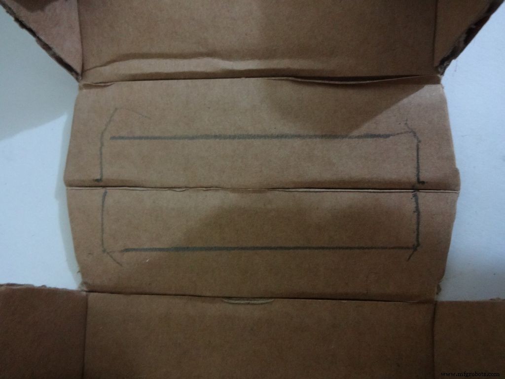
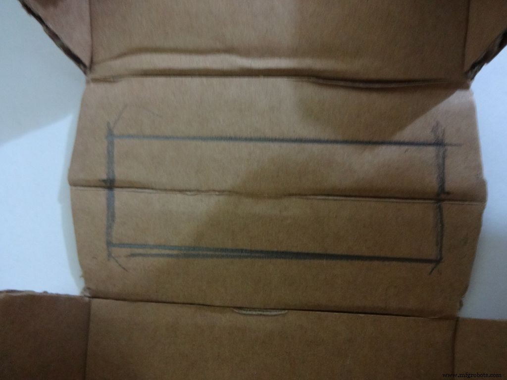
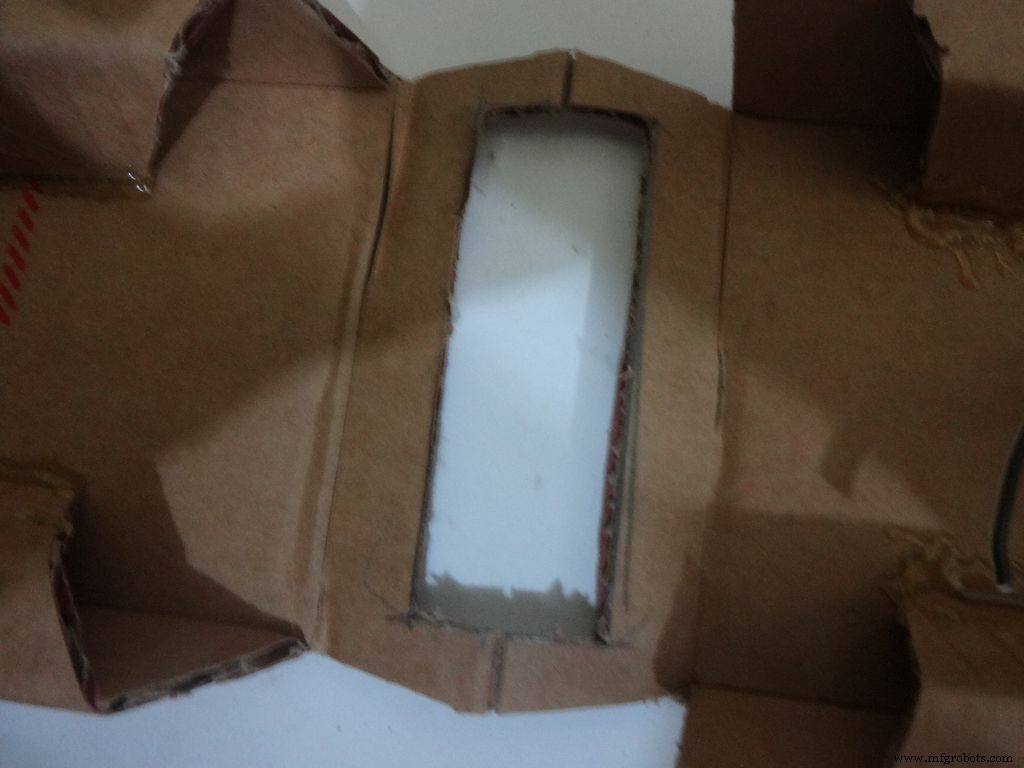
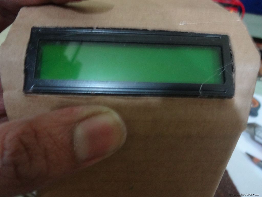
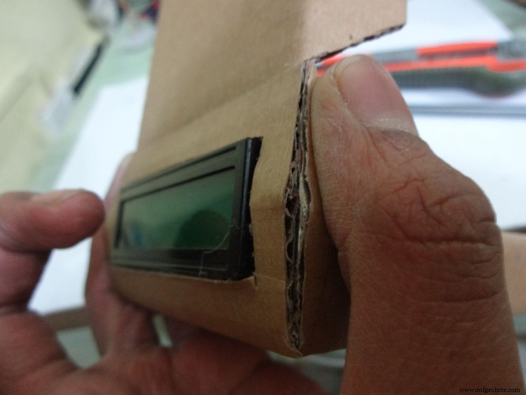
Keep the LCD at the center of the LCD Area, mark it with a pencil. Using a ruler, make the rectangle properly and cut it carefully using a cutter. Fold the LCD window and apply glue to the hinges to keep them at their correct position. Insert the LCD and make any modifications if required.
Finally, apply glue to the four corners(don't put excess) of the LCD and place it in position.
Step 13:Making the case - Final flaps
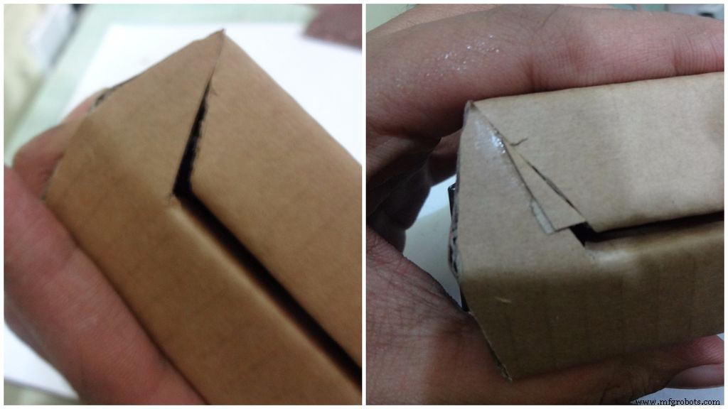
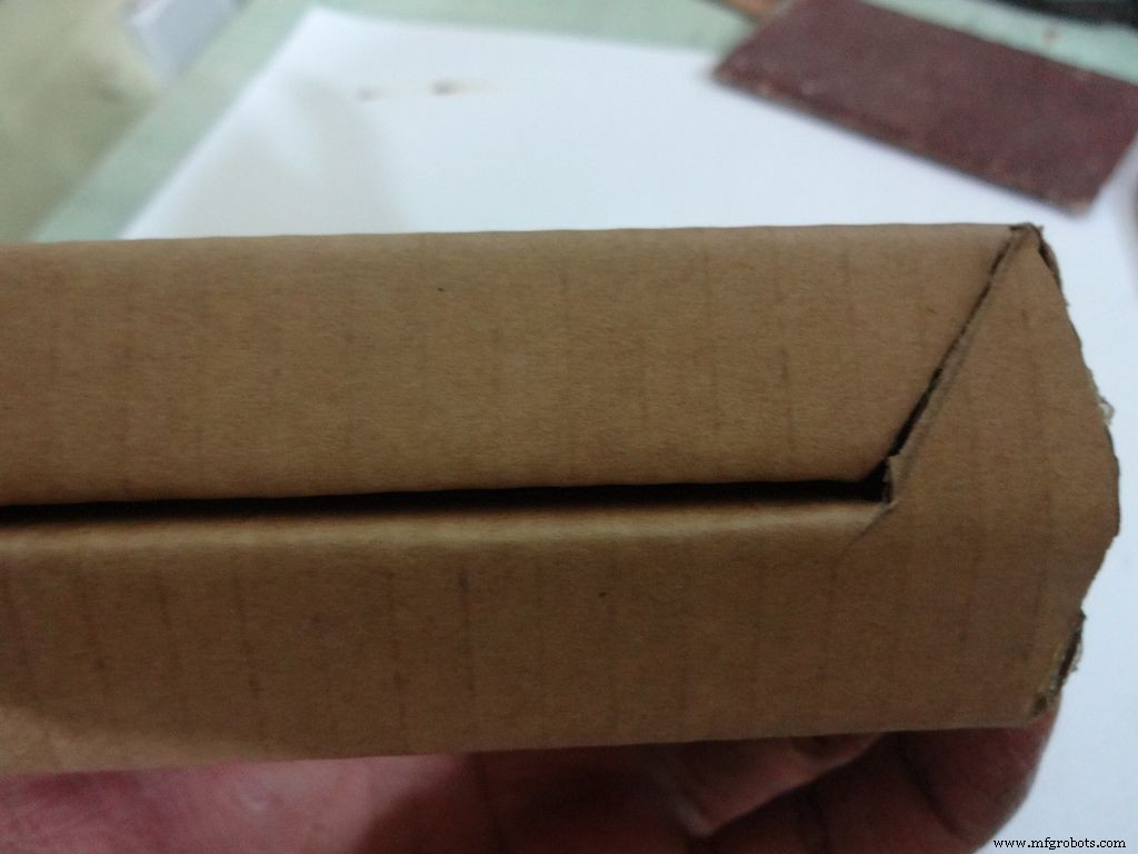
Sand, trim and close the tringular flap.
Make a small piece as shown and stick it to the cover. Make two holes, widen them with a pencil for inserting the bolt and locking the cover to the base.
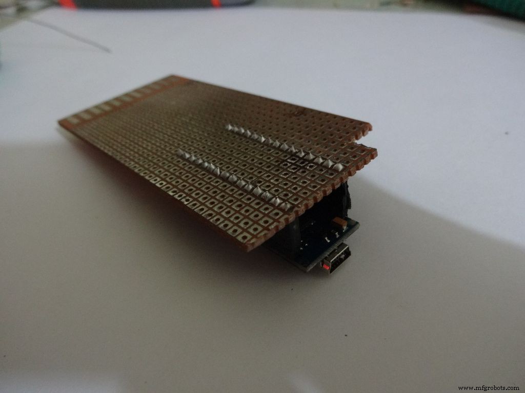
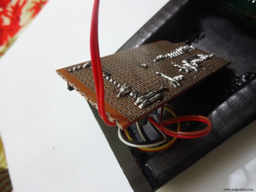
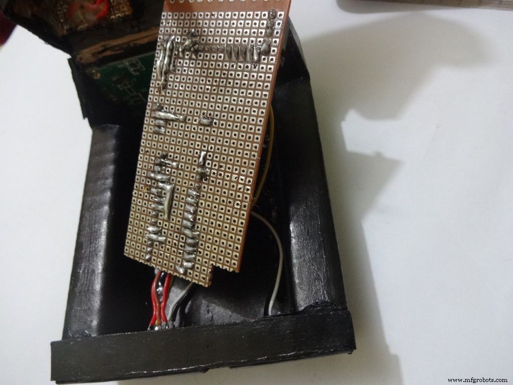
Step 14:The Circuit Board -- Making it fit

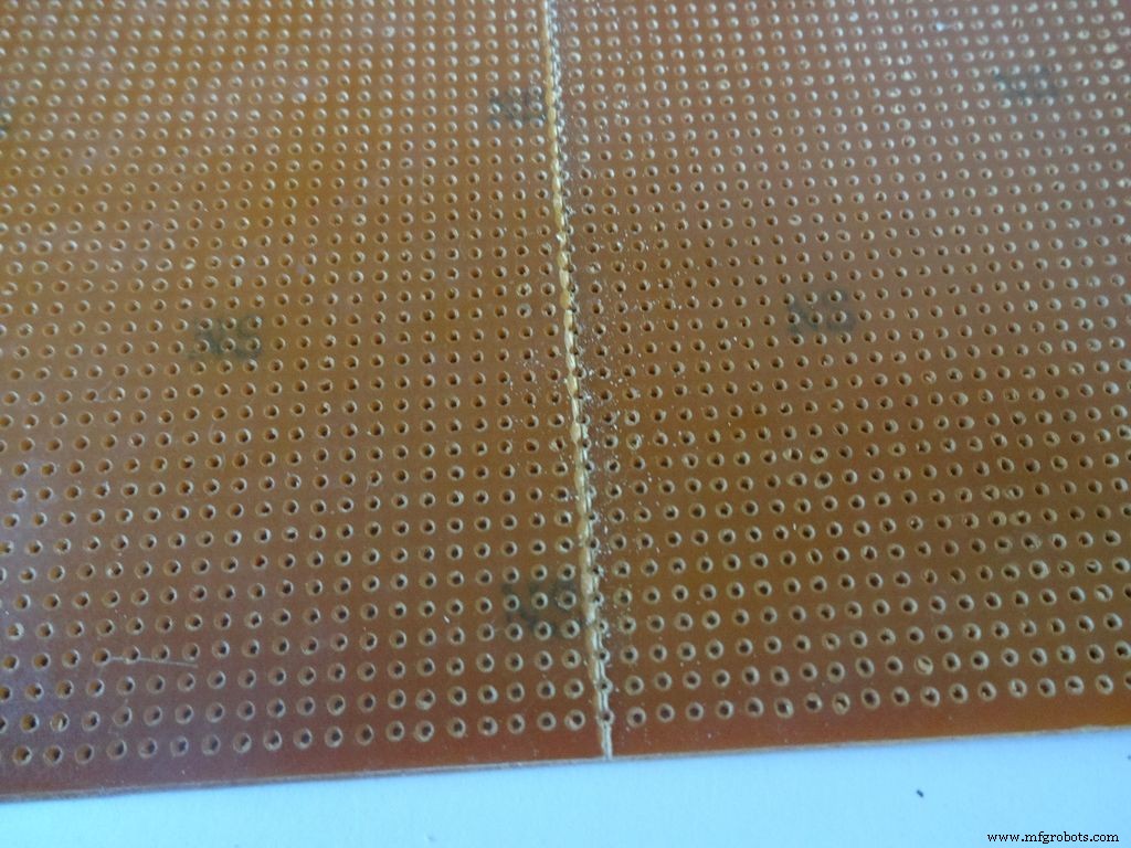
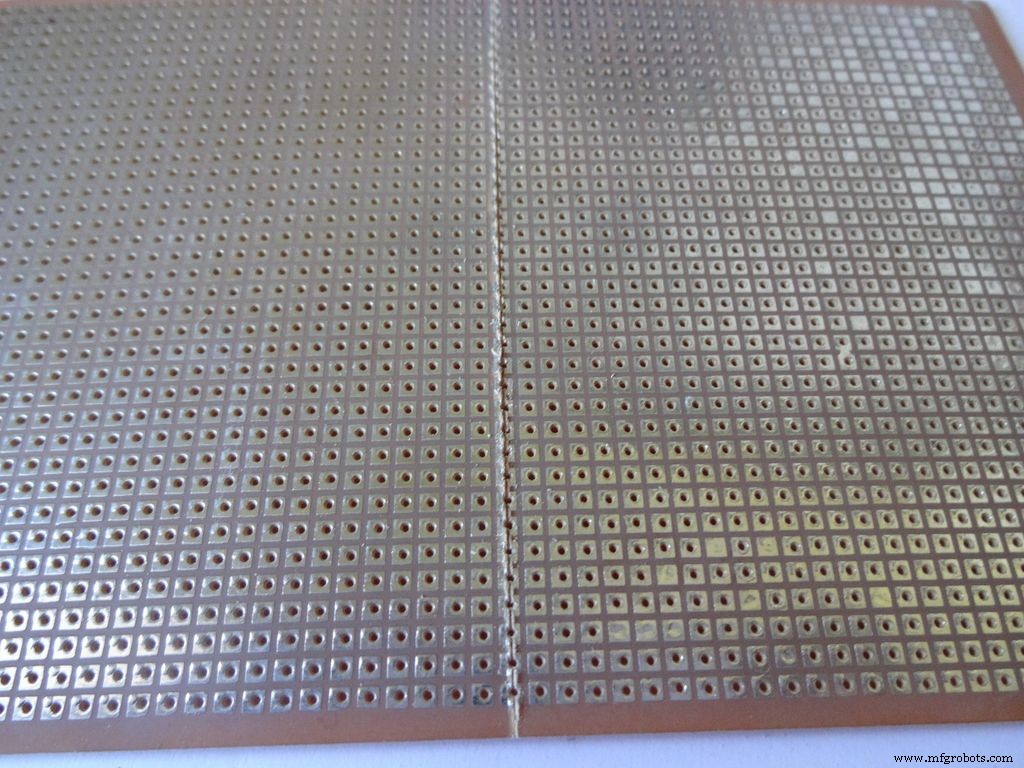
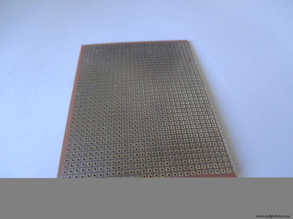
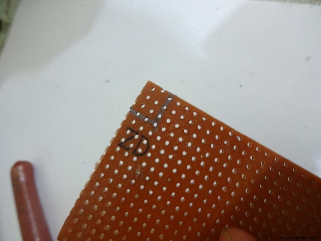
Cut the General purpose PCB to the right size such that it fits properly in the case. Mine is 2x4inches. To cut it, use the ruler and cutter and swipe it multiple times on both sides and it breaks off easily then.
Place it inside. If the glue from the side flap lifts the PCB up, reheat the glue to flatten it or lessen the size of PCB a bit.
Cut a small part so that the 3 switches fit in and PCB goes entirely inside.
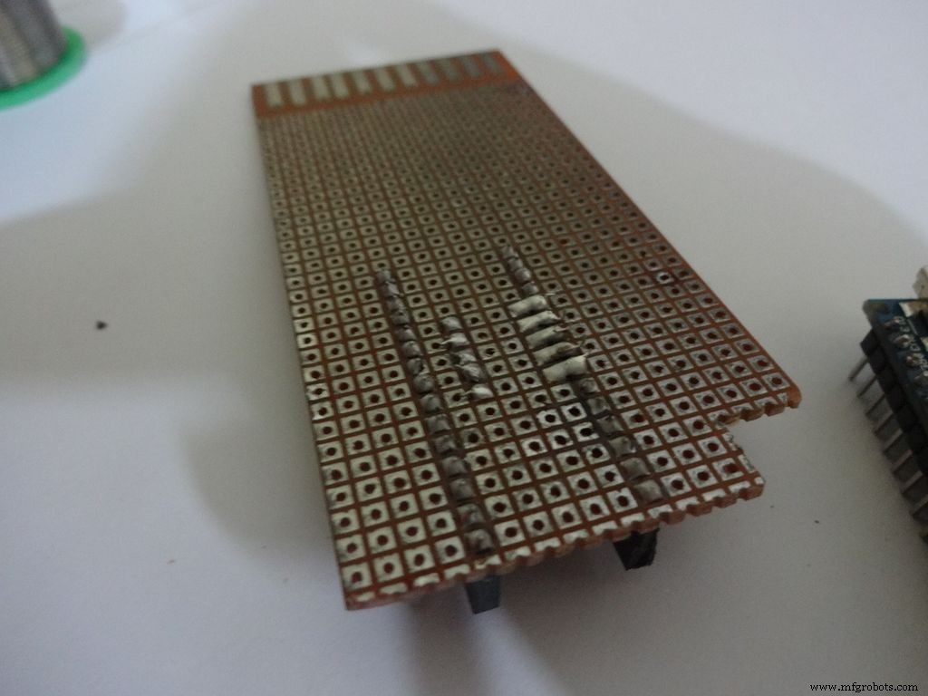
Step 15:The Circuit Board -- Arduino Nano

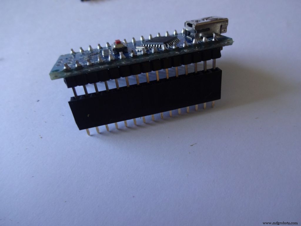
Cut female header pins of the right size for the Arduino.
Place it at the center edge of the PCB and solder all the pins.
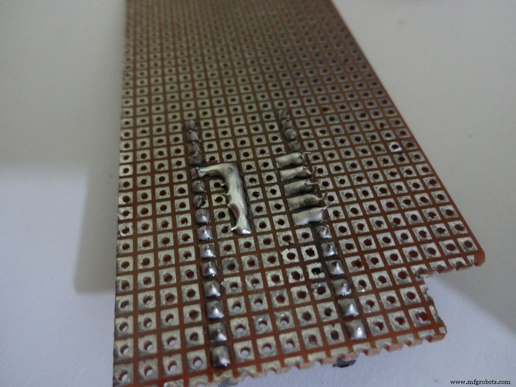
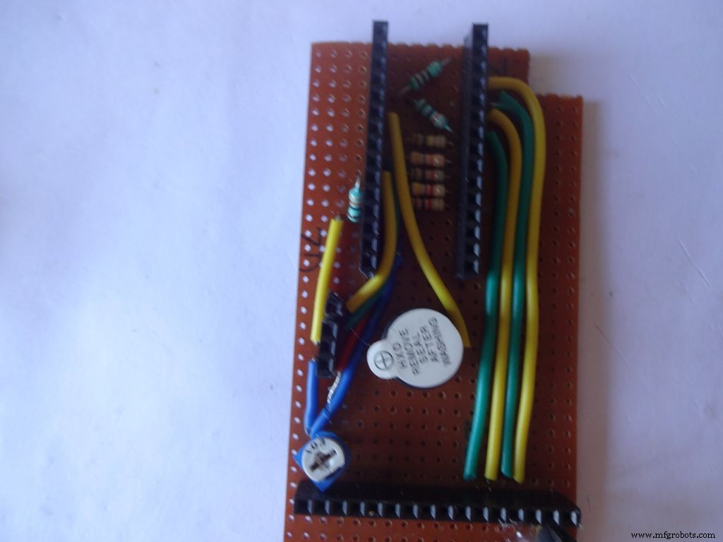
Step 16:The Circuit Board -- Ohmmeter
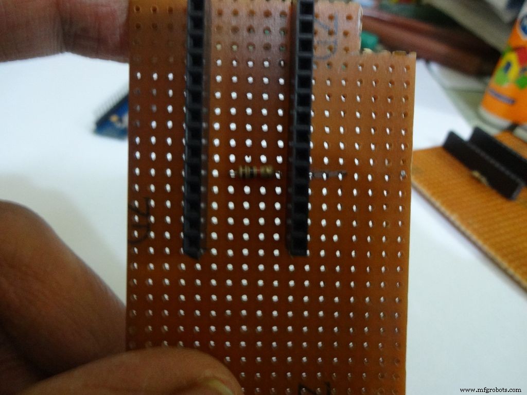
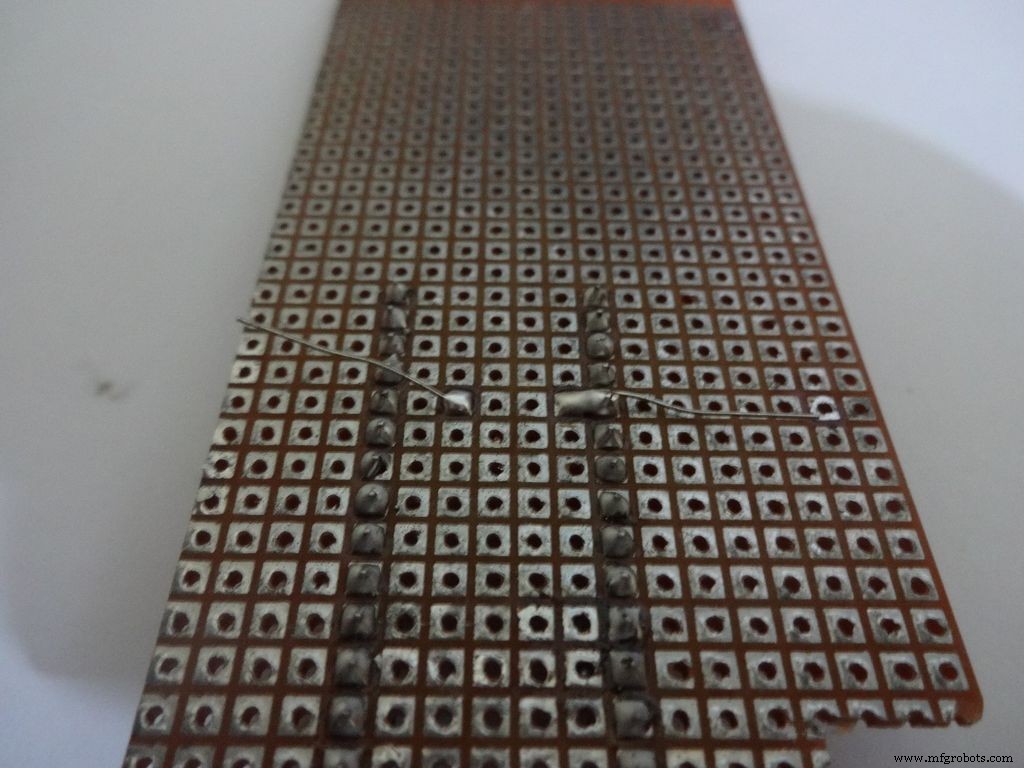
Before making any connections on the PCB please double check from the final Circuit Design.
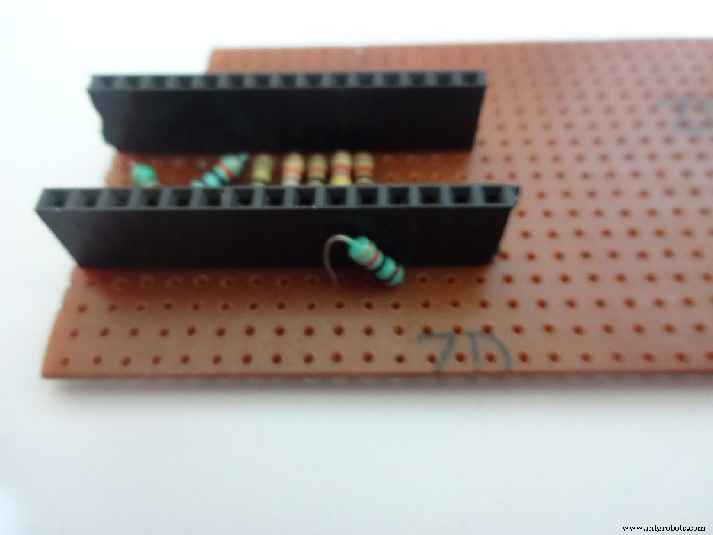
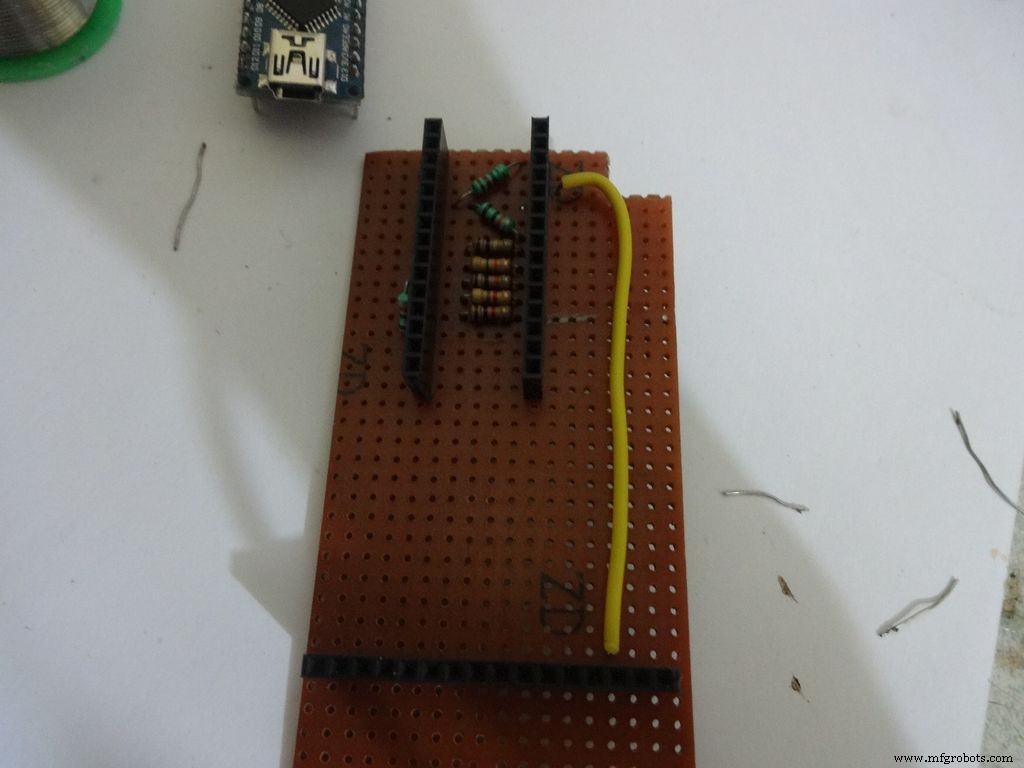
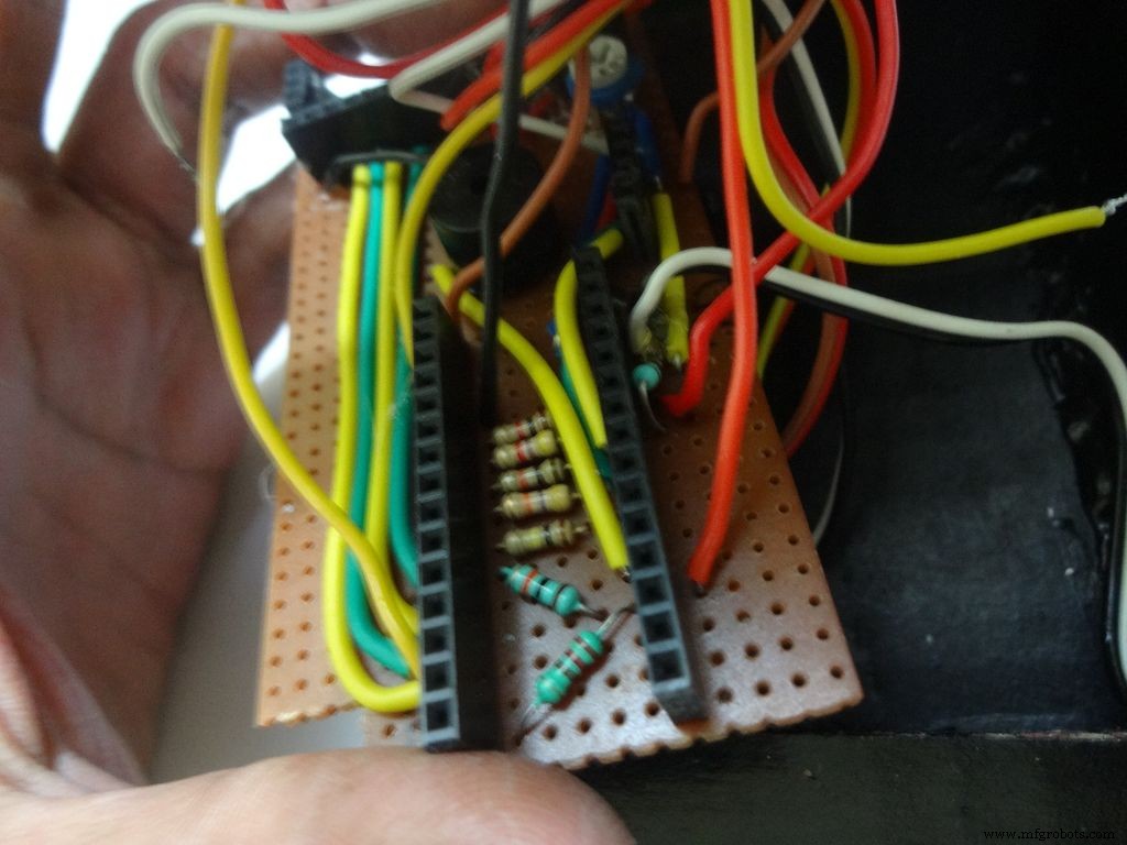
For the ohmmeter start by adding a 1k Ohm resistor to pin D2 of arduino. Place the arduino and carefully mark the pin. On the reverse side, bend as shown and solder it.
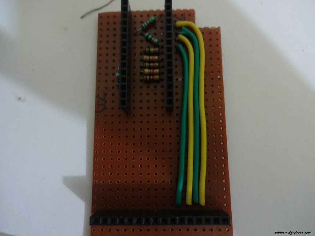
Do the same with the other 4 resistors, 4.7k, 10k, 47k and 100k Ohm.
Note:keeping all the tolerance bands(gold band) on one side is a good practice, eg UP and RIGHT.
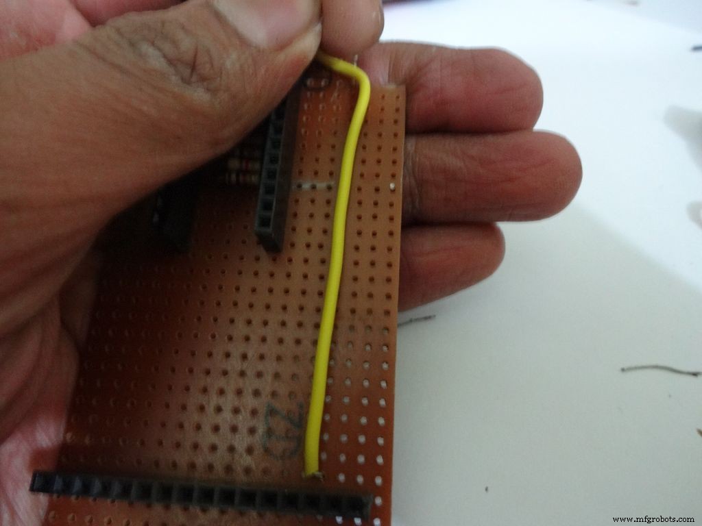
Combine the second ends of resistors and solder it to A7 .
Step 17:The Circuit Board -- Capacitance Meter and Diode Test
Capacitance Meter:
Solder a 220 Ohm resistor from D12 to A0 . And a 10k Ohm resistor from A0 to D7 .
Note: D7 (digital pin) is also used for LCD data pin D4 .
Diode Test:
Solder the 10k Ohm pullup resistor from A6 to +5V .
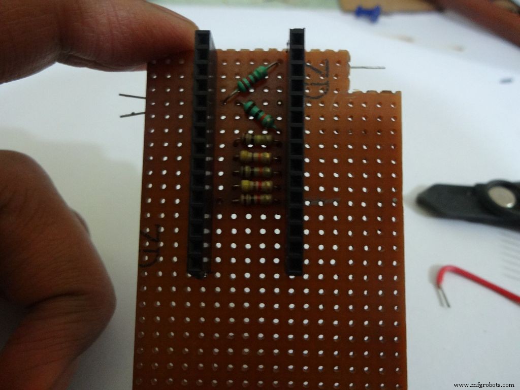
Step 18:Making connectors for LCD
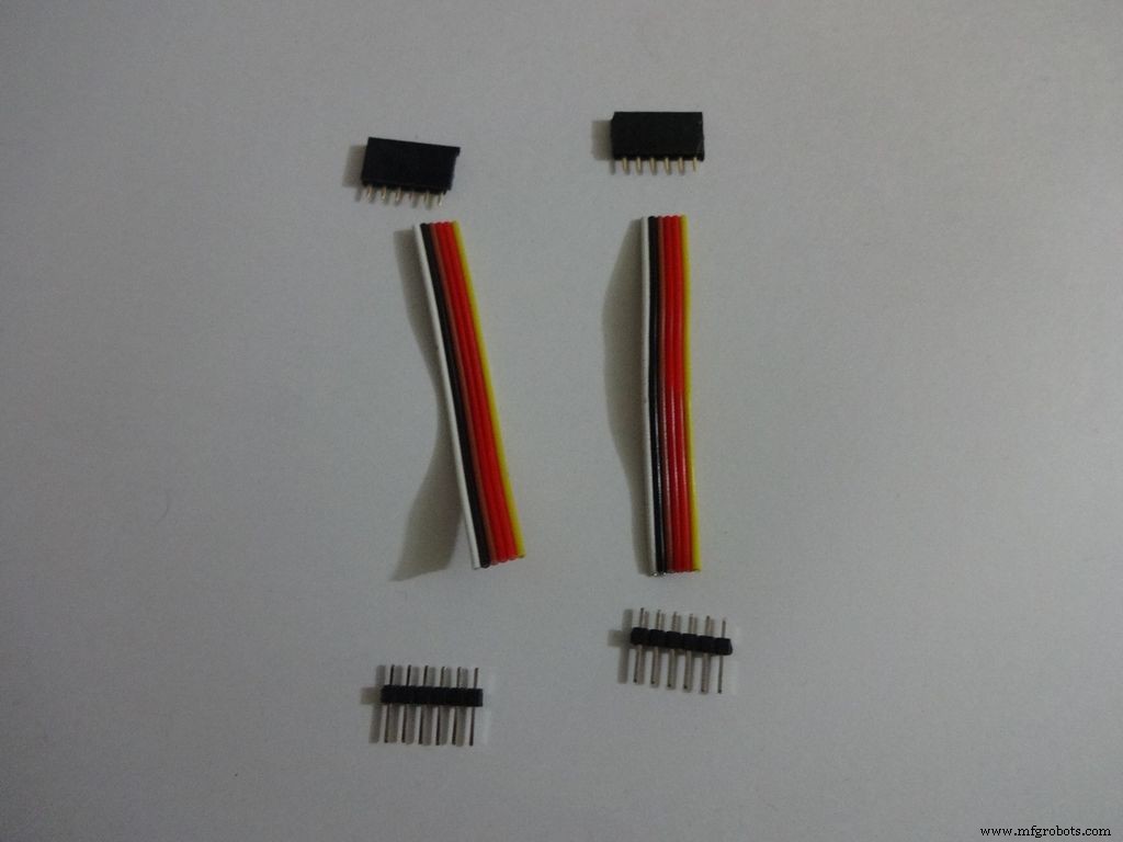
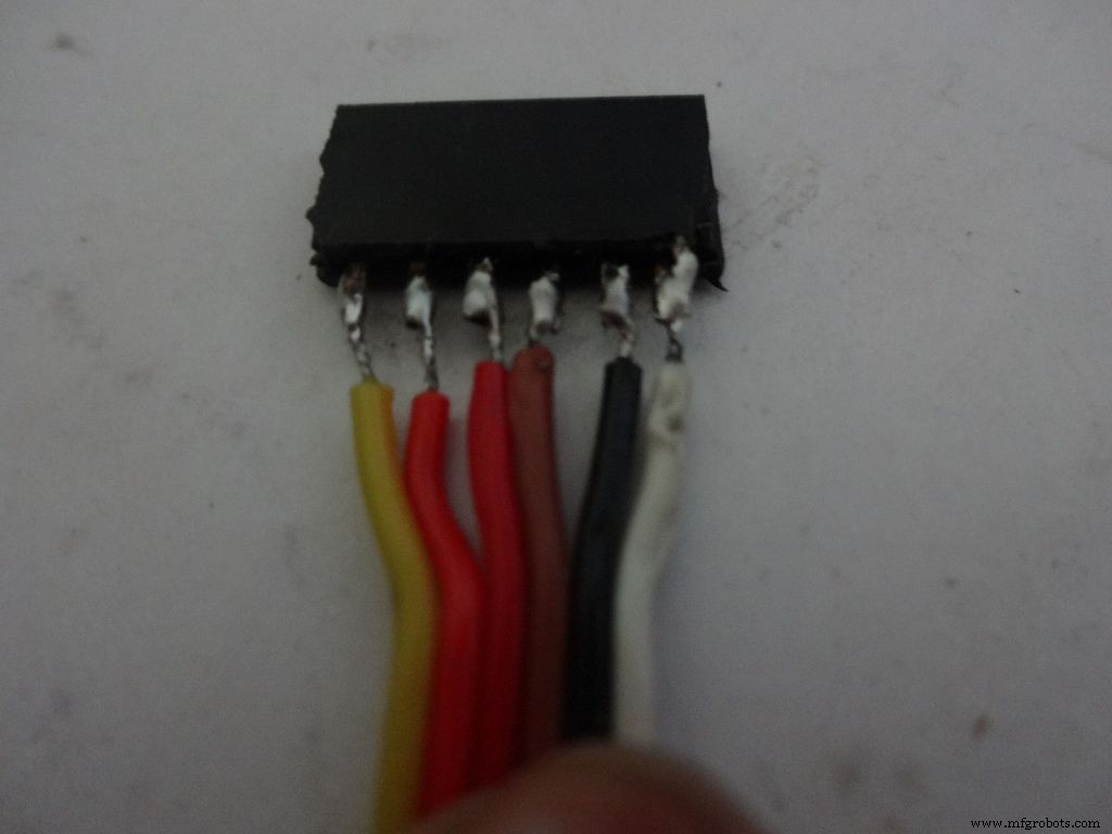
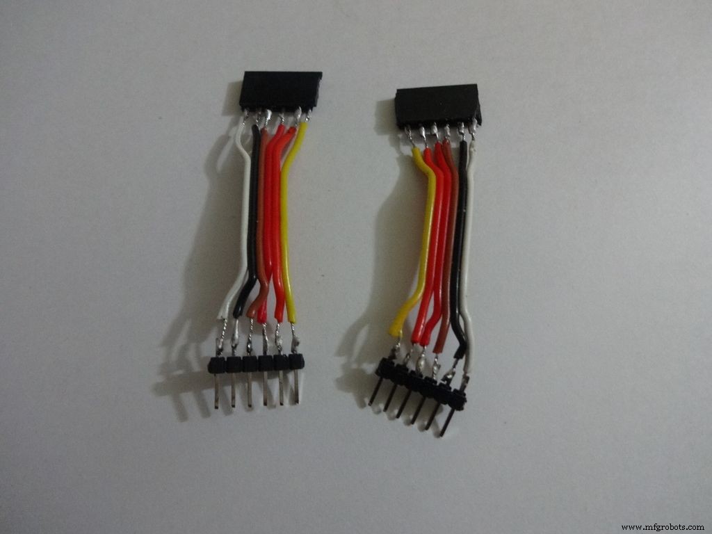
We just use the first 6 and last 6 pins on the LCD. Pins D0-D3 are unused. So we will be making connectors for only the used pins. It is recommended that you do the same because plugging/unplugging a 16pin connector becomes very tough once the build is complete.
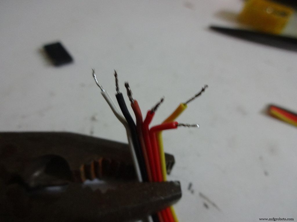
Cut 2x 6pin female and male header pins. Also take 6 wire ribbon cable, around 2-2.5 inches long.
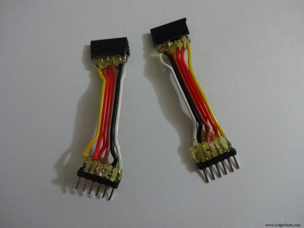
Strip the insulation and tin the leads. Also tin the header pins. Join them one by one just like the slide switches.
Apply hot glue to secure the wires.
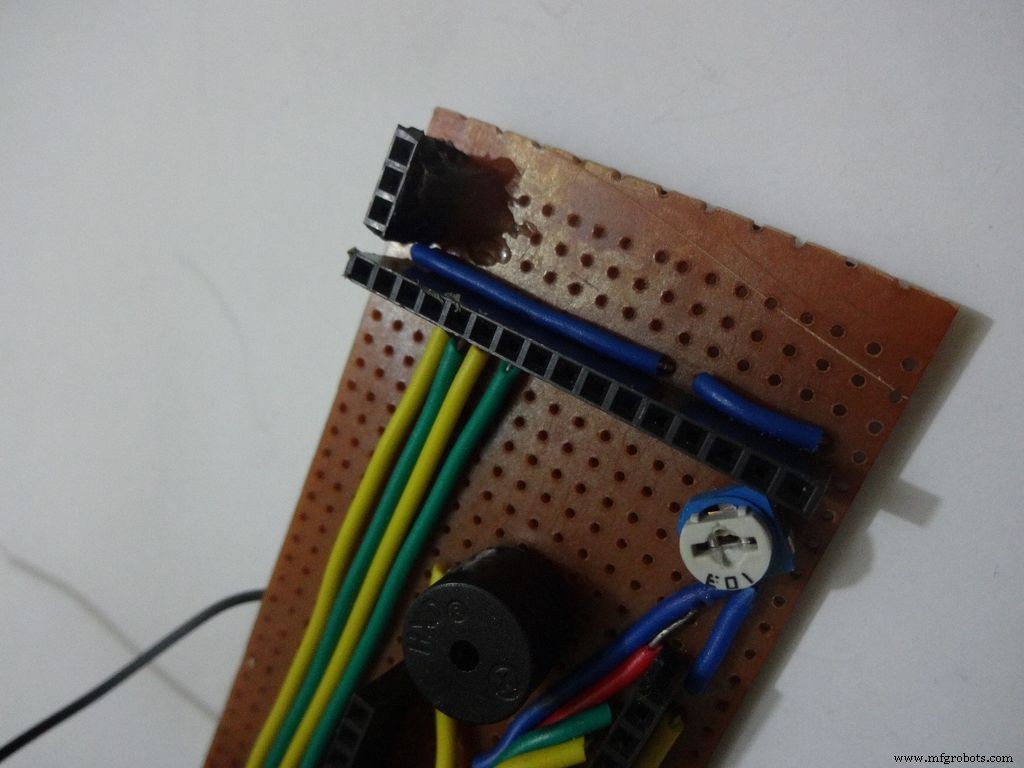
Step 19:The Circuit Board -- LCD connections
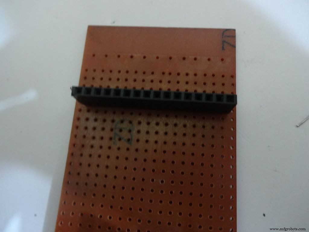
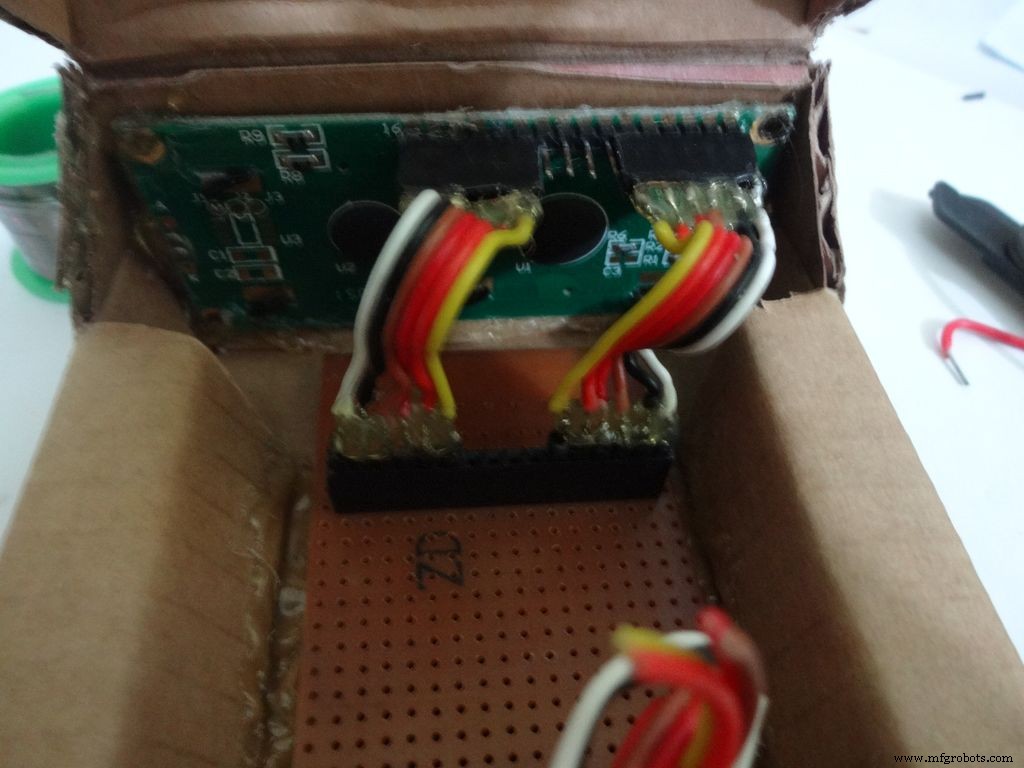

Place the PCB inside the case. Plug the connector to LCD and see where the female port should be on the PCB, solder it.
Make sure you leave 4-5 dot rows behind the LCD port. The Power switch will be added here later.
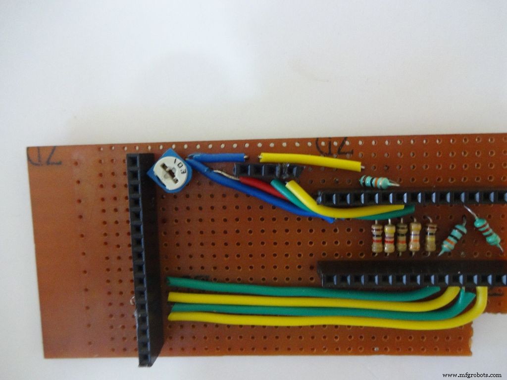
Measure the length of single stranded wire needed to connect data pins (D4 , D5 , D6 and D7 ) on the LCD to digital pins( D7 , D8 , D9 and D10 ) on the Arduino, respectively.
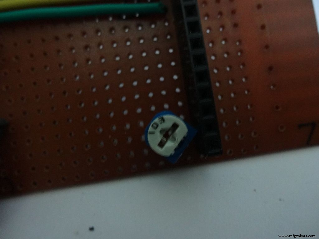
Add the 10k ohm potentiometer such that the side ends go to Vcc , GND and the middle pin to V0 .
Connect Vss(GND) on the LCD to GND , and Vdd to +5V . Also connect R/W to GND .
Arduino Pin
LCD
D7 D4 D8 D5 D9 D6 D10 D7 GND Vss(GND) +5V Vdd
Step 20:The Circuit Board -- RTC Module
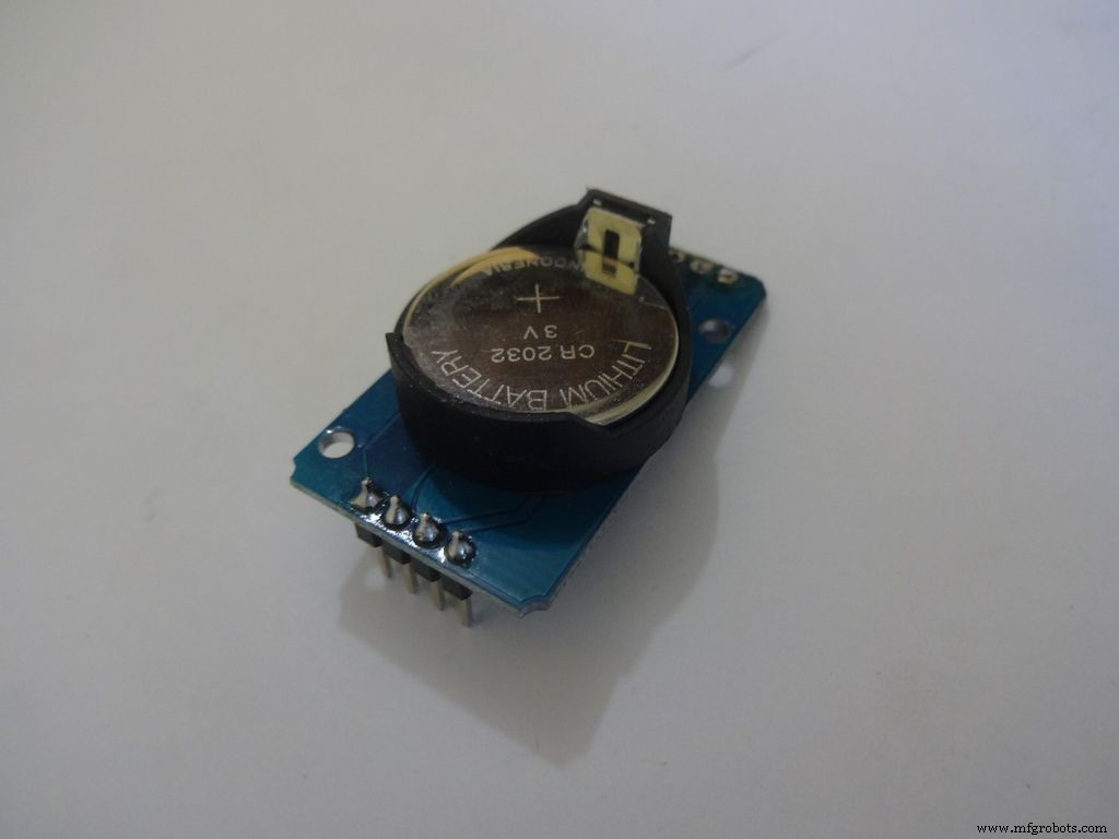
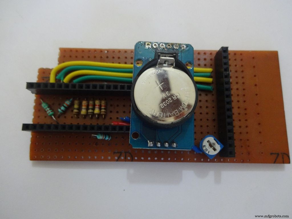
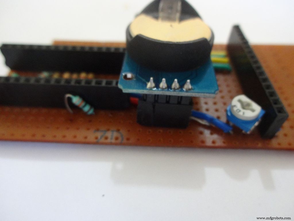
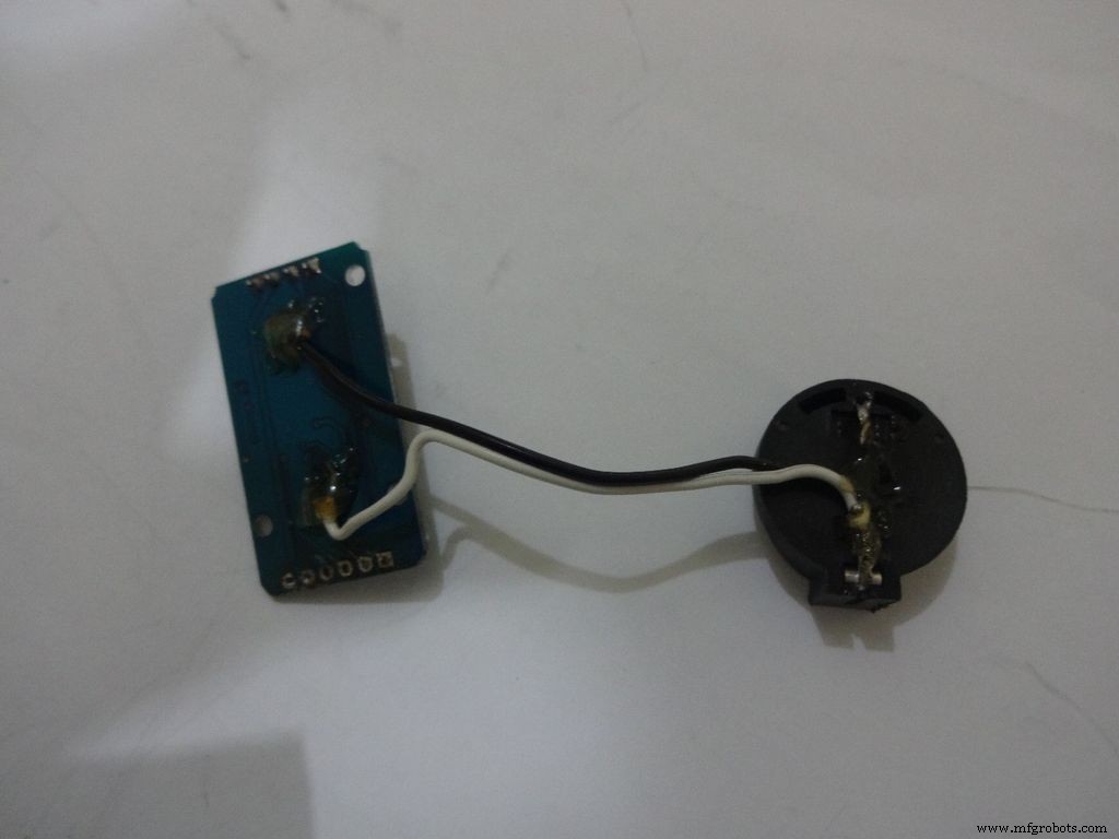
I desoldered the default 90 degree header pins on the module and added straight ones so that it fits flat on the PCB.
Solder 4pin female header pin and make connections to Vcc , GND , SDA to A4 and SCL to A5 .
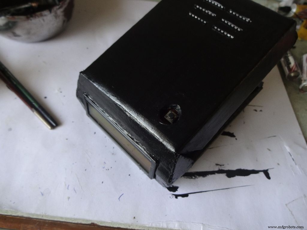
Step 21:Making the Case -- The mode button
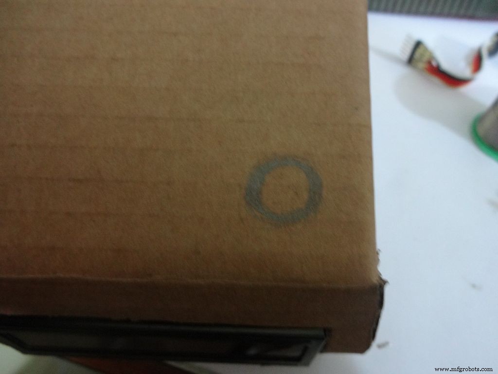
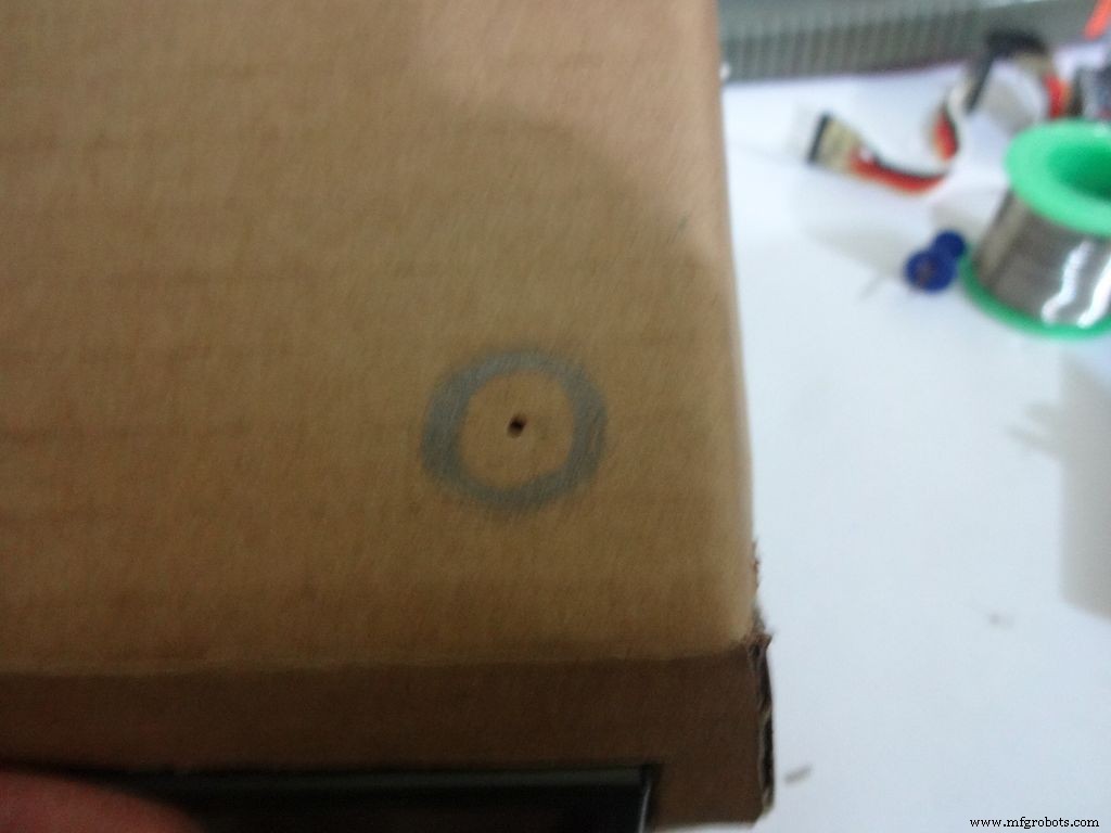
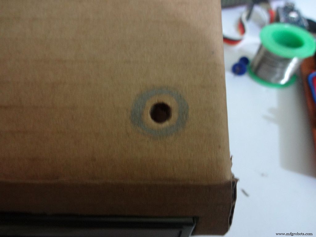
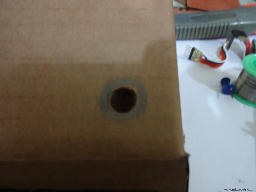
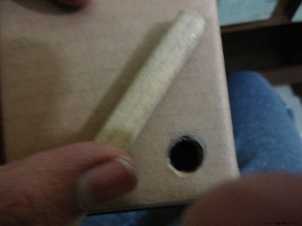
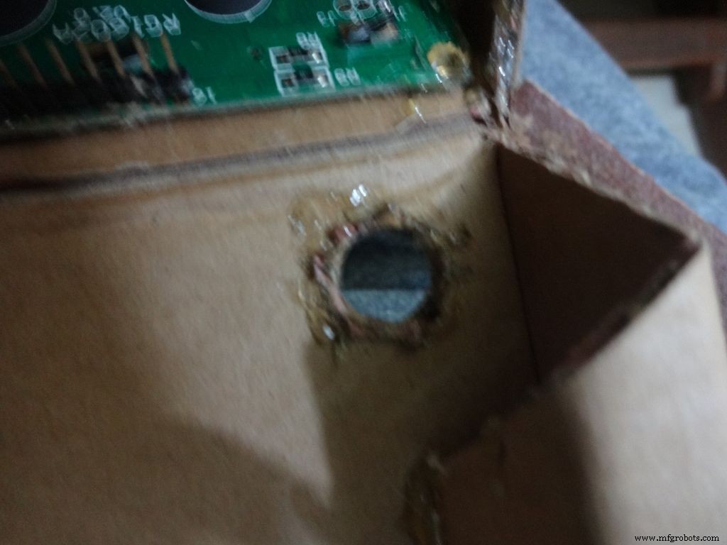


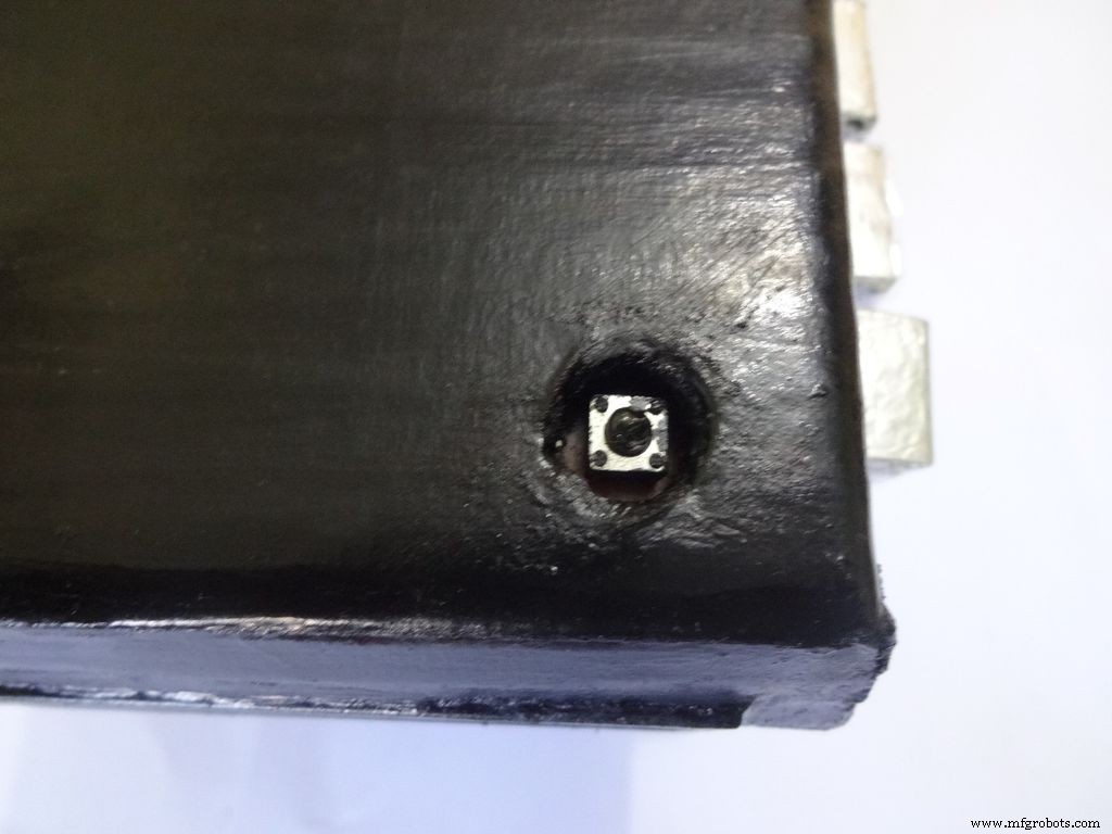
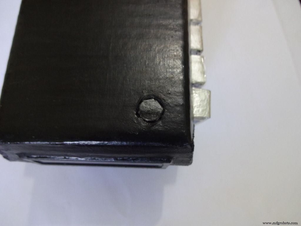
Mark a circle of about 1cm diameter at the pin1 corner of the IC case. mark the center with a pin, use a pencil to expand it. After that use some appropriate tool to increase the diameter to 1cm. Sand it on the inside and use hot glue to secure the hole.
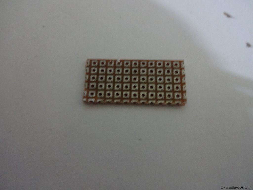
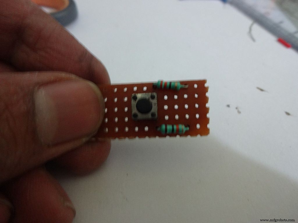
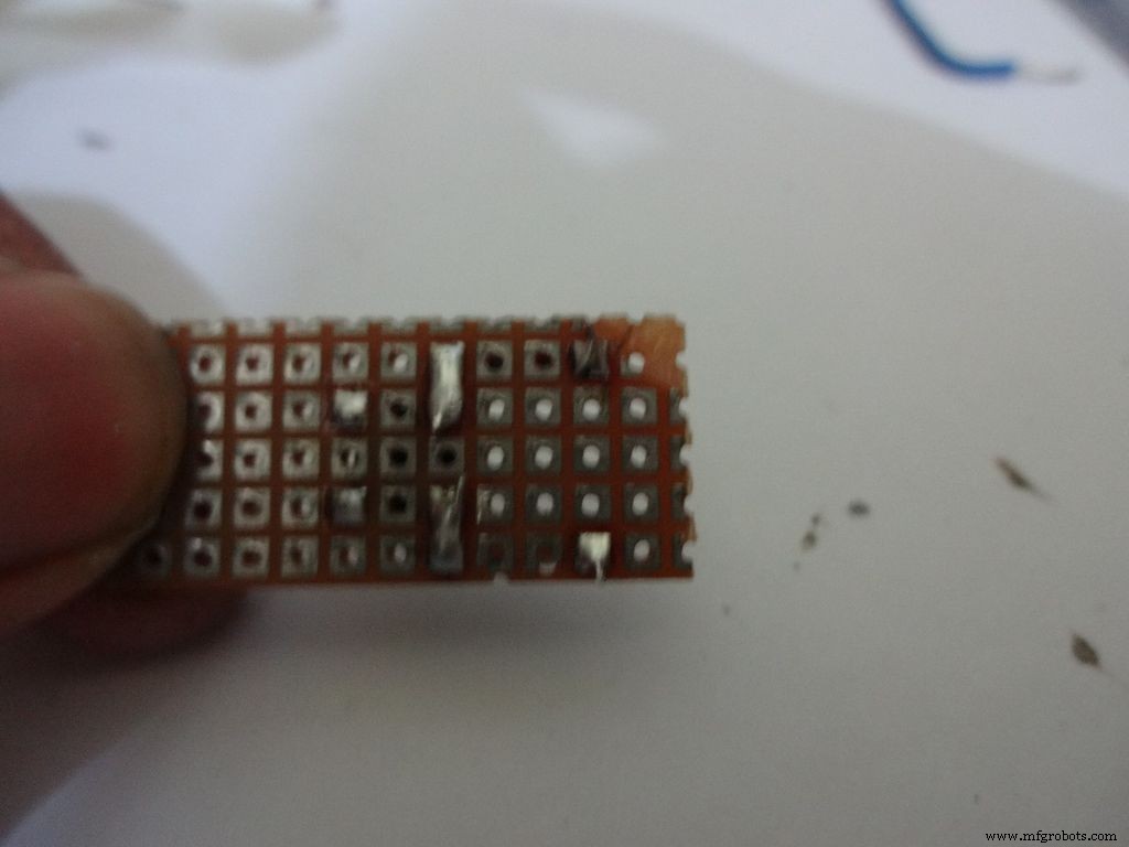
Cut a piece of General purpose PCB (10-11)dots x 5dots. Plug in and solder the pushbutton, 220 and 10k Ohm resistors as shown.
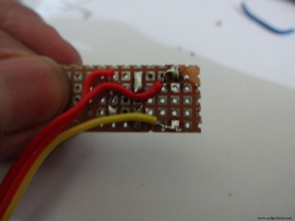
Take 3wire ribbon cable about 15cm long. Tin the ends and solder it as shown. Note down which colour wire goes to where, this will be helpful later on.
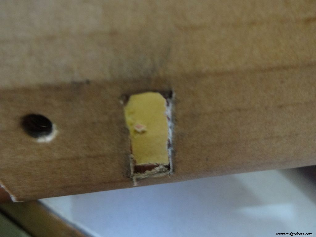
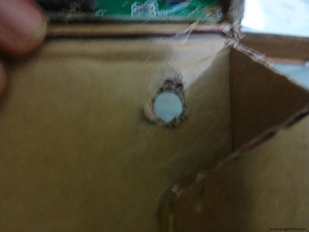
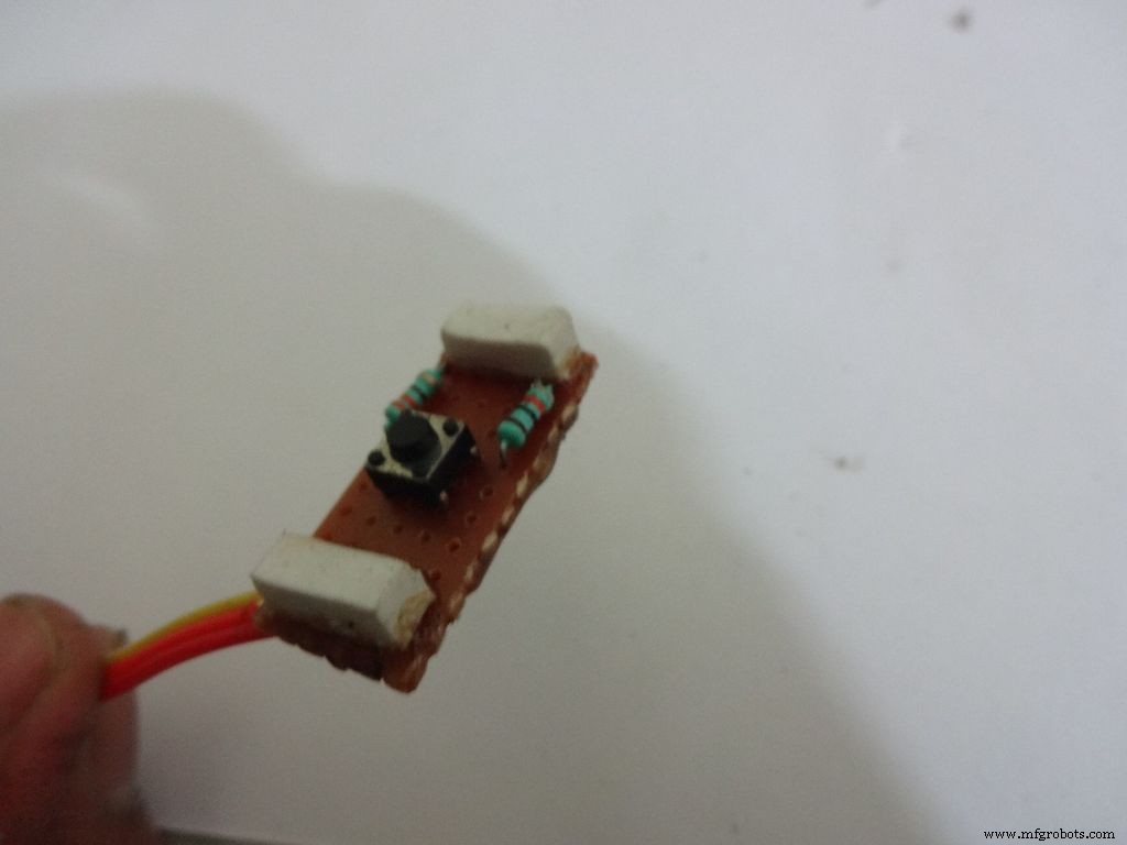
Cut 2 small pieces of eraser and place it on the ends on the board. The height of the eraser should be such that the button is below the cardboard inner level as viewed from outside. I used 4mm.
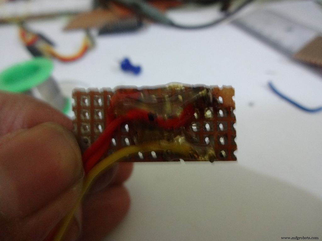
Secure it with hot glue as shown
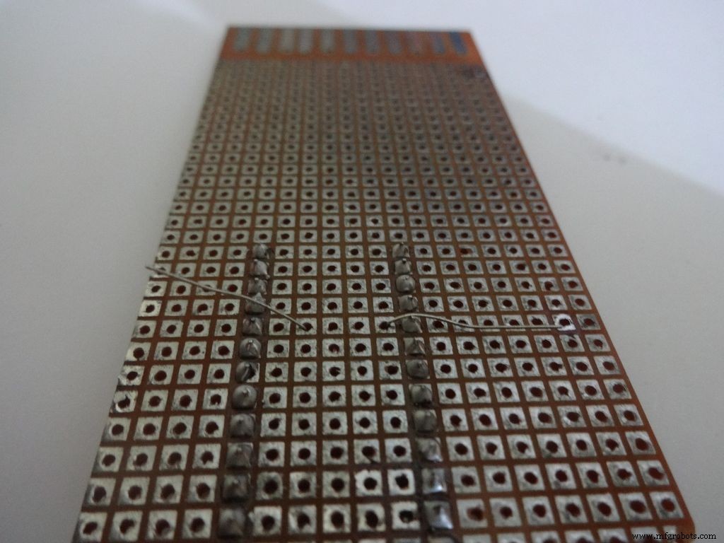
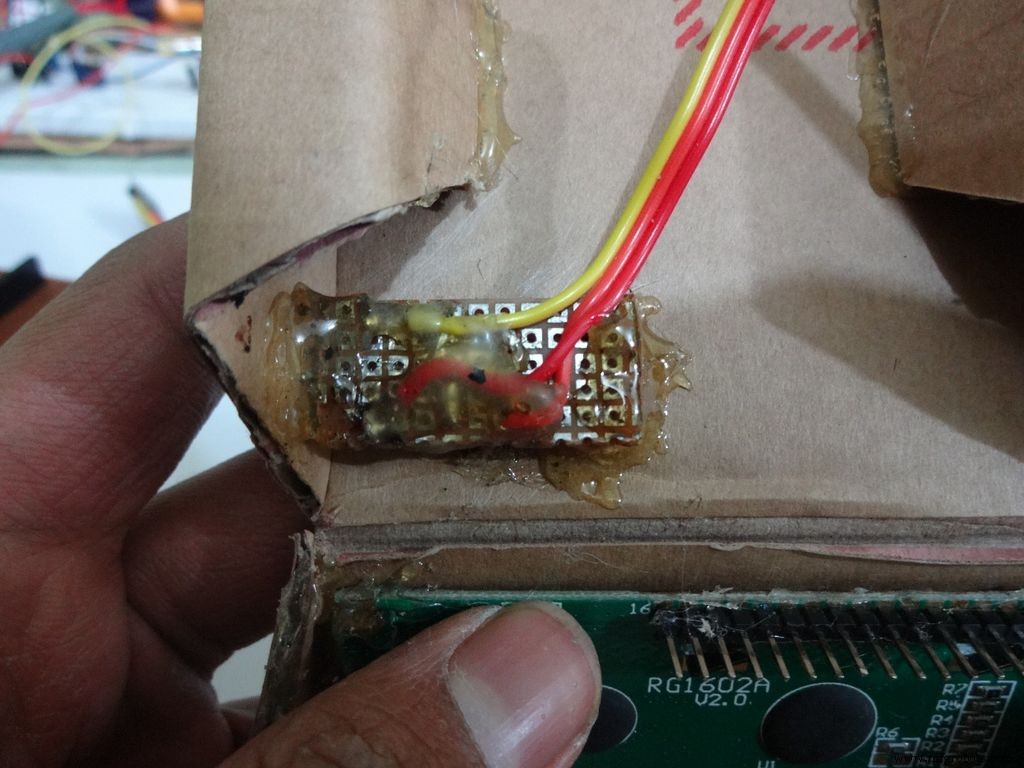
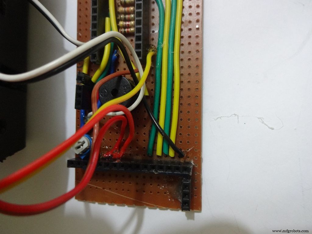
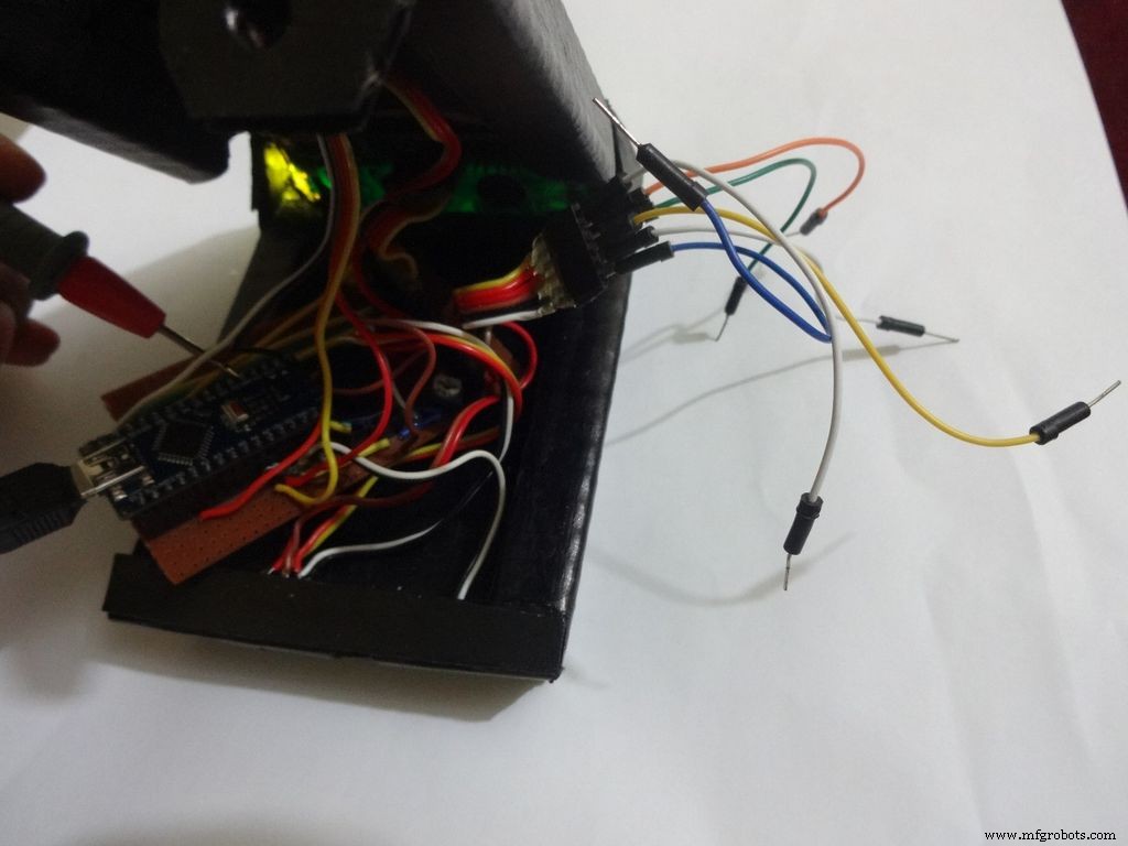
Step 22:Making the Case -- Testing points
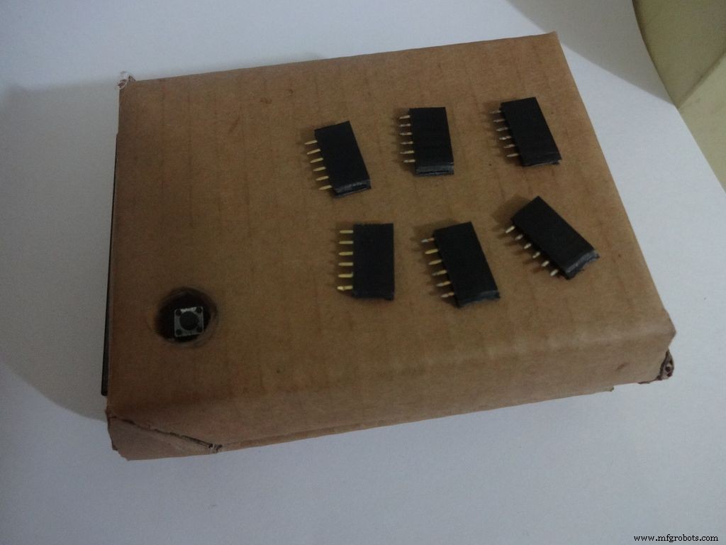
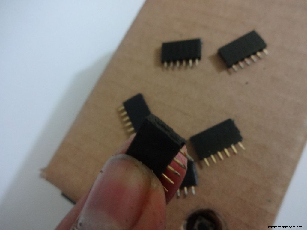
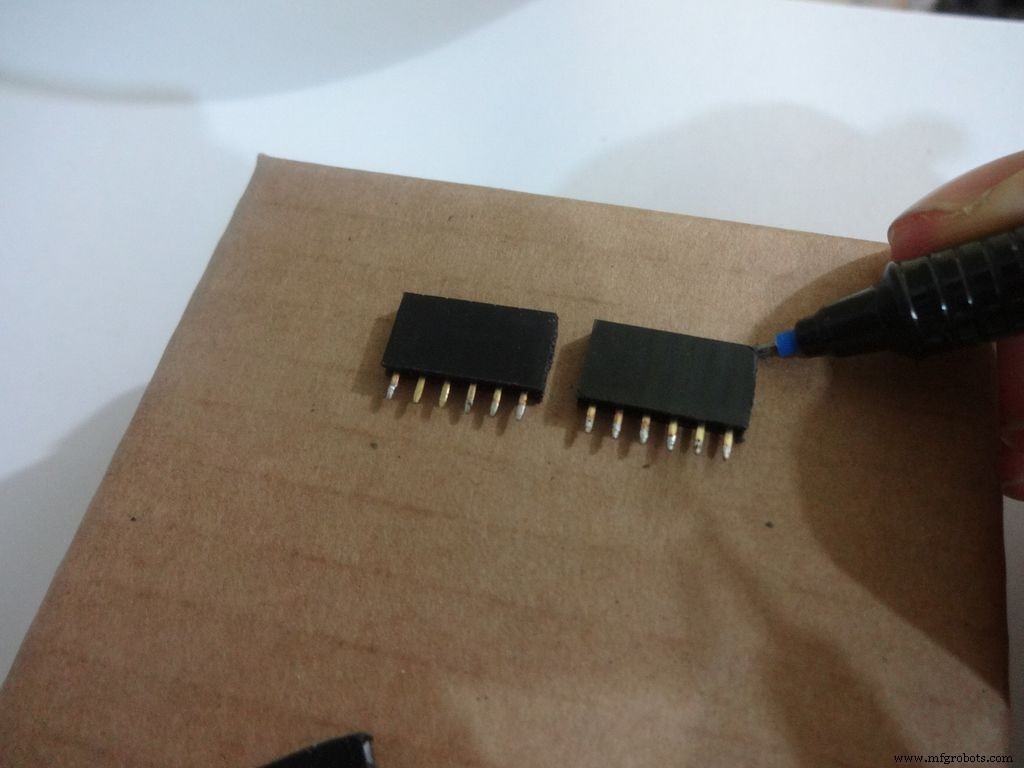
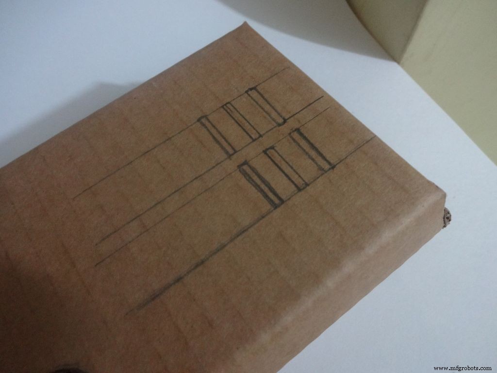
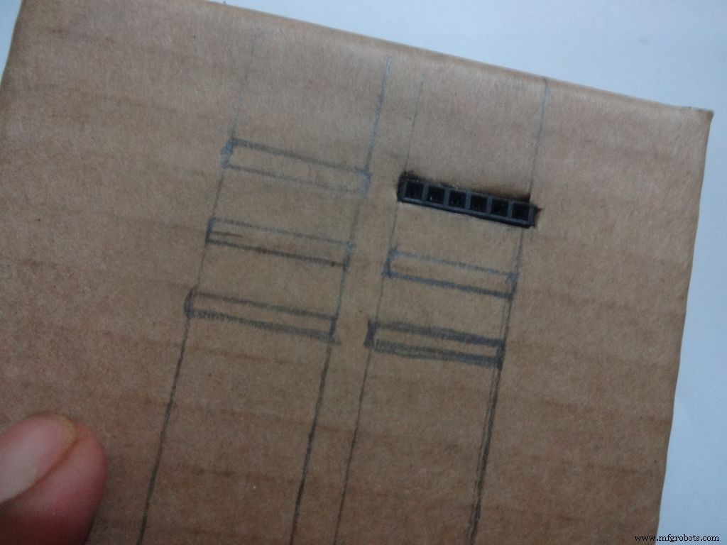
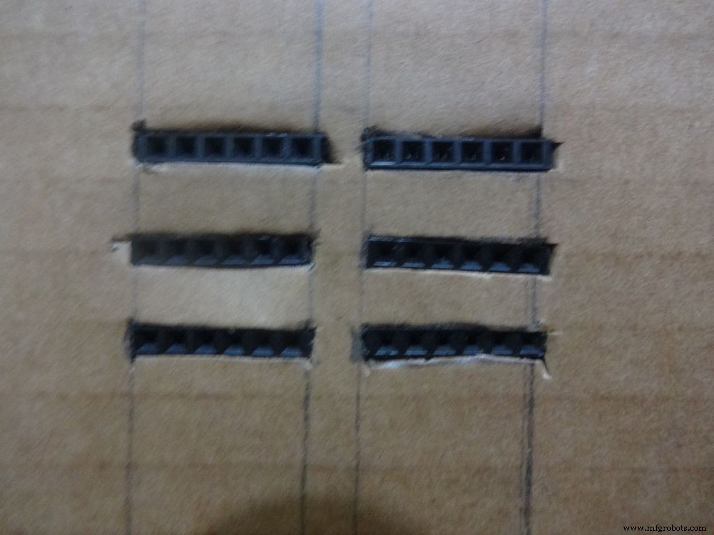
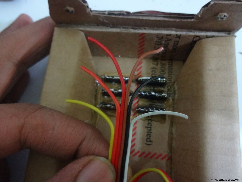
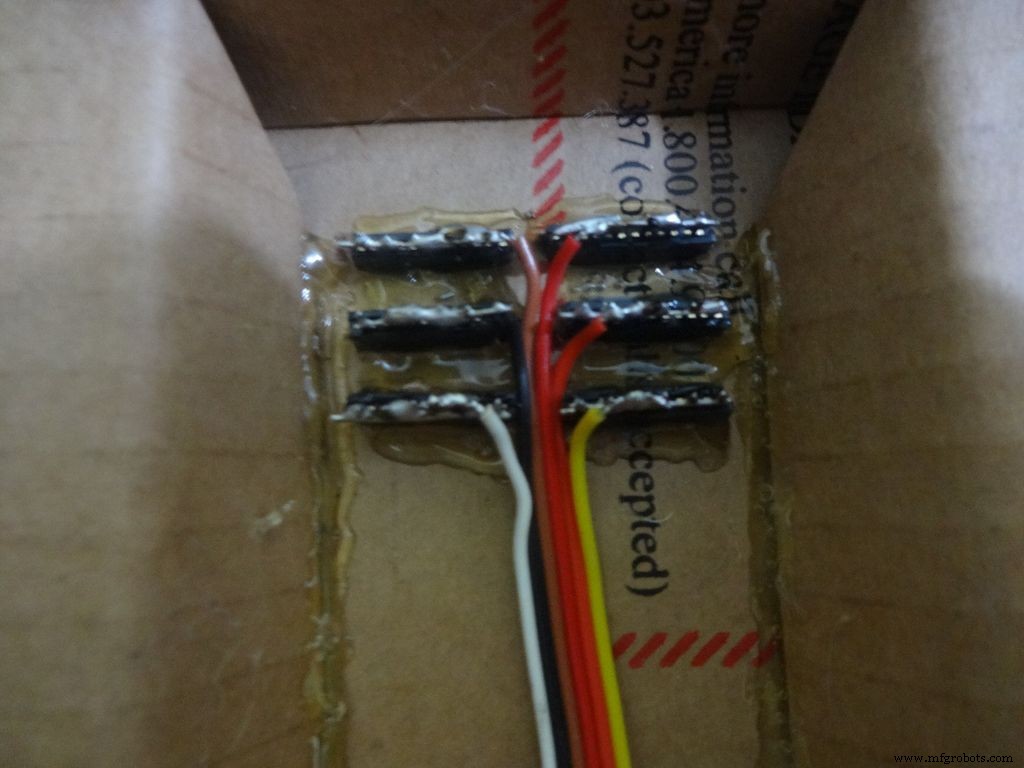
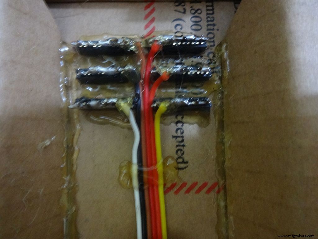
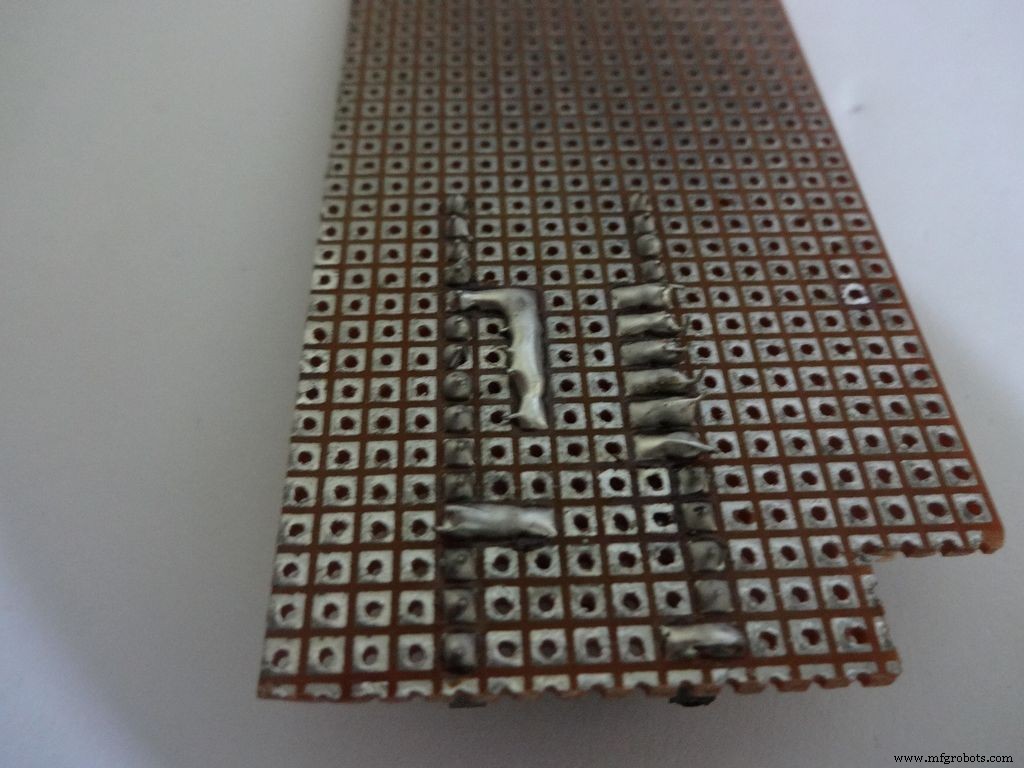
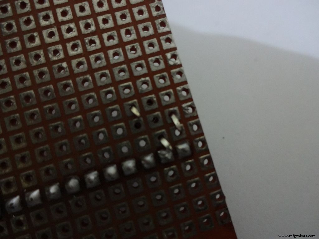
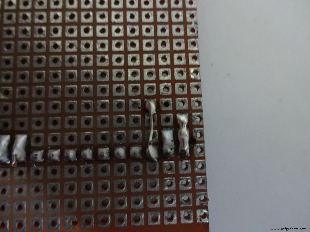
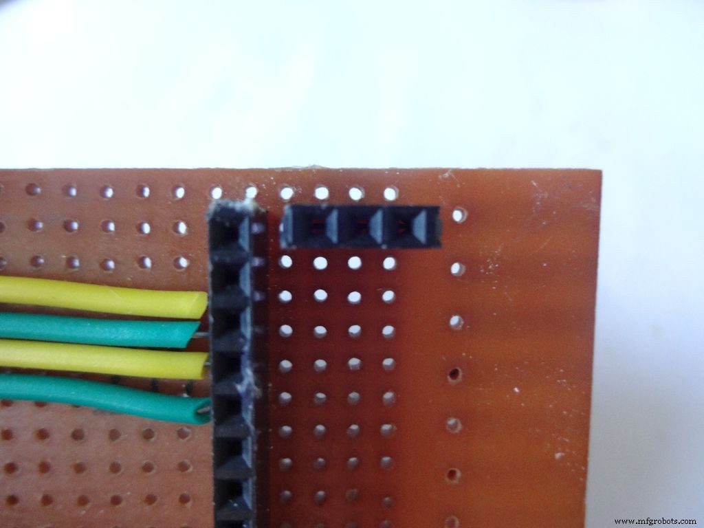
Cut 6x 6pin female header pins. Sand the sides to make it smooth.
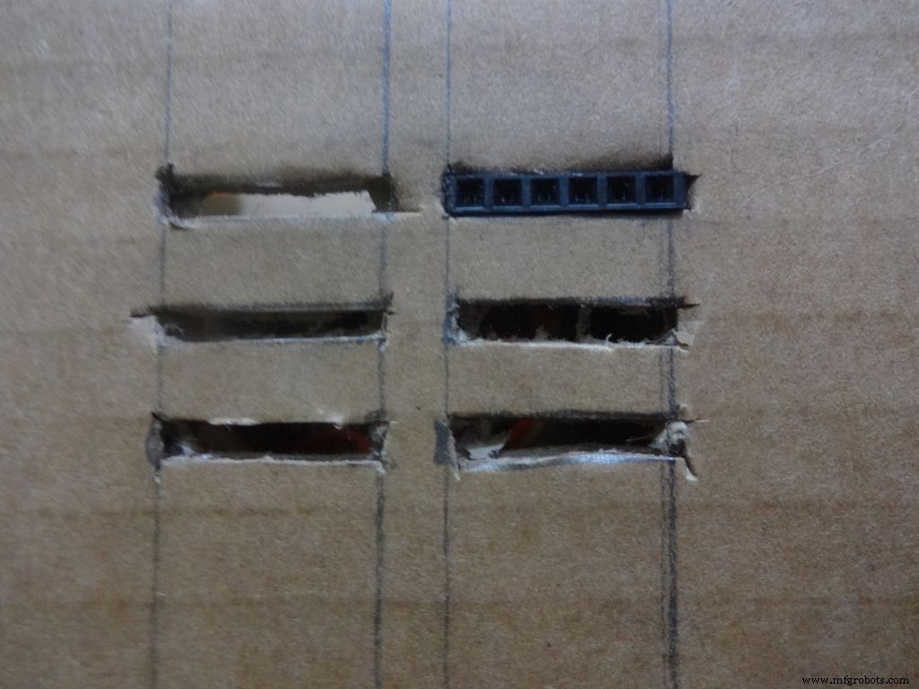
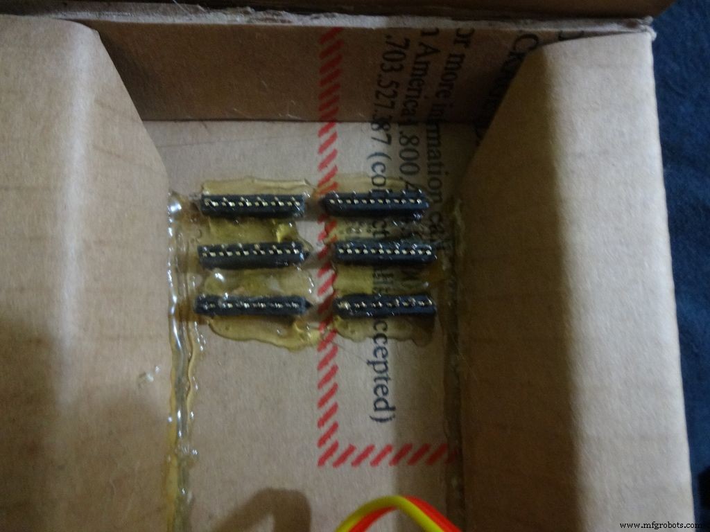
Mark the positions and cut slots for the header pins. Insert it in place and glue it from the inside.
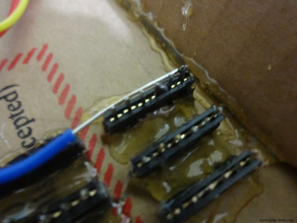
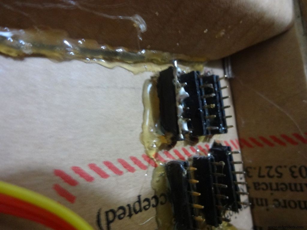
Apply small amounts of solder to all the pins and use a stripped jumper to get it all together. Make sure all of them are connected. Dont keep on heating it to make it perfect. Heating a pin also heats the neighbouring ones.
Take 6 stranded ribbon cable, tin it and attach it to each slot. Note that I put dark colours to the negative side. Apply hot glue to fix them in place.
Step 23:The Legs


Download "Legs_A4.pdf" or ""Legs_ANSI_A.pdf", based of paper size available in your region. attached at the end.
Print it on an A4 size paper (21 x 29.7cm or 8.27 x 11.69 inches) or the US-alternative ANSI A(8.5 x 11inches or 21.6 × 27.9cm). Make sure that while printing you select the proper paper size, orientation, and select the "Actual Size" option. Confirm that the print is accurate by measuring the rectangle. It should be 8.4 x 11.8cm
Cut crease and glue it just like the main case, see the images.
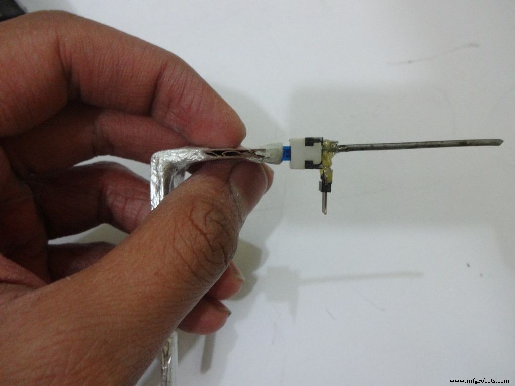
Step 24:Making it shiny!
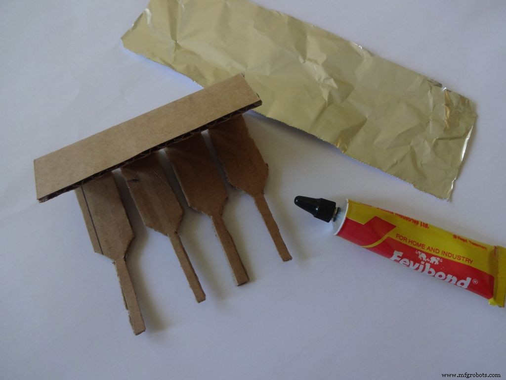
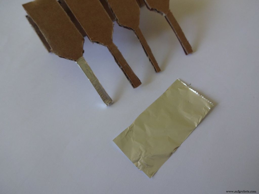
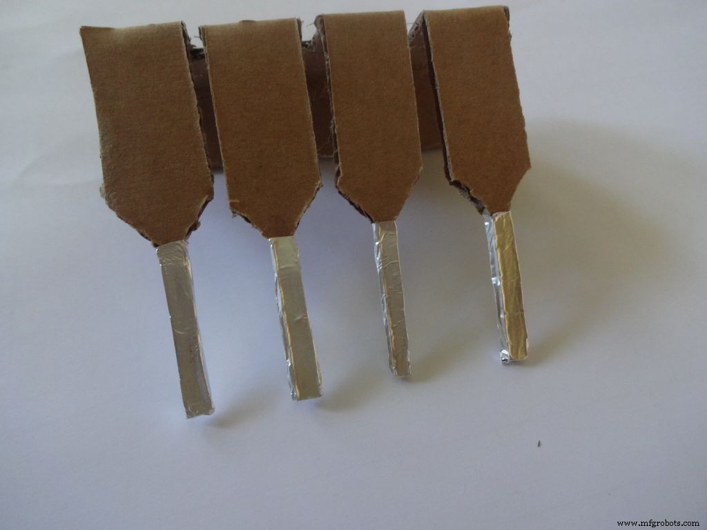
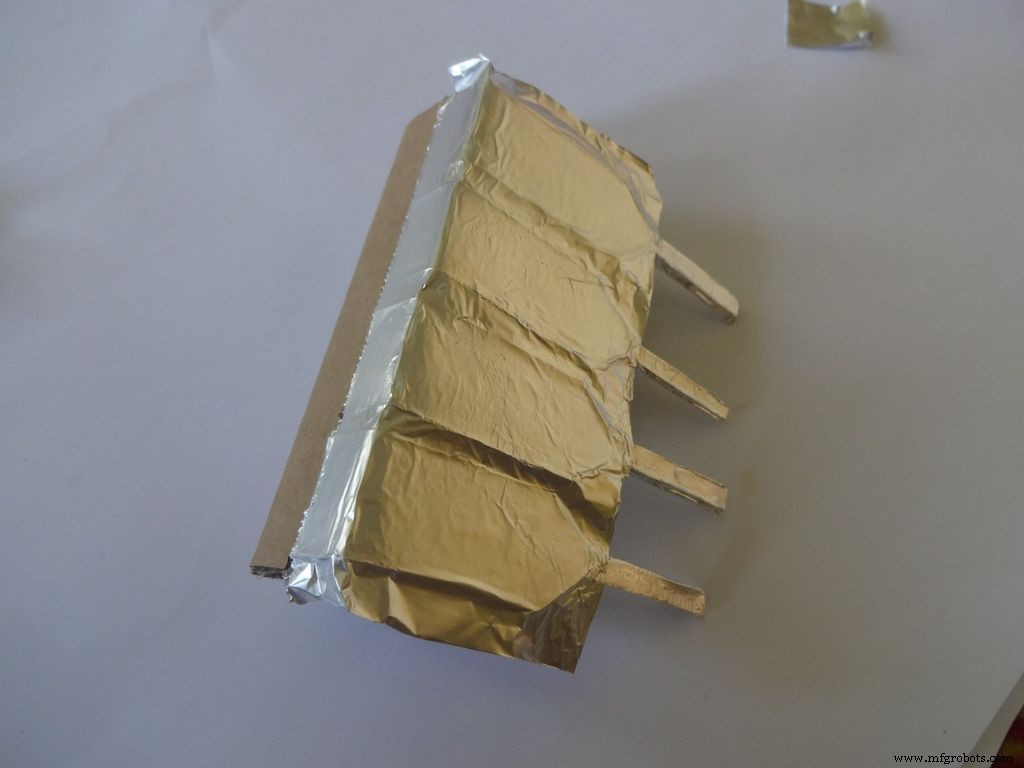
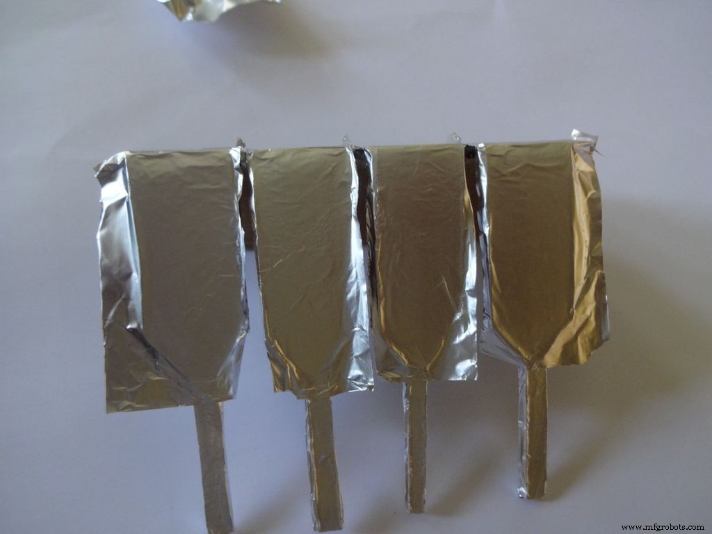
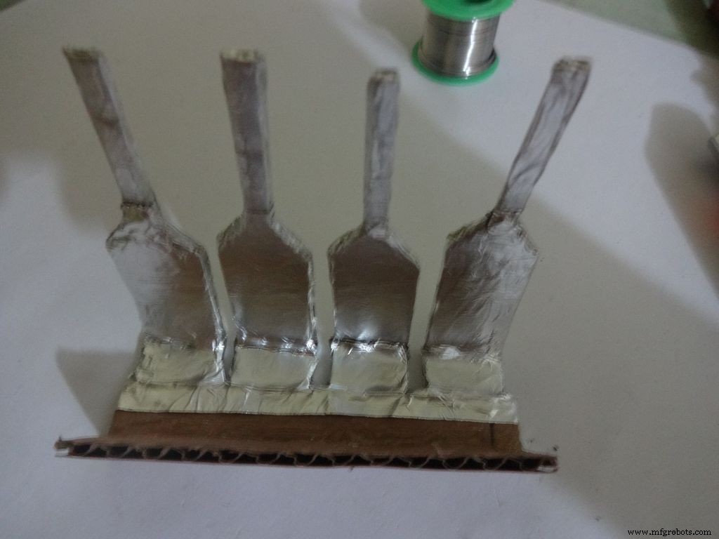
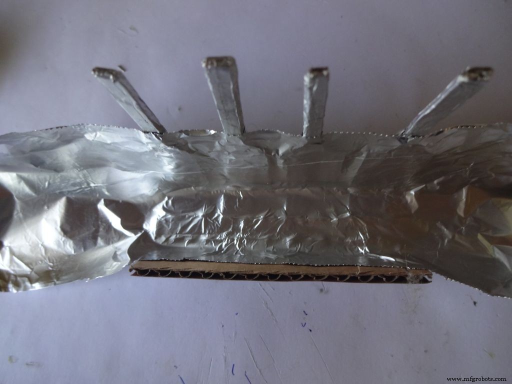
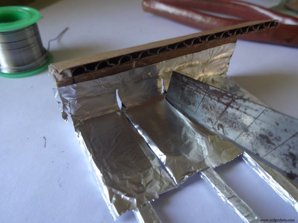
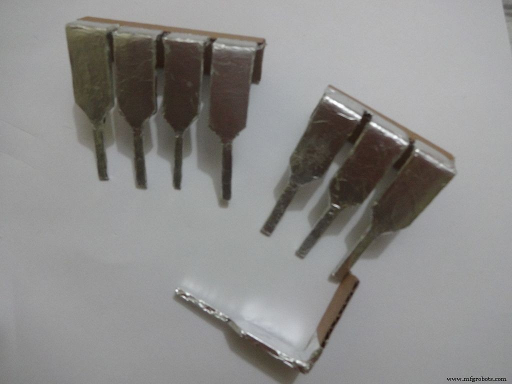

Cut a piece of foil 1x2inches and stick it carefully, fold by fold to the leg ends with some metal-cardboard sticking glue. I used Fevibond.
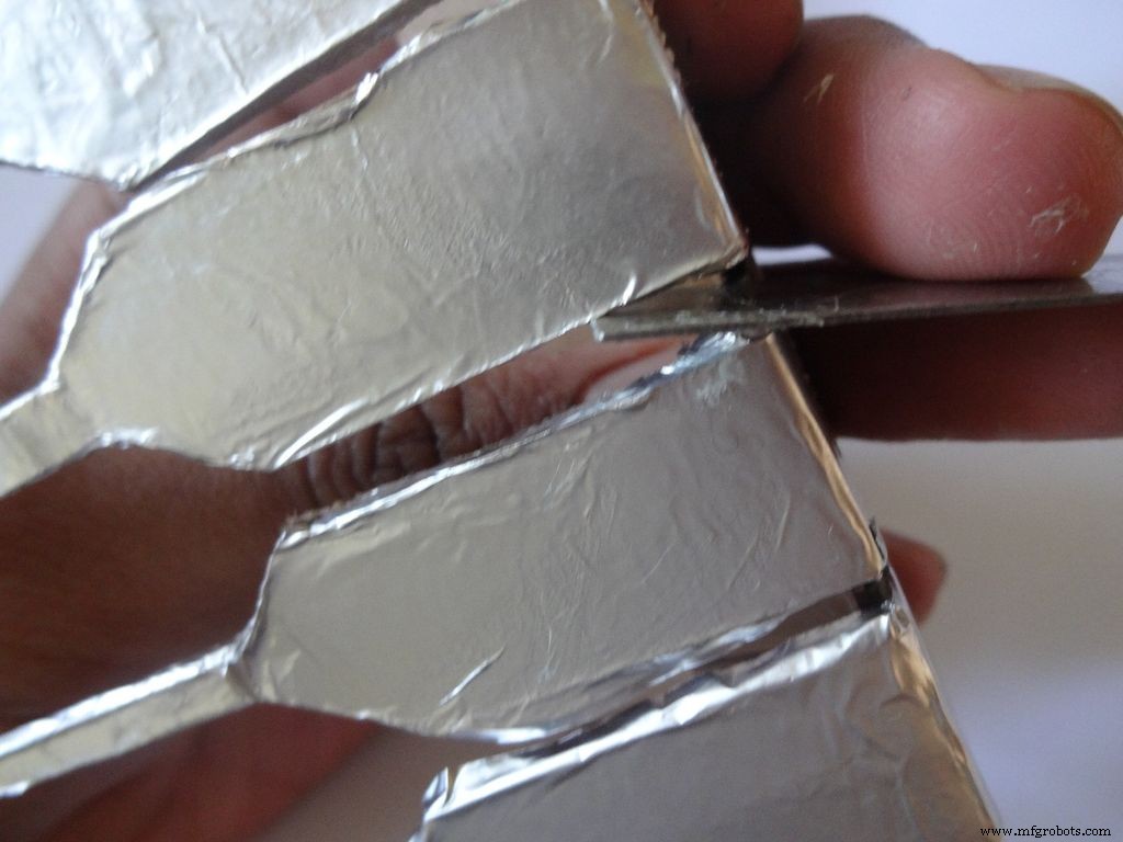
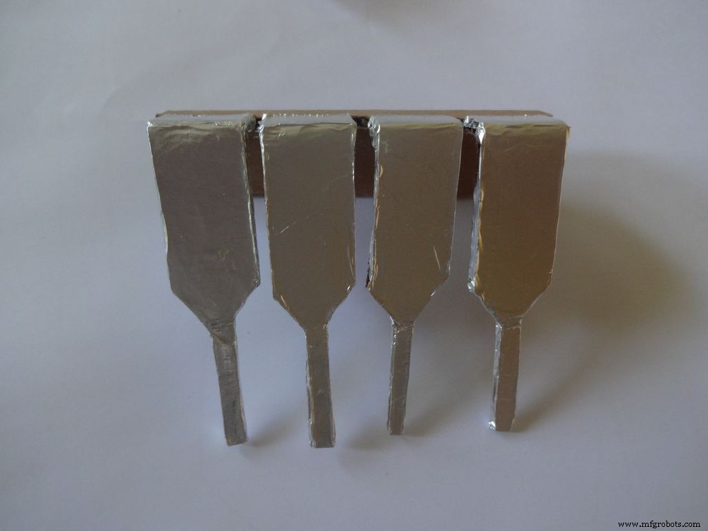
Next stick a patch that covers all the leg tops(as shown), make cuts slowly with a cutter. Do this carefully. The foil tends to tear to the sides. Use something flat to stick the foil in between the legs and give it a good finish.
Now cover it with transparent cello tape, just like you applied the foil, to protect it from sharp objects.
Step 25:The Power Switch
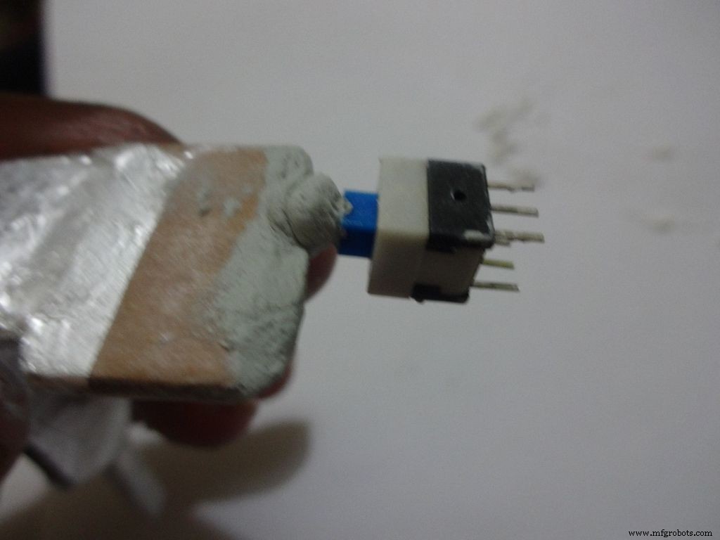
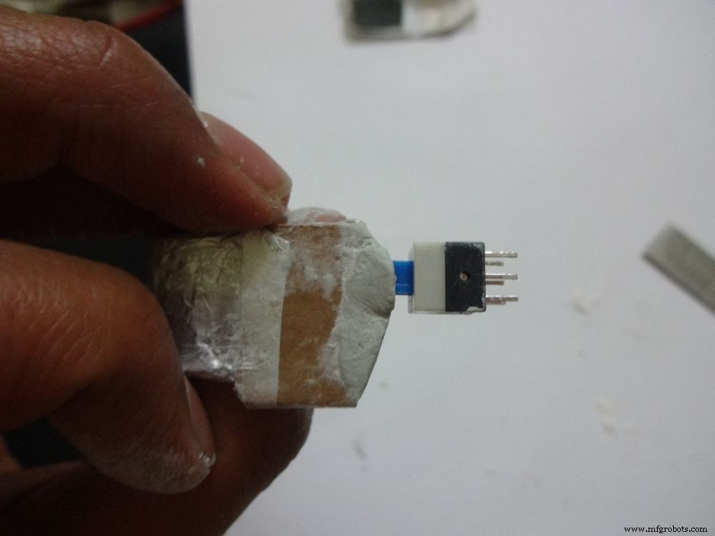
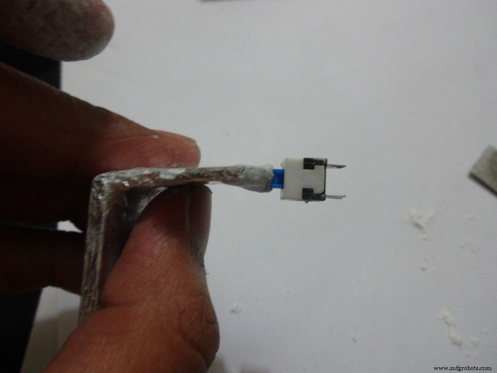
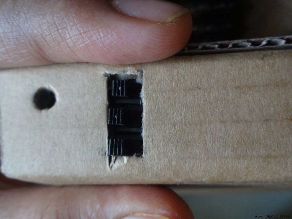
Measure and cut the power switch leg by properly keeping it in place. Temporarily stick the other pins with tape to get the pin1 position right.
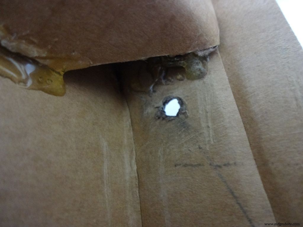
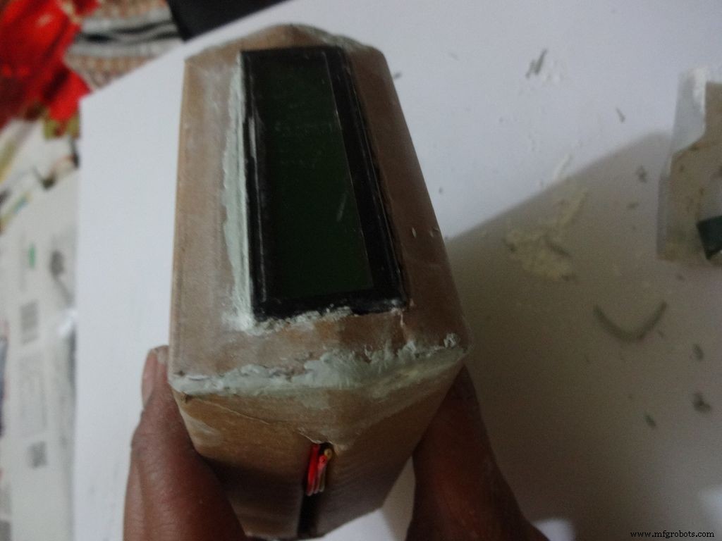
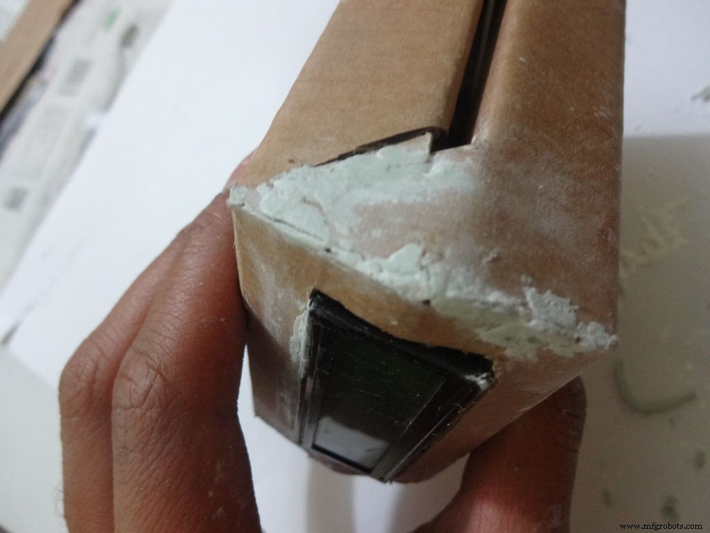
Mix the m-seal(epoxy putty sealant, gets very hard when it dries) well. Put it as shown in the images and use powder+flat surface to shape it. Let it dry.
Also fill any gaps left in your case.
Note:We cant use hot glue here as it is rubbery and the switch needs to be stuck with some strong brittle material.
Step 26:Power switch to PCB

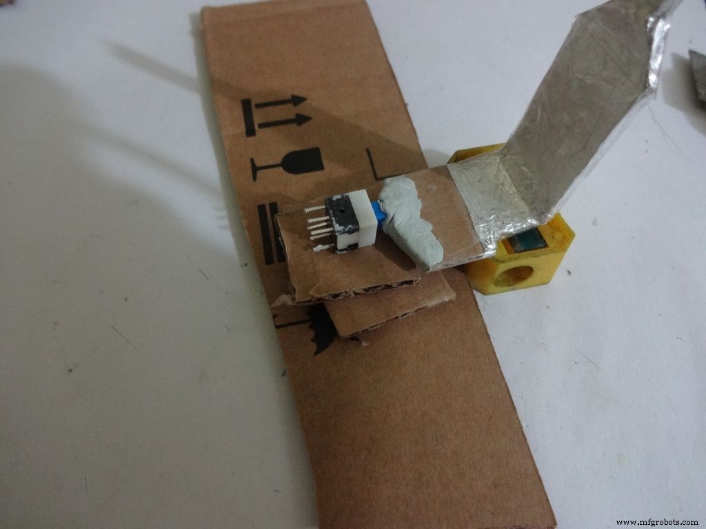
After The m-seal dries, place it in to check if everythings alright.
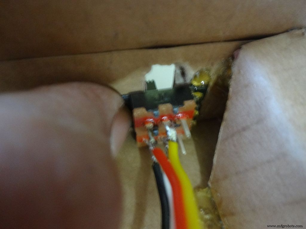
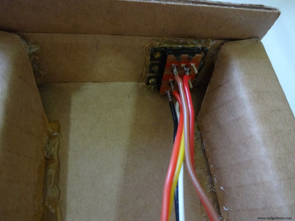
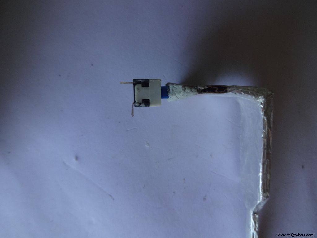
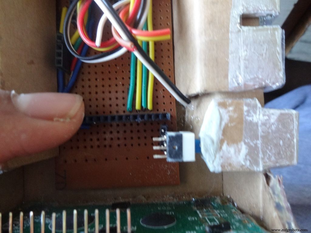
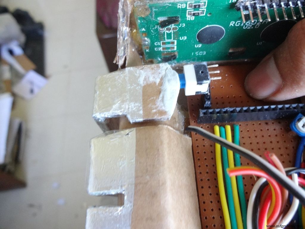
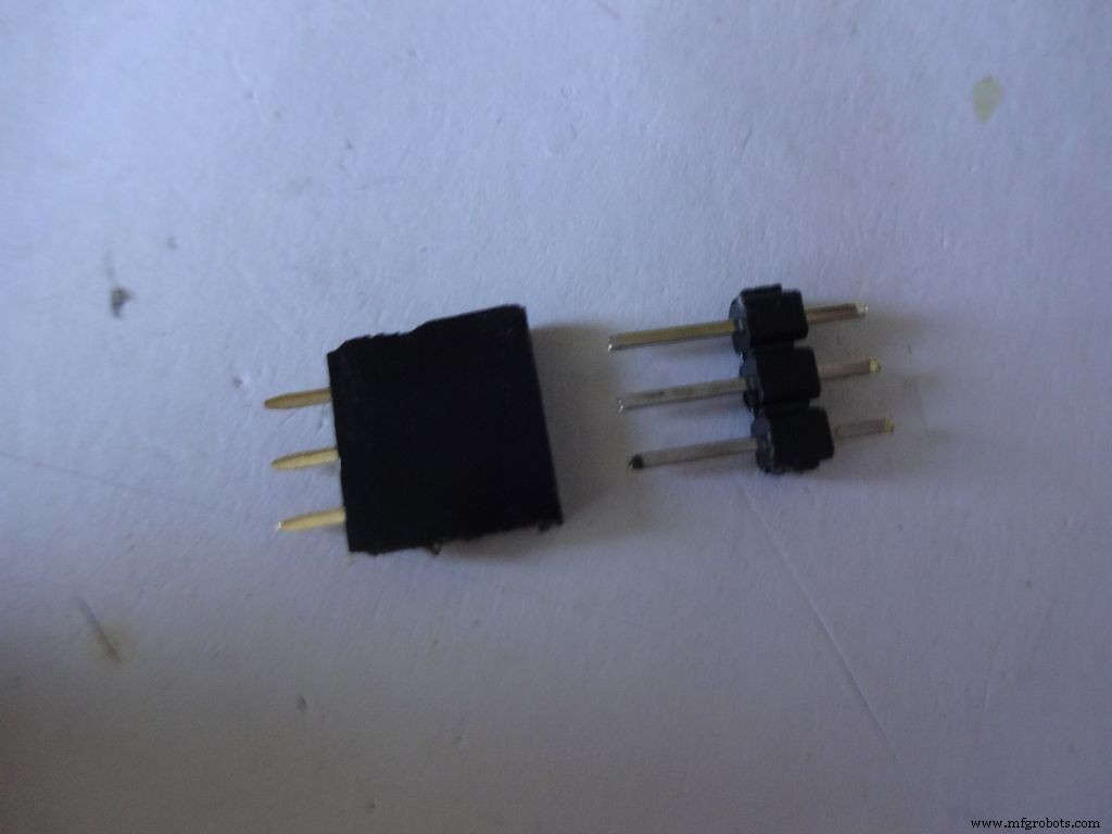
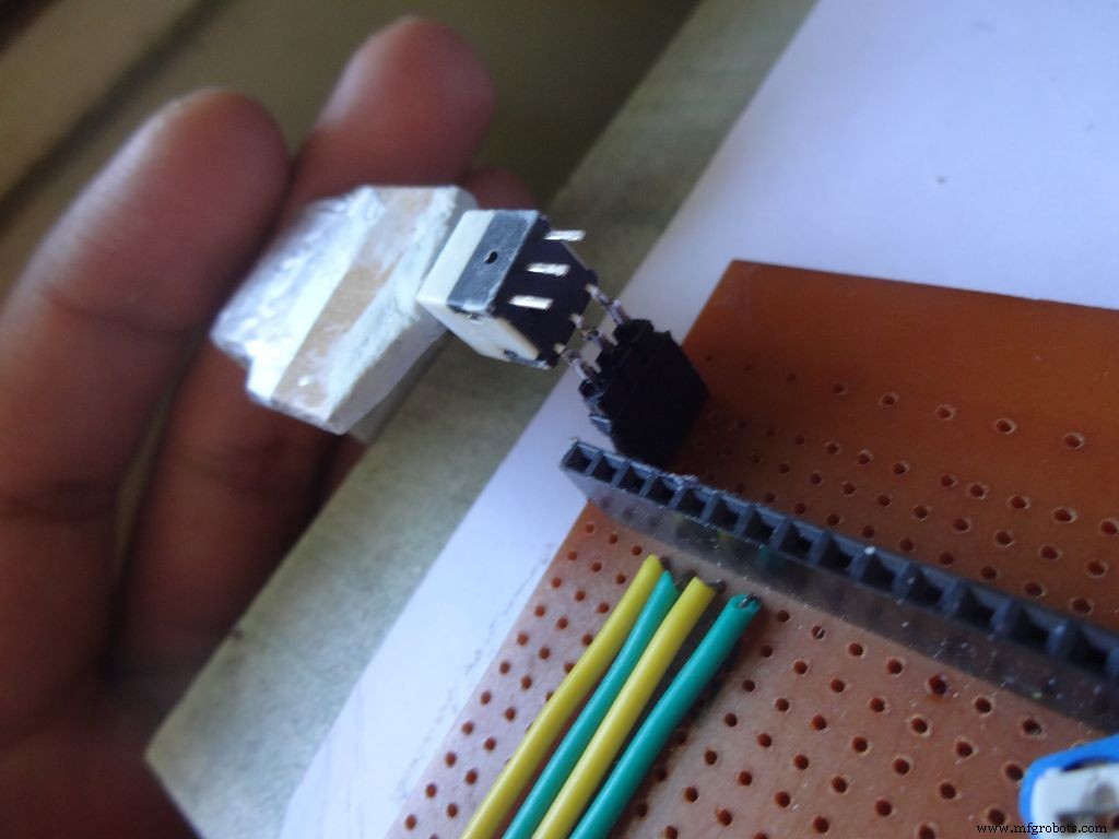
Cut 3pins of female and male headers place it on the PCB such that it aligns with the switch pins. Solder the female part.
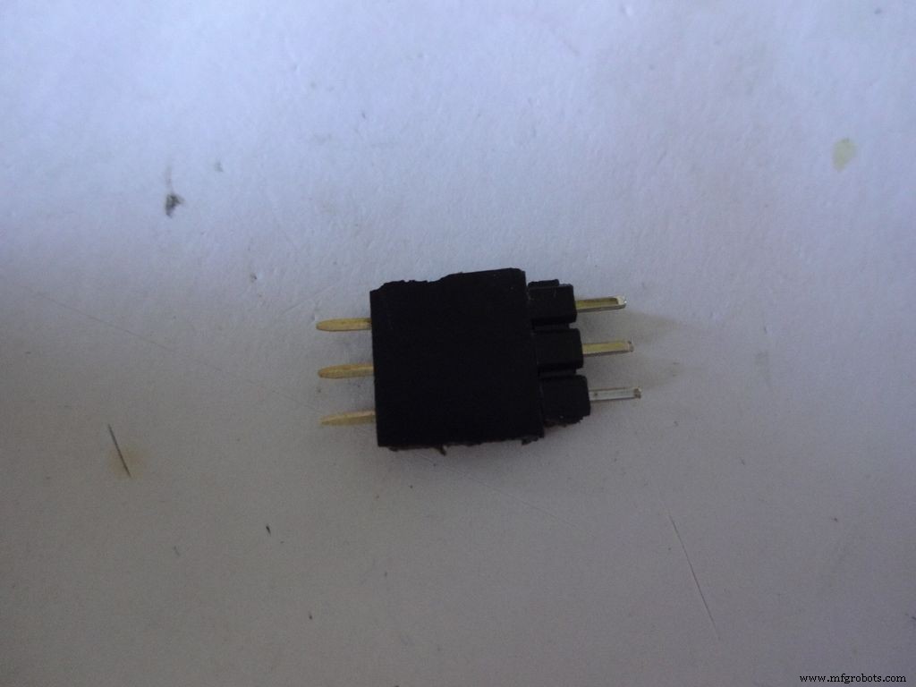
Tin the switch leads and the male header pins, join them. See if it fits at the right place.
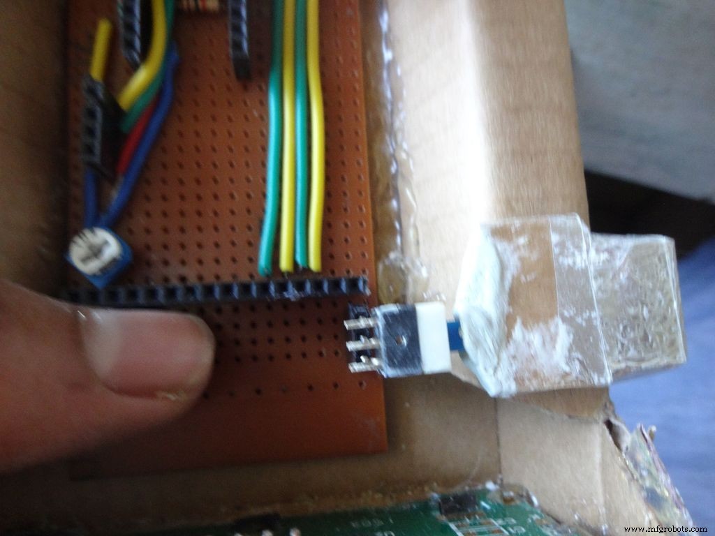
Try pushing the switch on and off after placing a finger behind the switch for support. We will add a support rod later on.
Connect a side pin of female header(power switch) to Vin. I realised this late and had to undergo lots of trouble.
Secure the header Pin with hot glue.
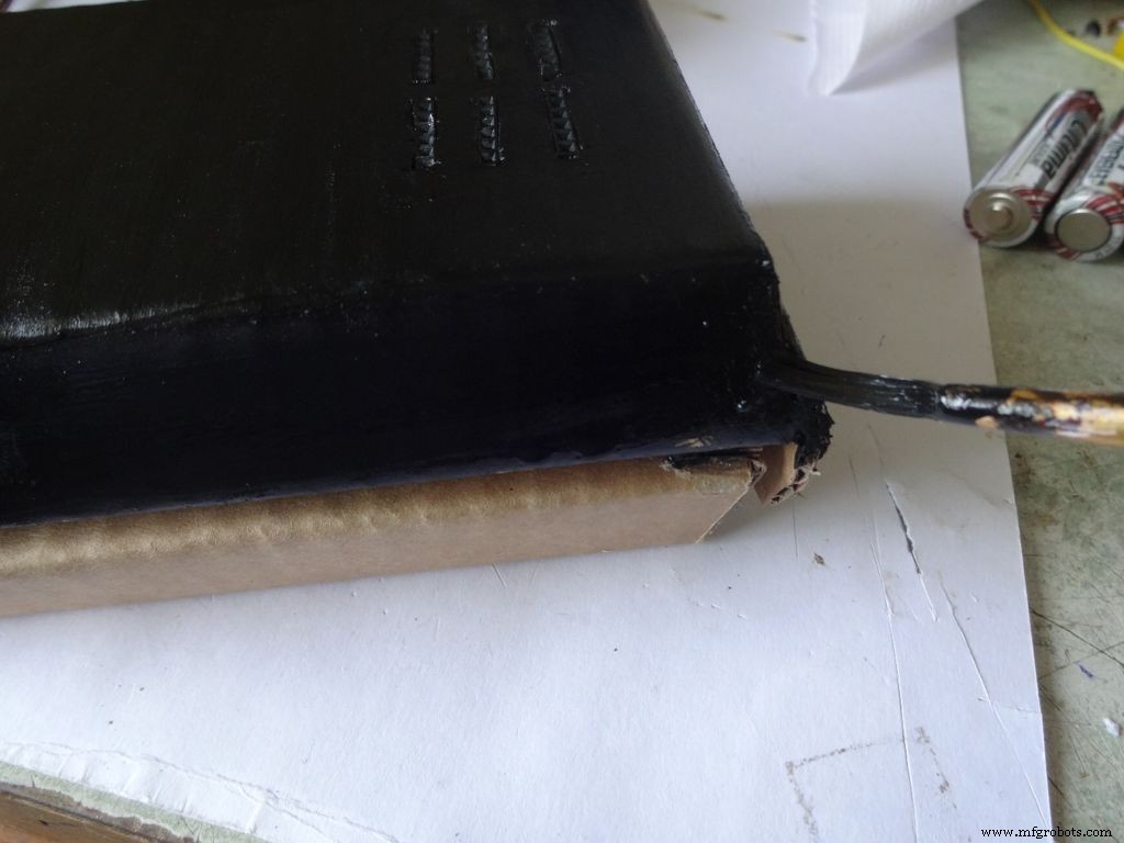
Step 27:Making the USB Port

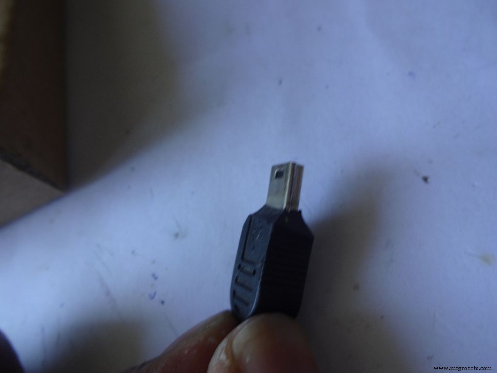
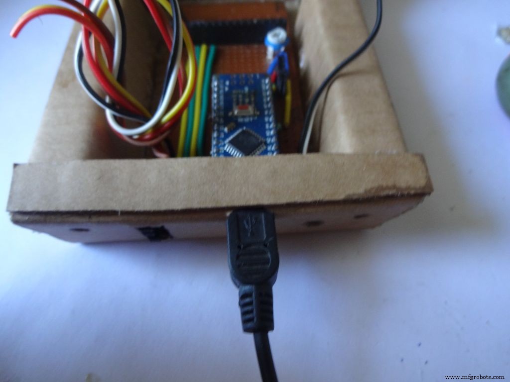
Put the PCB properly in (with Arduino) and cut a rectangle for the mini USB port.
Remove some plastic from the USB cable so that it fits the Arduino properly. Test whether connection is proper.
Step 28:Some other things...

I removed all the LEDs from the Arduino Nano and also the power LED on my RTC module. These consume unnecessary power, which matters if you are operating on a battery.
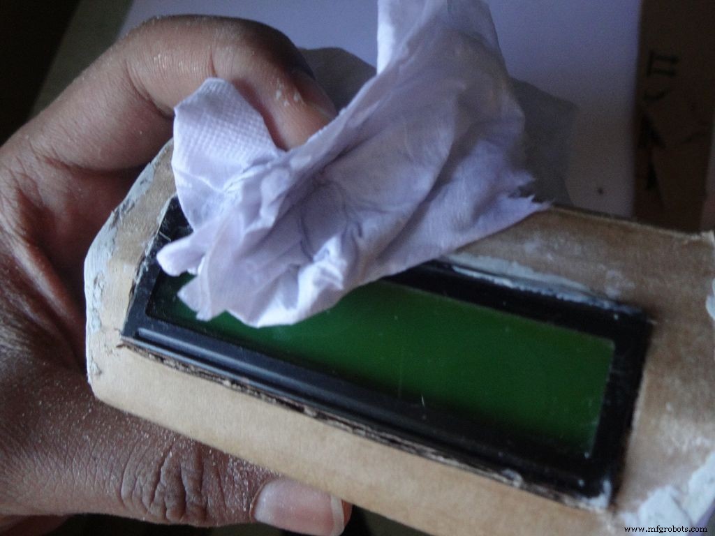
Sand the dried m-seal so that it mixes smoothly with the cardboard. Clean the powder with a wet paper napkin before painting.
I also added a buzzer which may be used for some functions. Buzzers are sensitive, don't use too much heat while soldering!
Step 29:Time to paint!
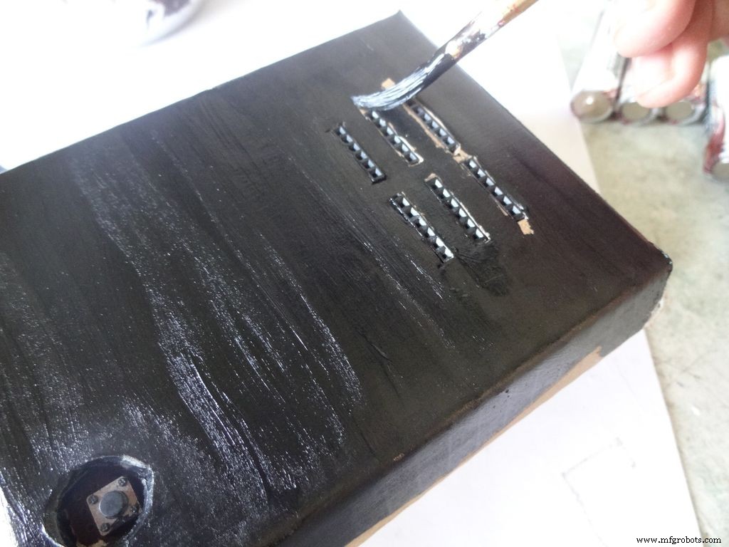
Dont use direct thick paint while painting, this cases brush patterns to appear. Use sufficient water.
Make sure no tiny bubbles are formed. These form when you dab the brush too much.
Dont paint the cover hinge, the paint will restrict it.
This is just a base coat. Another layer of paint will be added while finishing up.
Step 30:Soldering all the wires
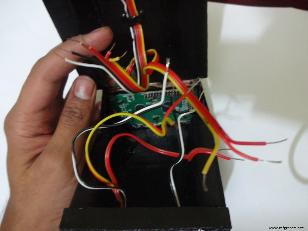
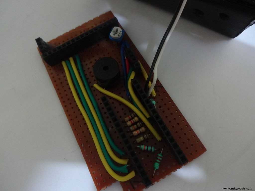
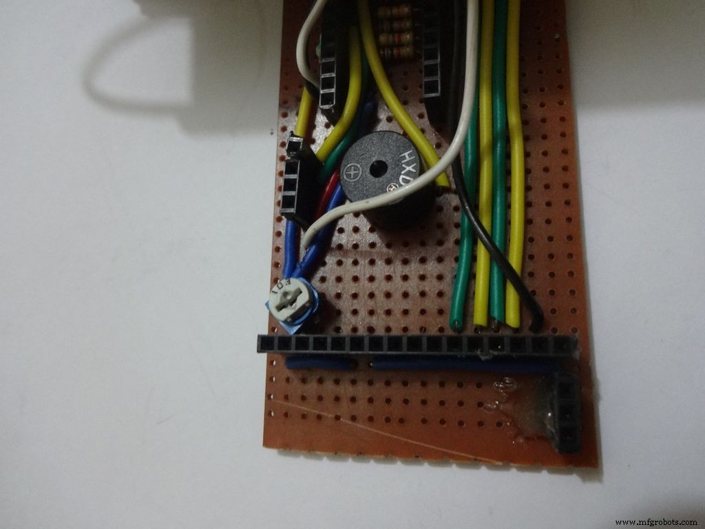
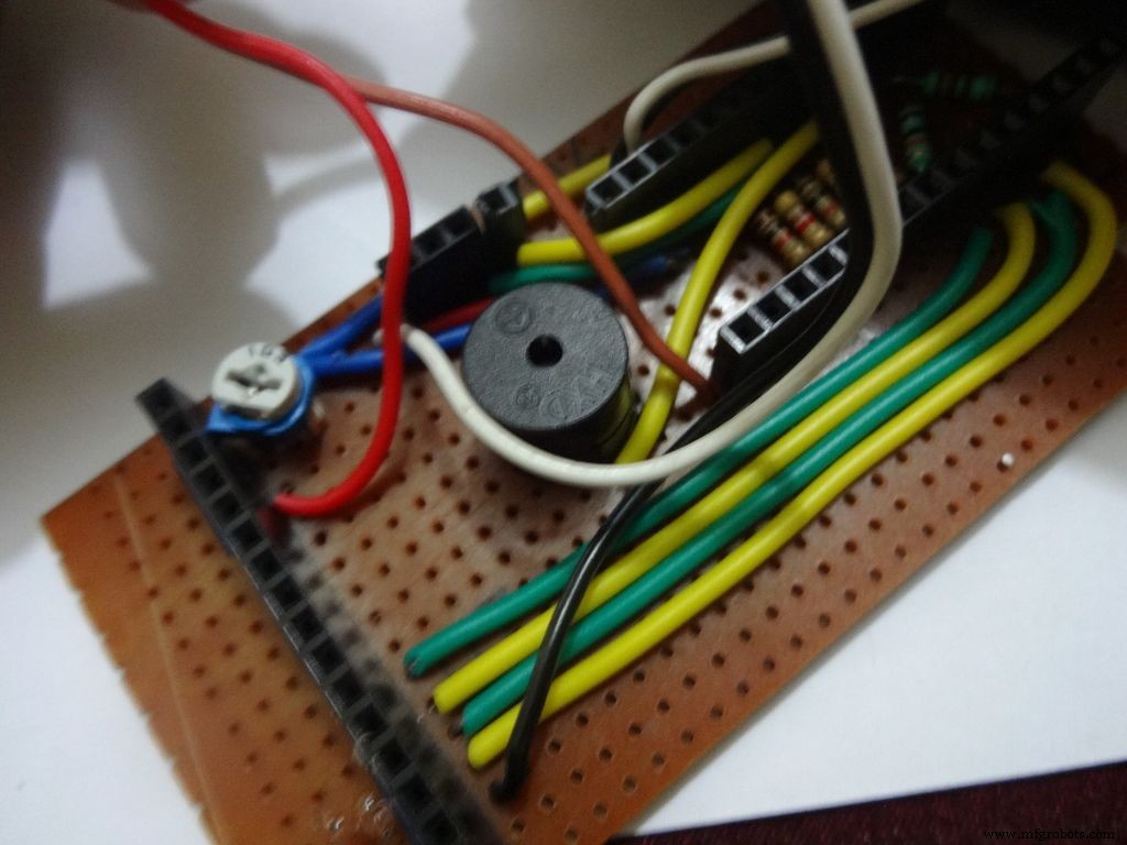
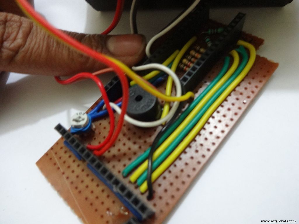
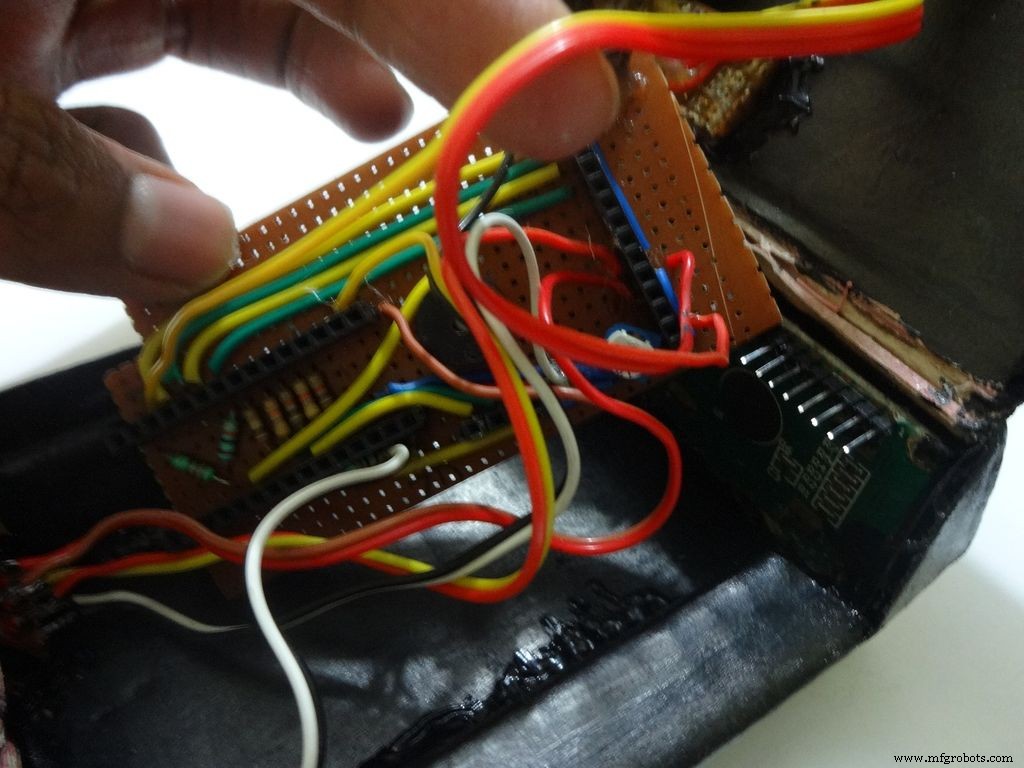
Make sure you refer the circuit design before making any connections.
First connect the reset switch, one end to RST and one end to GND.
Then, the backlight switch. One end to +5V and other end to 'A' or Anode of the backlight LED. Also connect 'K', Cathode to GND.
Next is the RS switch, connect one end to RS and other to pin D1(TX).
And finally the Enable switch. Connect one end to 'E' or Enable and other end to pin D0(RX).
Switches
Where to?
Reset - pushbutton RST and GND Backlight - slide +5V and A RS - slide D1 (TX) and RS Enable - slide D0 (RX) and E
Note:Pins D0 and D1 are connected through switches as keeping them connected sometimes causes problems while using Serial(for debugging).
This completes the base wiring. Apply hot glue after double checking the connections.
Then connect the 3 wires of mode change button:The 10k pulldown resistor to GND. 220 Ohm resistor to pin D11 and input pin to +5V or VCC
Finally connect the 6 wires from the test slots to their appropriate places(shown in images).
Positive
Negative
Resistance Test A7 GND Capacitance Test A0 GND Diode Test A6 D12
Note:All the +5Vs and GNDs are same and hence connect to most convinient spot.
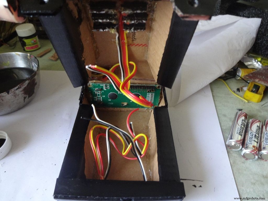
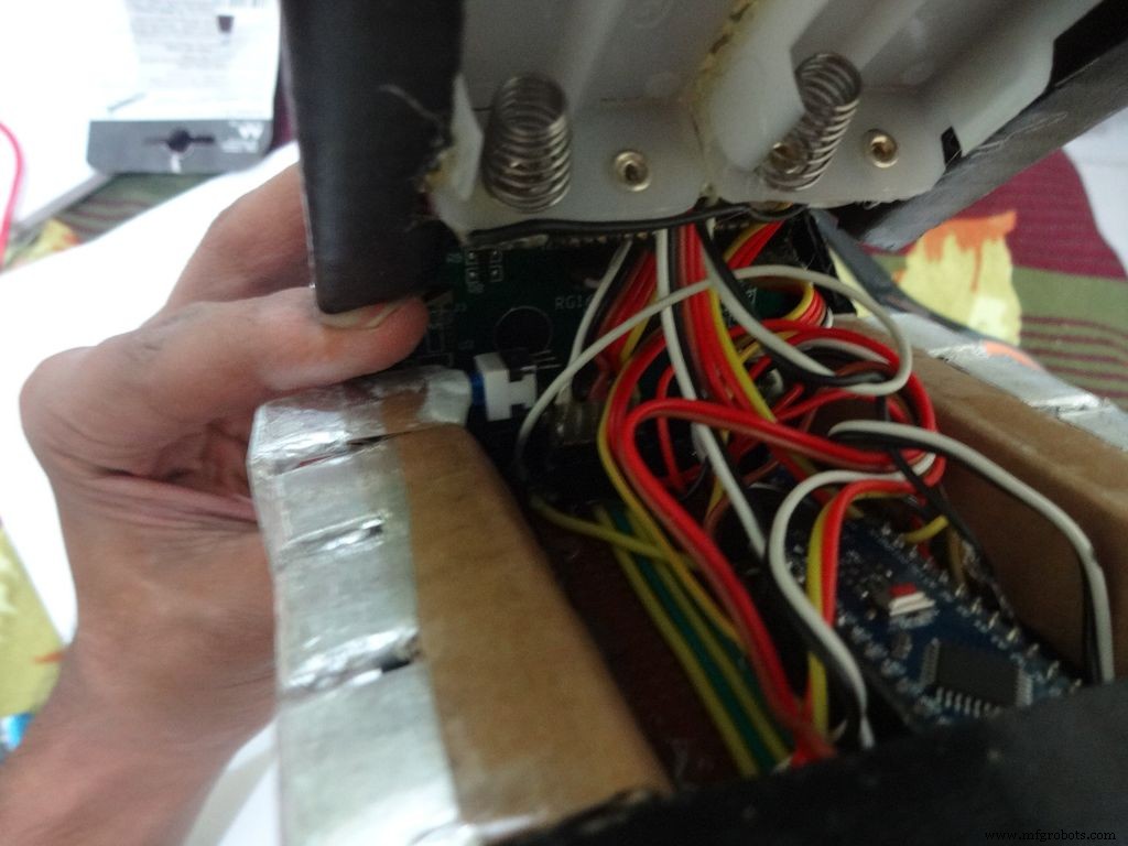
Step 31:Adding the battery case
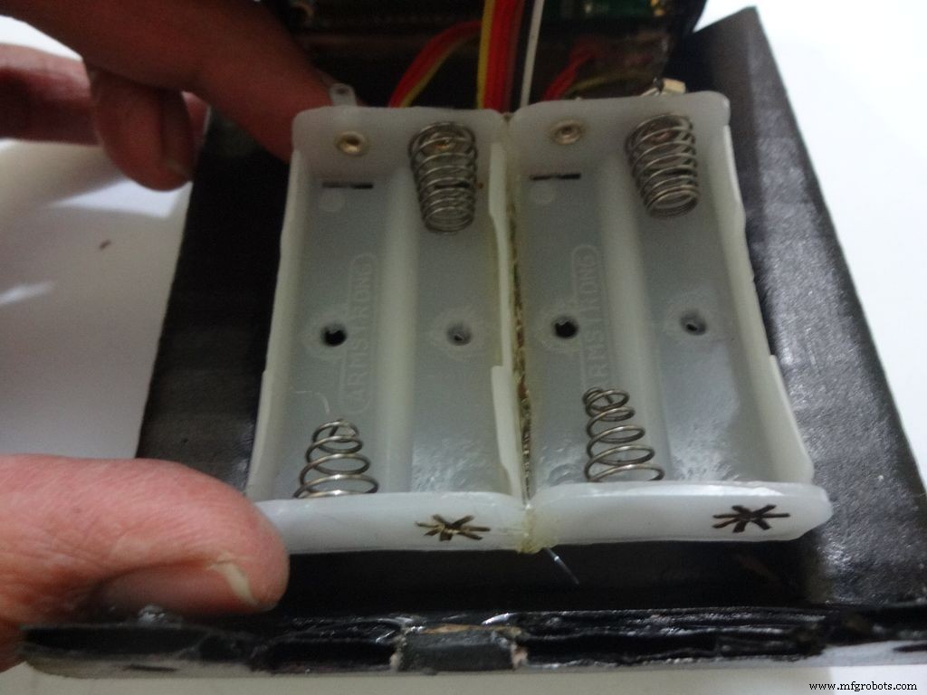
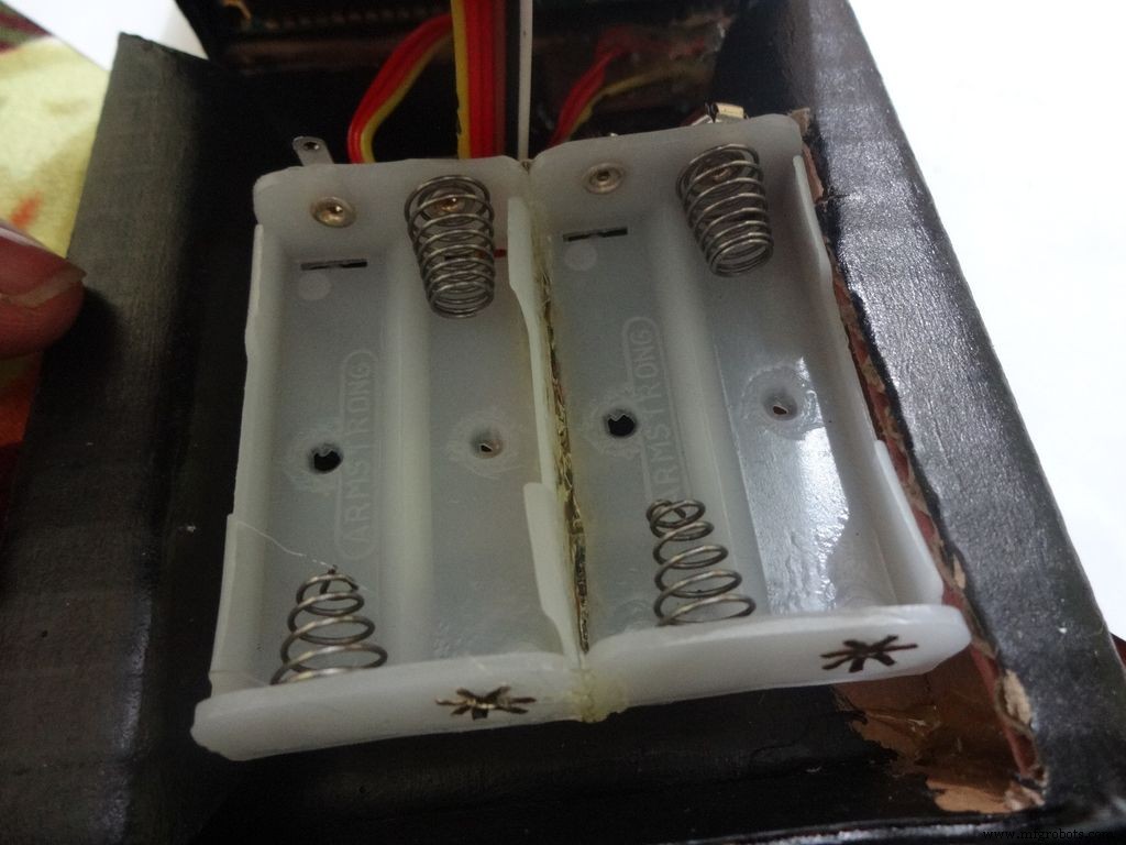

Place the battery case at the top cover, make cuts to place it inside such that the cover can be closed properly.
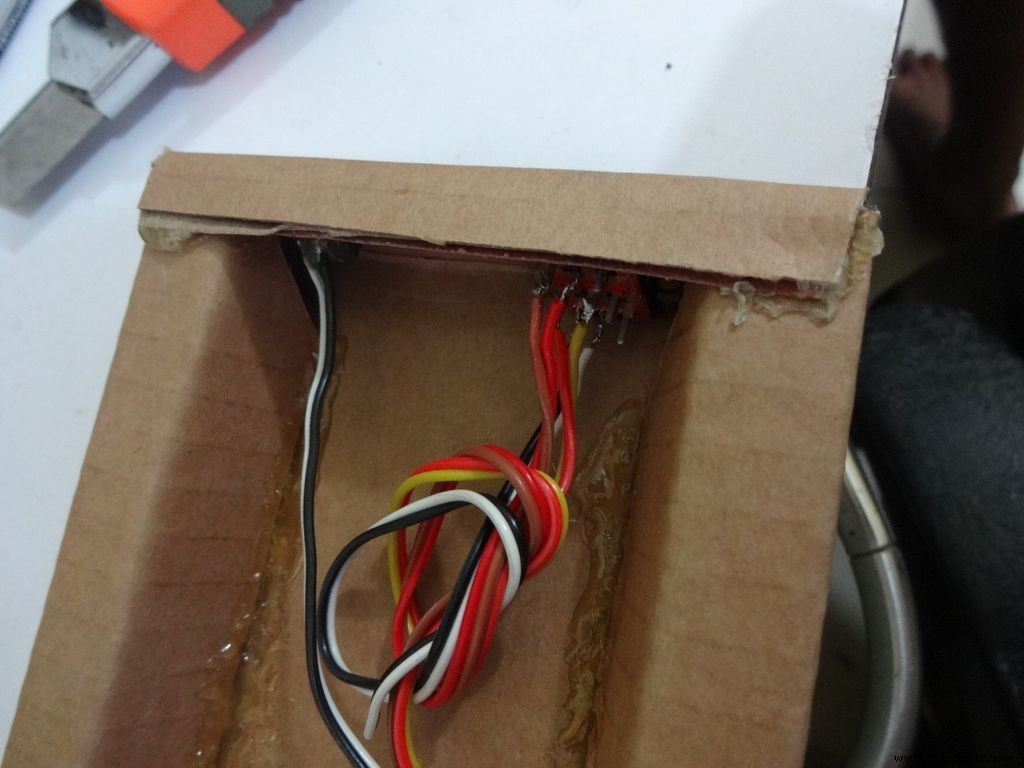
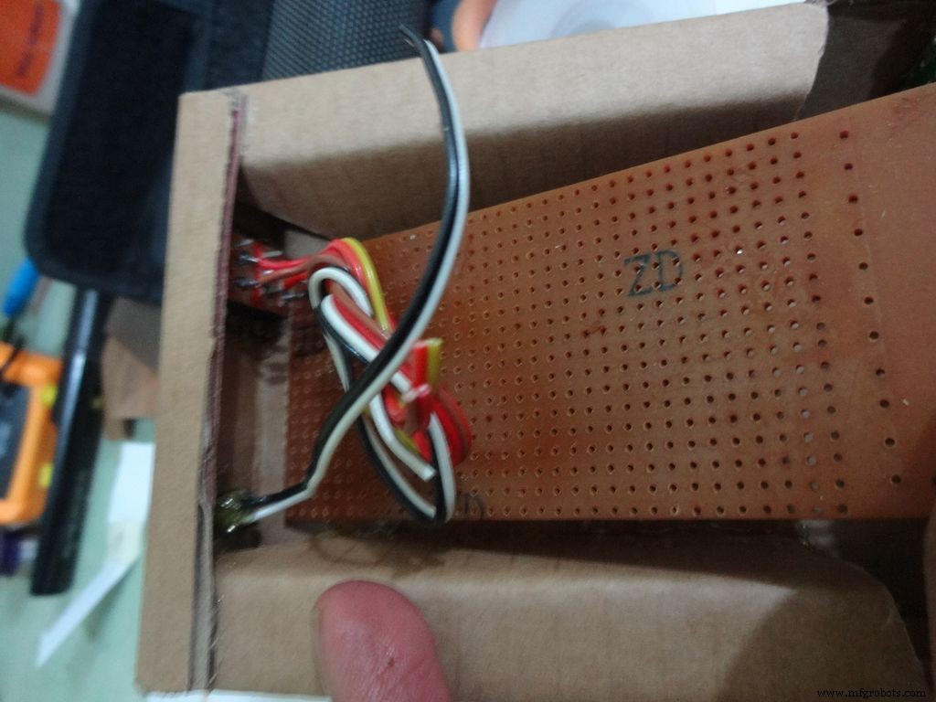
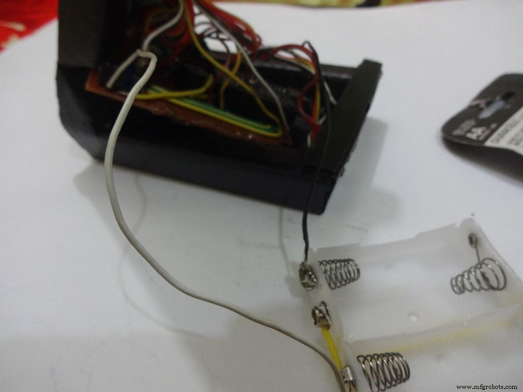
Solder Wires to the case, strip and tin them. Solder the positive end to the middle pin of power switch and negative end to ground.
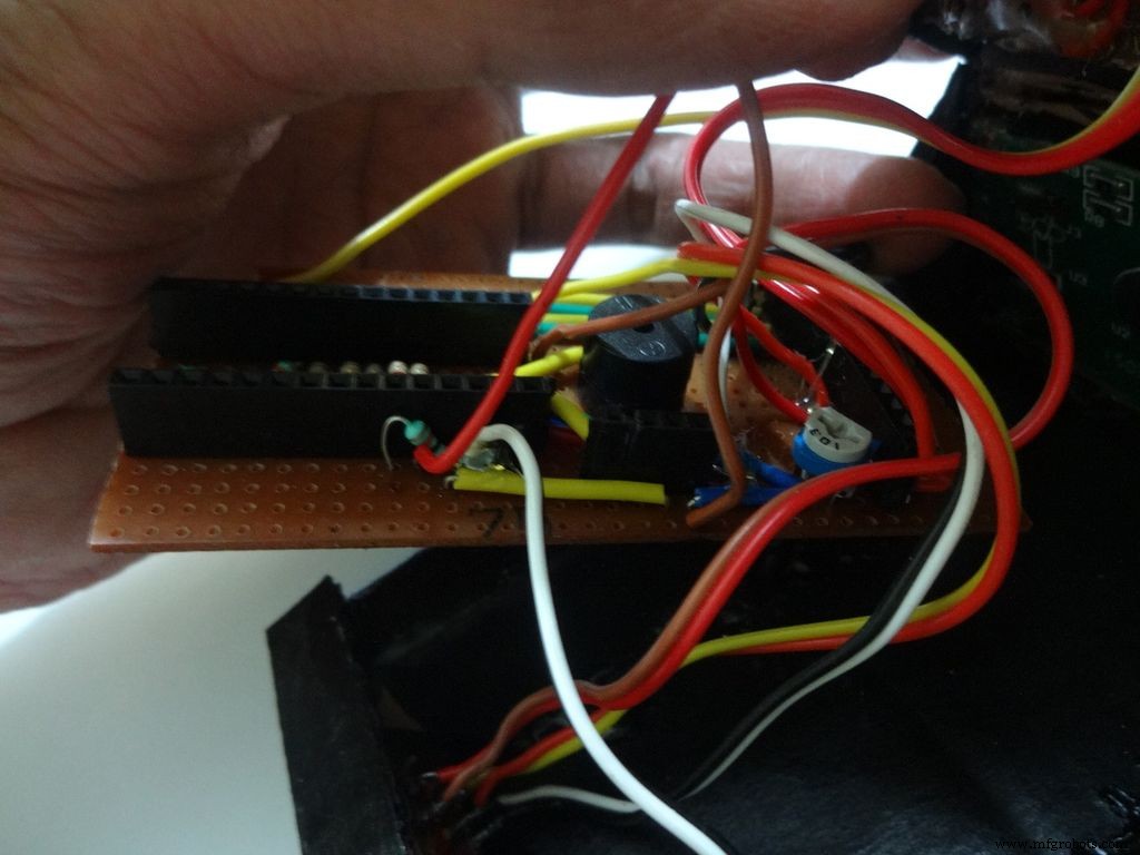
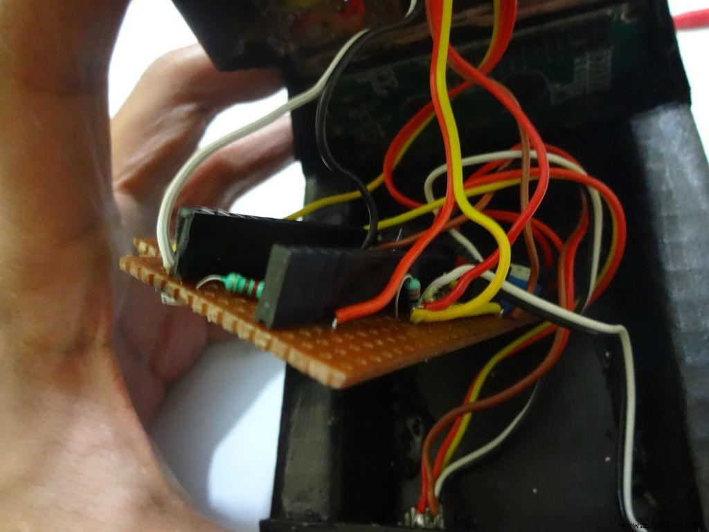
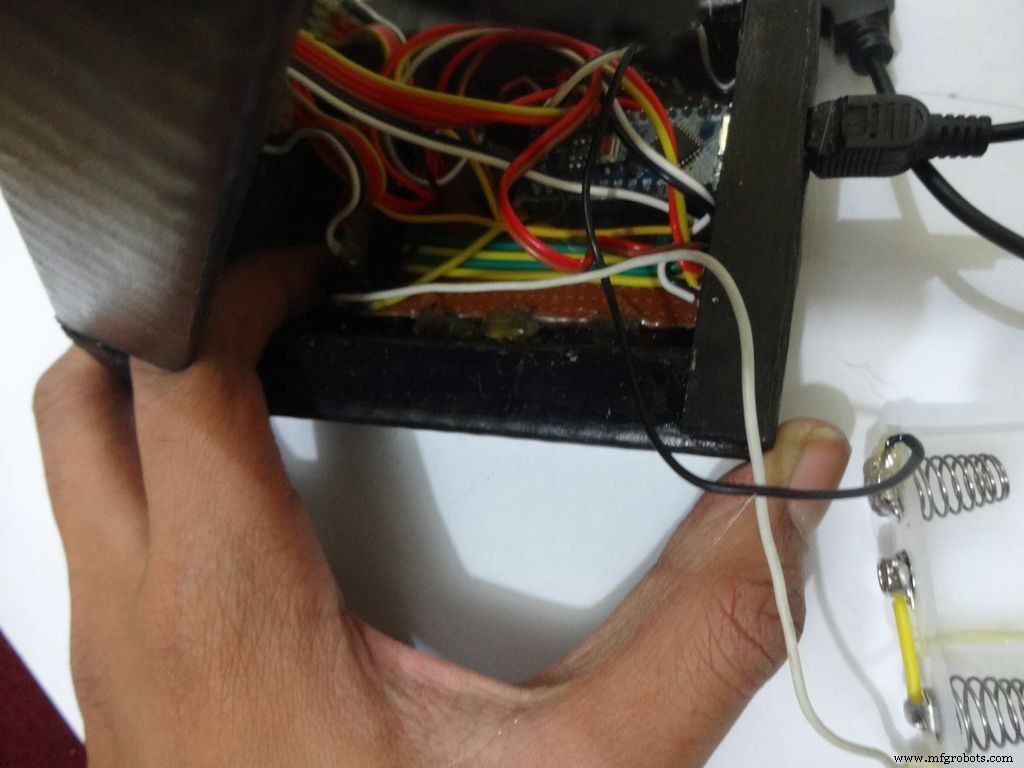
Glue the PCB to the base after making all the connections.
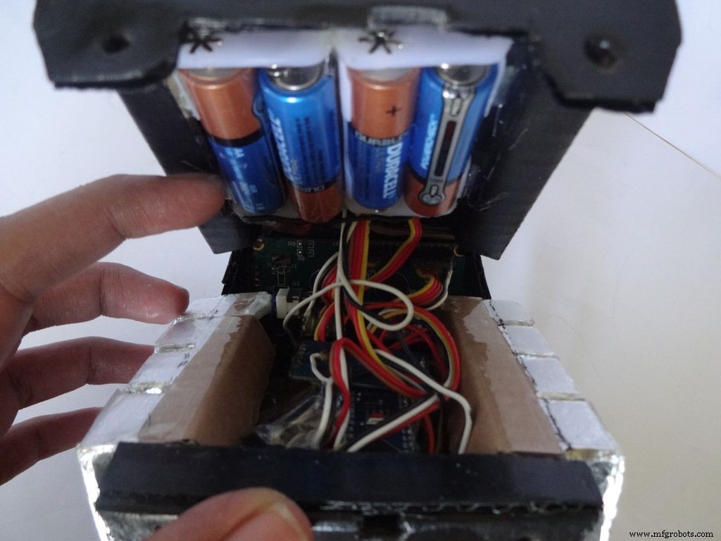
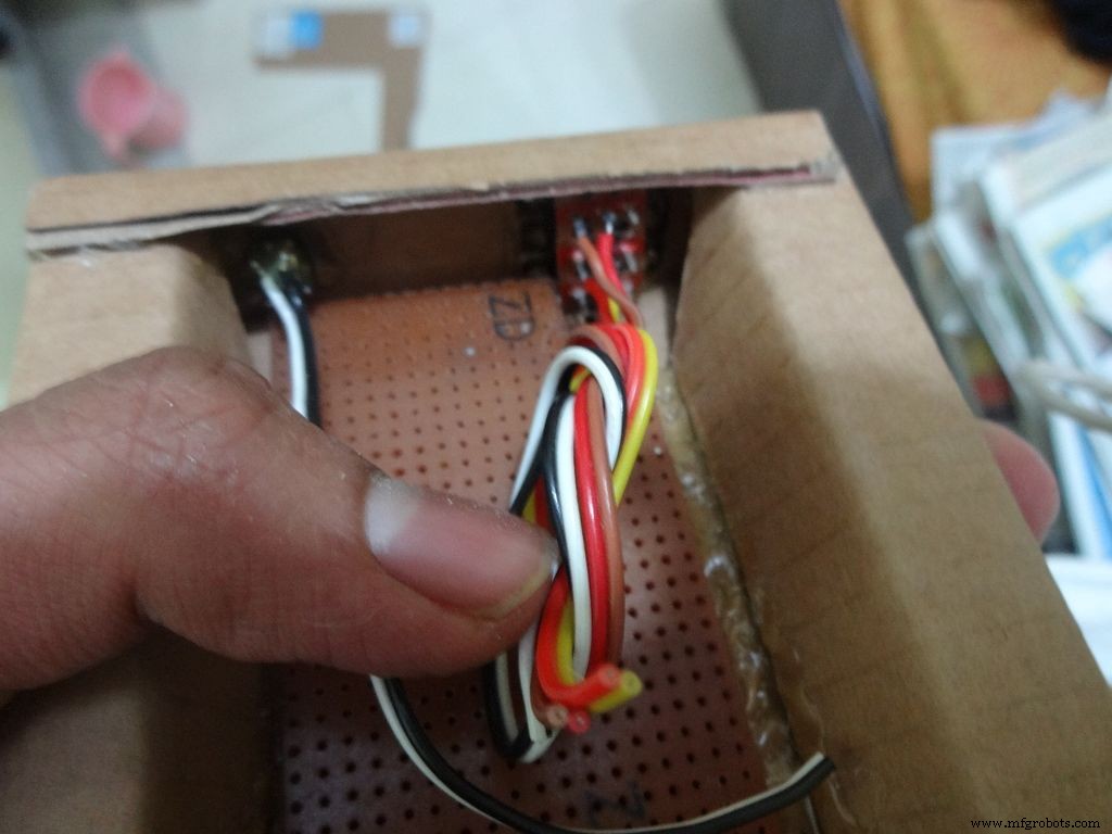
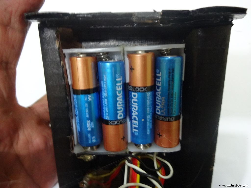
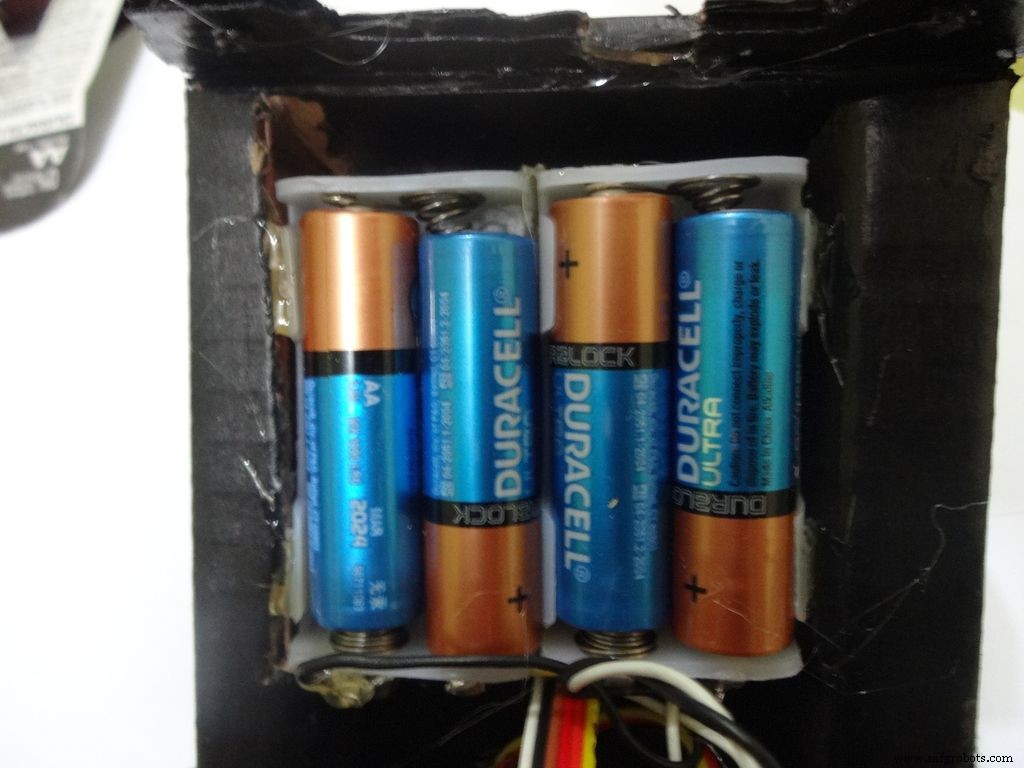
Twist the wires and place them in position. Insert batteries(the case expands a bit on inserting batteries) and glue the case to the cover.
Step 32:Adding the Legs
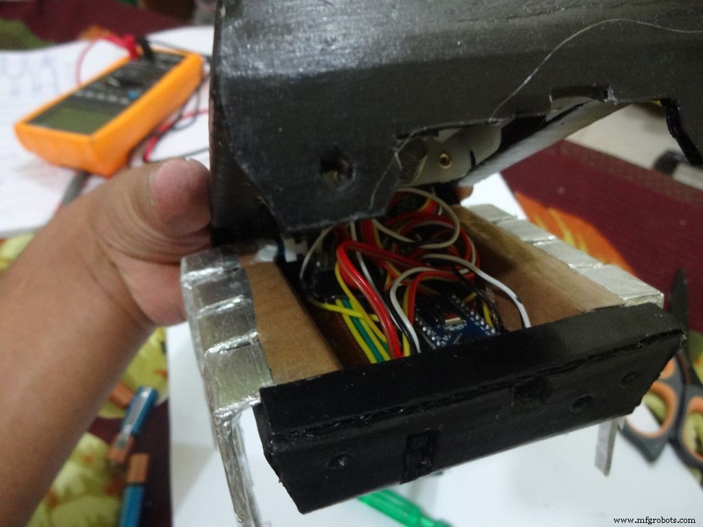
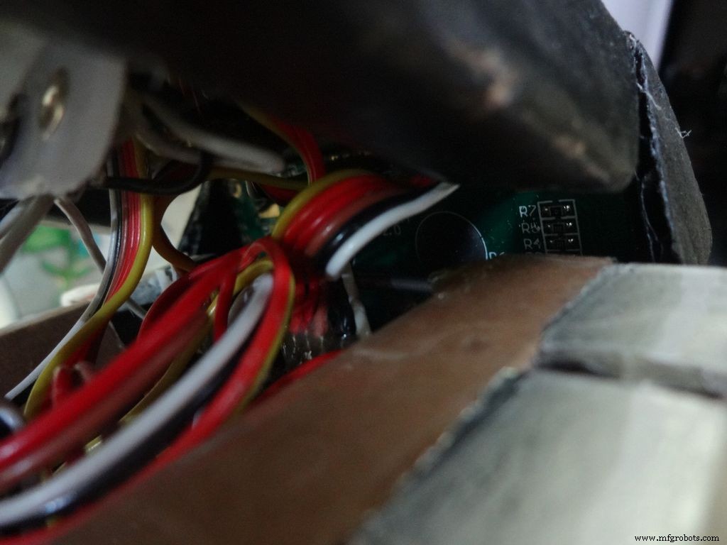
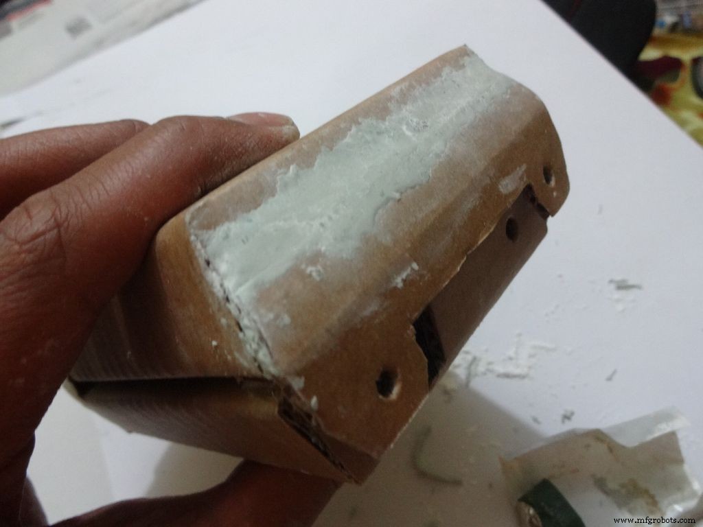
Cut the inner part of legs so that it fits in properly. Stick it it place.
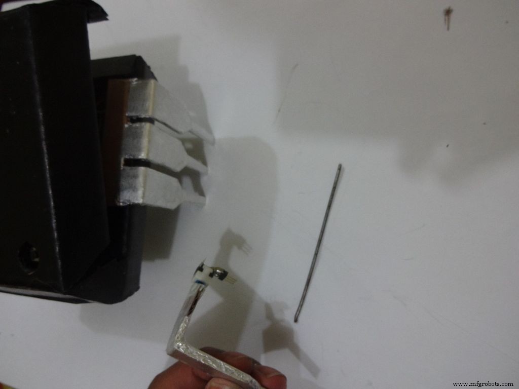
Put the power switch pin in to check if it fits in perfectly. Remove it, add a metal rod, piece of wood or anything strong of proper length that will prevent the switch from moving back. Glue it in place.
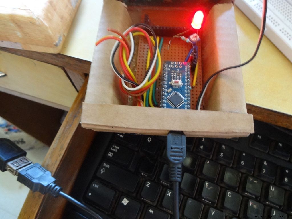
Check the switch, it should be turning on/off smoothly.
Switch on the IC and test all the functions. If its not working skip to the troubleshooting section.
Step 33:Finishing up!
Use M-seal (or equivalent) to fill any small gaps around the testing area and the mode change button. After drying, sand it well and apply a second layer of paint.
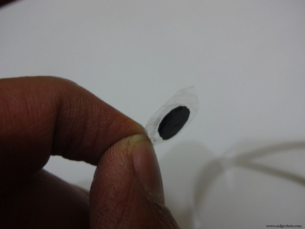
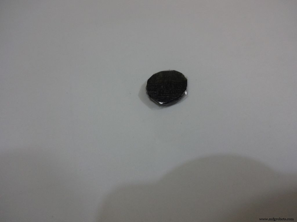
Make the button with a small piece of cardboard, paint it black and cover it with tape(gives a shiny finish). Apply a tiny drop of glue and stick the button in place.
Step 34:Problems and Troubleshooting

Do everything correctly. This is the most boring most of any project and you dont wanna get here just because you soldered the wrong pins!
- Recheck every soldered joint and ensure that it isnt touching the adjacent one. Use the multimeter continuity test for help.
- After cutting component/jumper leads make sure the cut lead doesnt fall underneath the PCB. This may lead to unwanted shorting soldered joints.
- Write down anything you need to remember in a book, don't trust your memory.
- If LCD is not displaying, make sure the contrast is adjusted properly. Also make sure the pin0 and 1 switches are turned ON. Check all the pin connections from LCD to Arduino with continuity test. Use breadboard jumpers wherever your mutimeter cant reach.
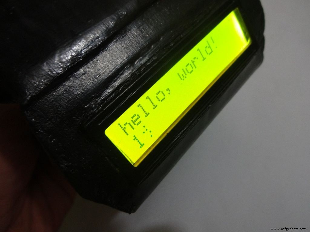
- Upload the hello world LCD program to see if the problem is in the code.
- If a particular function is not working, check its connections and tally it with the code.
- And most importantly, keep your curious pets with their evil minds away from your workspace! :p
Step 35:Things I did, some mistakes I made
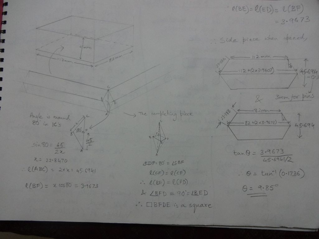

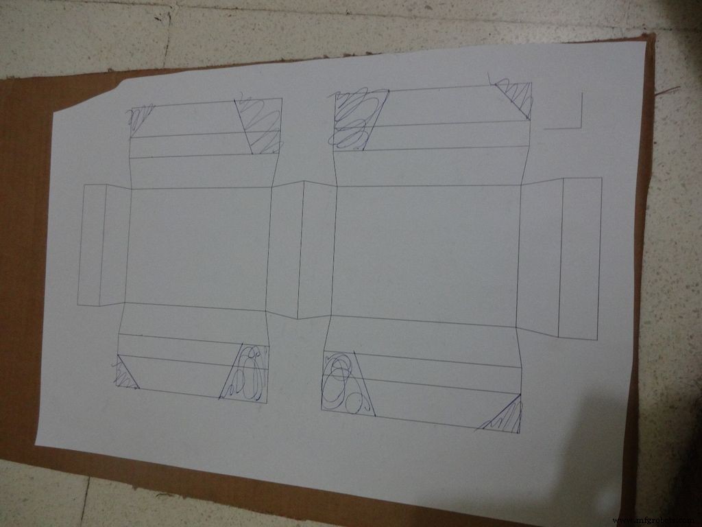
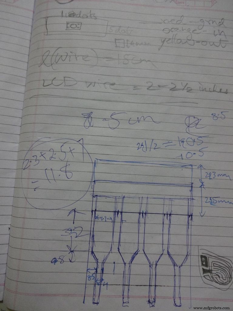
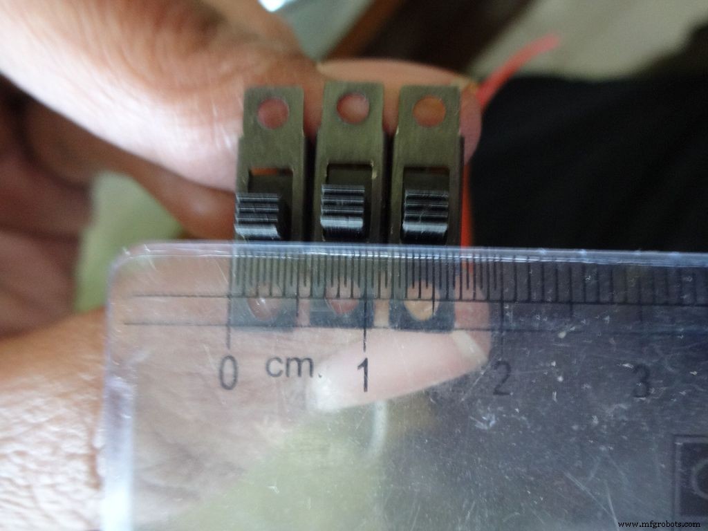
While testing the various circuits and when I had the rough idea of what I want to make, I decided to go with the IC design. I measured actual ICs, took ratios of their lengths, got the angle with some trignometry to be around 80 degrees. Then I decided the inner box length and breadth and built upon it(shown in image). Once the layout was planned, I initially started to draw it accurately on a large size paper. After a bit of a struggle of drawing accurate lines, I realised that this kind of work should be done on a computer! So I learnt CAD basics and succesfully made the layout on it. :) But this layout didnt work out and I had to redo the entire cutting and making of the case.(See images)
While removing the LEDs on the Arduino Nano I used excess pressure to remove a stubborn LED, and ended up removing a PCB pad. Always desolder without forcing/applying pressure on the joints, the pads are delicate and easily come off if you dont stay calm.
When all the solder joints were made and project was about to get finished, in excitement and eagerness, I glued the PCB inside the case before adding the battery case. Had to re-melt the hot glue with a soldering iron (carefully not to melt any wire insulation) and remove the PCB out to solder the battery case wires in. The soldering iron can be cleaned afterwards.
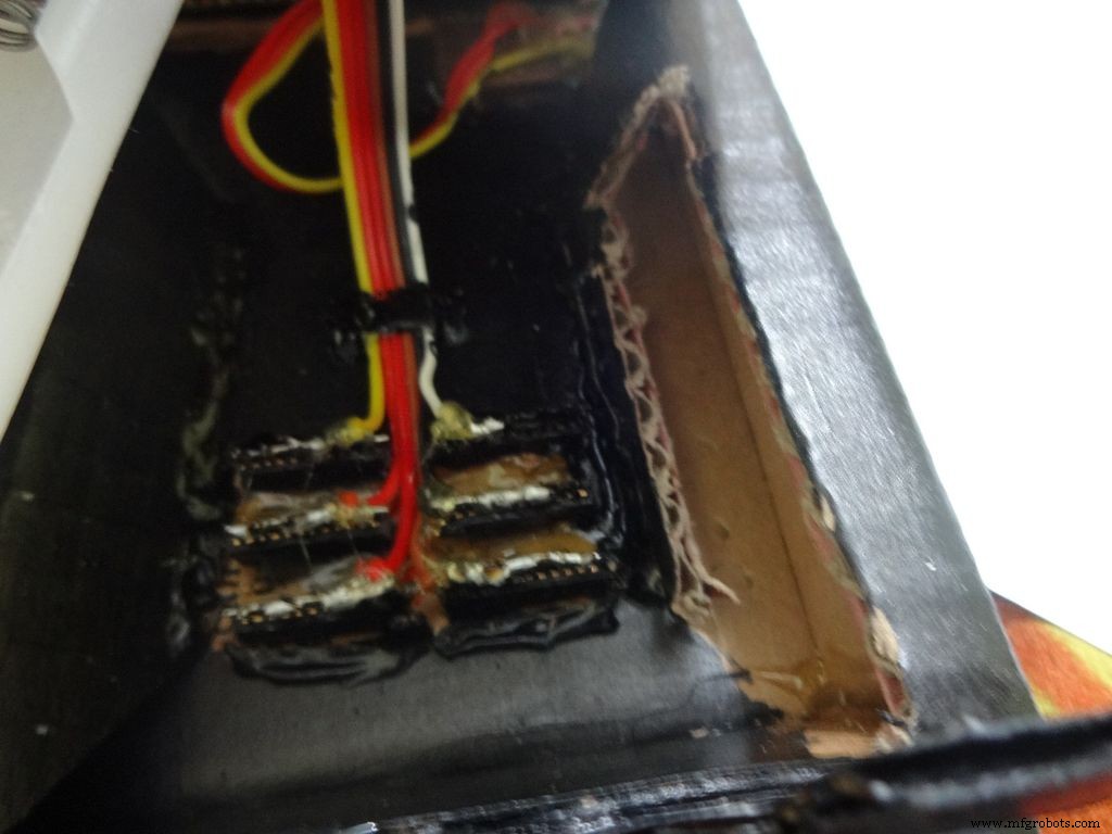
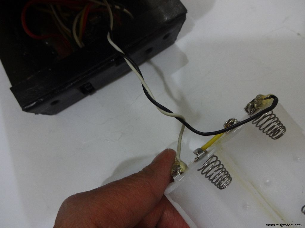
The RTC module battery was coming in way of the batteries while closing and so I separated the battery holder(Warning:desolder only with the battery removed) and added extension wires so that the battery can be placed at the sides where there is space.
All the Layout PDFs, CAD Files and the Main code can be downloaded here:Google Drive
Code
- Codefragment #1
- Codefragment #2
- Codefragment #3
- Codefragment #4
Codefragment #1Platte tekst
//Analog pin used to find resistanceint Apin=7;//values of r1 to r5float r1=1000;float r2=4700;float r3=10000;float r4=47000;float r5=100000;//pins of r1 to r5int r1_pin=2;int r2_pin=3;int r3_pin=4;int r4_pin=5;int r5_pin=6;float reading=0; //read from analog pin and store herefloat R=0; //calculate unknown and store hereString finalR; //final value to be displayed along with unitsint caseno; //for debugging, stores the case number // we divide the entire range into cases and assign each a number, // total 5 cases // case1 :less than 2850 // case2 :2850 to 7350 // case3 :7350 to 28500 // case4 :28500 to 73500 // case5 :more than 73500#include// needed for converting float to string, //has the String(float,n) function. Explained below.void setup() { Serial.begin(9600);}void loop() { //first we find unknown resistance using 1kOhm resistor //Therefore, disable R2, R3, R4 and R5 digitalWrite(r2_pin, LOW); //turn each pin to LOW before setting it as INPUT pinMode(r2_pin, INPUT); // turning it to INPUT when its HIGH enables the // internal pullup resistor digitalWrite(r3_pin, LOW); pinMode(r3_pin, INPUT); digitalWrite(r4_pin, LOW); pinMode(r4_pin, INPUT); digitalWrite(r5_pin, LOW); pinMode(r5_pin, INPUT); pinMode(r1_pin, OUTPUT); digitalWrite(r1_pin, HIGH); //read and calculate resistance reading=analogRead(Apin); R=(reading*r1)/(1023-reading); // if value <2850, finalR =value(using 1kOhm) if(R<2850){ caseno=1; if(R<1000){ //if value less than 1000 use "Ohm" not "kOhm" finalR =String(R,2) + "Ohm"; //String(float,n) Converting float to string //with n digits after decimal // attach "Ohm" after value to the string, //'+' joins two strings here } else{ //use "kOhm R=R/1000; finalR =String(R,2) + "kOhm"; } } //if value between 2850 and 7350 , use value obtained by 4.7kOhm else if(R>=2850 &&R<7350){ caseno=2; digitalWrite(r1_pin, LOW); //Enable only 4.7kOhm pinMode(r1_pin, INPUT); digitalWrite(r3_pin, LOW); pinMode(r3_pin, INPUT); digitalWrite(r4_pin, LOW); pinMode(r4_pin, INPUT); digitalWrite(r5_pin, LOW); pinMode(r5_pin, INPUT); pinMode(r2_pin, OUTPUT); digitalWrite(r2_pin, HIGH); reading=analogRead(Apin); R=(reading*r2)/(1023-reading)/1000; finalR =String(R,2) + "kOhm"; } //if value between 7350 and 28500, use value obtained by 10kOhm else if(R>=7350 &&R<28500){ caseno=3; digitalWrite(r1_pin, LOW); pinMode(r1_pin, INPUT); digitalWrite(r2_pin, LOW); pinMode(r2_pin, INPUT); digitalWrite(r4_pin, LOW); pinMode(r4_pin, INPUT); digitalWrite(r5_pin, LOW); pinMode(r5 _pin, INPUT); pinMode(r3_pin, OUTPUT); digitalWrite(r3_pin, HIGH); reading=analogRead(Apin); R=(reading*r3)/(1023-reading)/1000; finalR=String(R,2) + "kOhm"; } //if value between 28500 and 73500, use value obtained by 47kOhm else if(R>=28500 &&R<73500){ caseno=4; digitalWrite(r1_pin, LOW); pinMode(r1_pin, INPUT); digitalWrite(r2_pin, LOW); pinMode(r2_pin, INPUT); digitalWrite(r3_pin, LOW); pinMode(r3_pin, INPUT); digitalWrite(r5_pin, LOW); pinMode(r5_pin, INPUT); pinMode(r4_pin, OUTPUT); digitalWrite(r4_pin, HIGH); reading=analogRead(Apin); R=(reading*r4)/(1023-reading)/1000; finalR =String(R,2) + "kOhm"; } //if value more than 73500, use value obtained by 100kOhm else if(R>=73500){ caseno=5; digitalWrite(r1_pin, LOW); pinMode(r1_pin, INPUT); digitalWrite(r2_pin, LOW); pinMode(r2_pin, INPUT); digitalWrite(r3_pin, LOW); pinMode(r3_pin, INPUT); digitalWrite(r4_pin, LOW); pinMode(r4_pin, INPUT); pinMode(r5_pin, OUTPUT); digitalWrite(r5_pin, HIGH); reading=analogRead(Apin); R=(reading*r5)/(1023-reading)/1000; finalR =String(R,2) + "kOhm"; } Serial.println(finalR); //printing the final string with units Serial.println(" "); vertraging (1000); }
Codefragment #2Platte tekst
/* RCTiming_capacitance_meter * code concept taken from Paul Badger 2008 * * The capacitor's voltage at one time constant is defined as * 63.2% of the charging voltage. * i.e, A Capacitor is filled to 63.2% of its total capacity in * 1 Time Constant */ int analogPin=0; // analog pin for measuring capacitor voltage int chargePin=7; // pin to charge the capacitor - connected to // one end of the charging resistor int dischargePin=12; // pin to discharge the capacitor, // same used for diode test(checkPin1) float resistorValue=10000.0; // We use 10kOhm resistor unsigned long startTime; unsigned long elapsedTime; float microFarads; // floating point variable to preserve precision float nanoFarads;void setup(){ pinMode(chargePin, OUTPUT); // set chargePin to output digitalWrite(chargePin, LOW); Serieel.begin(9600); // initialize serial transmission for debugging}void loop(){ digitalWrite(chargePin, HIGH); // set chargePin HIGH and capacitor charging startTime =millis(); while(analogRead(analogPin) <648){ // just wait and do nothing till 648 // 647 is 63.2% of 1023, // which corresponds to full-scale voltage } elapsedTime=millis() - startTime; // convert milliseconds to seconds ( 10^-3 ) // and Farads to microFarads ( 10^6 ), net 10^3 (1000) microFarads =((float)elapsedTime / resistorValue) * 1000; // (float) converts "unsigned long" elapsed time to float Serial.print(elapsedTime); // print the value to serial port Serial.print(" mS "); // print units if (microFarads> 1){ Serial.print((long)microFarads); // print the value to serial port Serial.println(" microFarads"); // print units } else { // if value is smaller than one microFarad, convert to nanoFarads (10^-9 Farad). nanoFarads =microFarads * 1000.0; // multiply by 1000 to convert to nanoFarads (10^-9 Farads) Serial.print((long)nanoFarads); // print the value to serial port Serial.println(" nanoFarads"); // print units } /* dicharge the capacitor */ digitalWrite(chargePin, LOW); // set charge pin to LOW pinMode(dischargePin, OUTPUT); // set discharge pin to output digitalWrite(dischargePin, LOW); // set discharge pin LOW while(analogRead(analogPin)> 0){ // wait until capacitor is completely discharged } pinMode(dischargePin, INPUT); // set discharge pin back to input} Codefragment #3Platte tekst
String state ="null"; //prints "null" for reverse bias or nothing connectedint checkPin1 =12;int checkPin2 =6;void setup() { Serial.begin(9600);}void loop() {pinMode(checkPin1, OUTPUT); digitalWrite(checkPin1, LOW); //pin 11 is set to low//analog read is normally pulled up by the 10k resistor, so null reading is 1023//In forward bias, the analog pin gets connected to checkPin1, which is LOW. So reading less than 1023//Practically a small current flows in reverse bias as well, so we take 700 to differentiate if(analogRead(checkPin2)<700){ state="forward"; } Serial.println(state); Serial.println(analogRead(checkPin2)); state ="null"; vertraging(500);} Codefragment #4Platte tekst
// Date and time functions using a DS1307 RTC connected via I2C and Wire lib#include #include RTC_DS1307 rtc;//creating "rtc" object of RTC_DS1307, objects are used to access functions //more on objects and classes:https://www.youtube.com/watch?v=ABRP_5RYhqUchar daysOfTheWeek[7][12] ={"Sunday", "Monday", "Tuesday", "Wednesday", "Thursday", "Friday", "Saturday"};void setup () { Serial.begin(9600); rtc.begin(); // following line sets the RTC to the date &time this sketch was compiled // rtc.adjust(DateTime(F(__DATE__), F(__TIME__))); // This line sets the RTC with an explicit date &time, for example to set // January 21, 2014 at 3am you would call:// rtc.adjust(DateTime(2014, 1, 21, 3, 0, 0));}void loop () { DateTime now =rtc.now(); Serial.print(now.year()); Serial.print('/'); Serial.print(now.month()); Serial.print('/'); Serial.print(now.day()); Serial.print(" ("); Serial.print(daysOfTheWeek[now.dayOfTheWeek()]); Serial.print(") "); Serial.print(now.hour()); Serial.print(':'); Serial.print(now.minute()); Serial.print(':'); Serial.print(now.second()); Serieel.println(); Serieel.println(); vertraging(1000);} Github
https://github.com/adafruit/RTClibhttps://github.com/adafruit/RTClibSchema's
Main_Schematic.fzzProductieproces