


Spectrino:TinyML Arduino &IoT-gebaseerde aanraakvrije oplossingen
Componenten en benodigdheden
 |
| × | 1 | |||
 |
| × | 1 | |||
| × | 1 | ||||
| × | 1 | ||||
 |
| × | 1 | |||
 |
| × | 2 | |||
| × | 1 | ||||
| × | 1 | ||||
 |
| × | 1 | |||
 |
| × | 1 | |||
 |
| × | 1 |
Benodigde gereedschappen en machines
 |
|
Apps en online services
 |
| |||
 |
| |||
 |
| |||
 |
|
Over dit project
Overzicht
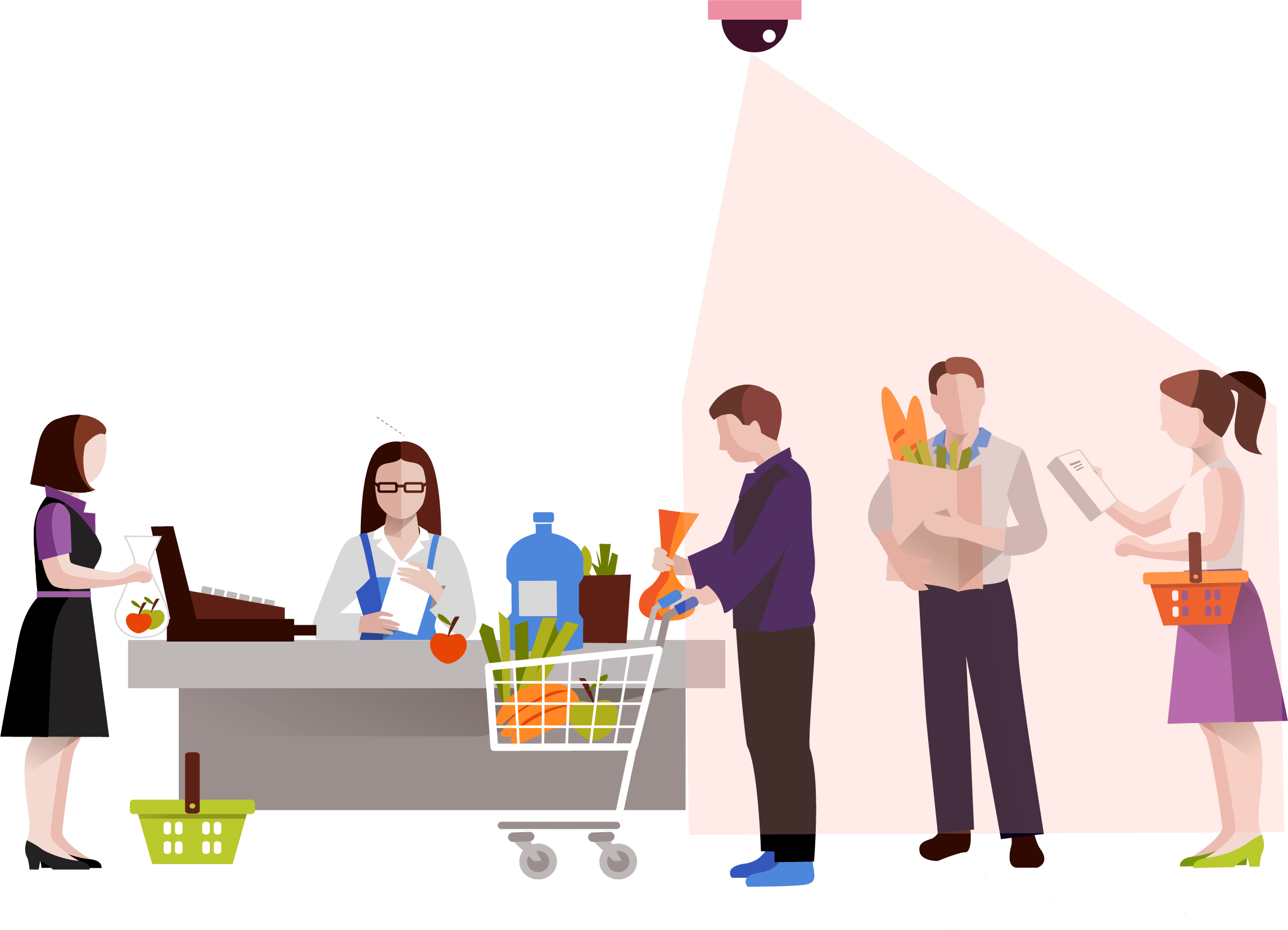
De pandemie heeft een beperking ingevoerd voor sociale interactie:afstand. Gezien deze risicofactor hebben landen over de hele wereld verschillende niveaus van quarantaine doorgemaakt en hebben veel winkelcentra hun deuren moeten sluiten vanwege aanzienlijk verlaagd aantal consumenten . Dit heeft geleid tot een zeer, zeer hoog aantal ontslagen van winkelpersoneel , evenals vergelijkbare economische uitdagingen voor bedrijfseigenaren .
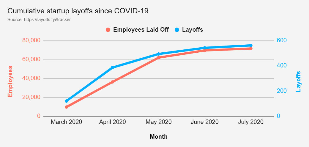
Dit heeft geleid tot een relatief laag inkomen (minder dan $ 40.000 aan jaarlijkse inkomsten) banenverlies vanaf 2 juli 2020 in de VS als gevolg van COVID-19. Accommodatie en voedseldiensten, evenals detailhandel en entertainment tellen samen voor ongeveer 4.000.000 verloren banen.
De economische uitdaging waarmee verschillende industrieën worden geconfronteerd, waarbij Food, Consumer en Retail in de Top 6 van industrieën met het hoogste aantal ontslagen werknemers komen (naar schatting meer dan 20.000 banen). Ervan uitgaande dat "Internationaal" alle niet-Amerikaanse gebieden omvat waarmee dit onderzoek rekening houdt, bereikt het totale aantal ontslagen wereldwijd naar schatting 103.000+ banen.
COMPLICATIE
Gezien de gegeven gegevens heeft het team vastgesteld dat het een grote uitdaging is dat er onzekerheid bestaat over het risico, met betrekking tot de bevolkingsdichtheid in verschillende winkels, voor de winkelcentra die nog open zijn. Afgezien hiervan, terwijl het dragen van gezichtsmaskers en het vermijden van aanraking op veel plaatsen verplicht is, zijn er nog steeds overtredingen. Dit maakt het moeilijker voor winkelpersoneel en ondernemers, die het zich niet kunnen veroorloven om op afstand te werken, om veilig door deze nieuwe normale werkruimte te navigeren. Dit roept de vraag op:hoe kunnen we met een behoorlijke zekerheid garanderen dat een bepaalde winkel in het winkelcentrum op elk moment veilig kan worden betreden?
We strijden nu allemaal tegen de heersende COVID-19 pandemie. En ook, nu bevinden we ons in een situatie waarin we ons met meer veiligheidsmaatregelen moeten aanpassen aan de heersende omstandigheden. Terwijl het leven weer normaal wordt met meer veiligheidsmaatregelen om virusinfectie te voorkomen, heerst er ook in de steden meer veiligheid op de openbare plaatsen en drukke gebieden. Maar er waren veel situaties waarin we de veiligheidsmaatregelen moesten overtreden en interactie moesten hebben met een onveilig element om de behoeftigen te ontmoeten. Hier houdt het project zich bezig met het voorkomen van verspreiding van COVID-19 via aanrakingen of aanrakingen.
Er was een experiment uitgevoerd om de verspreiding van een virus door aanraking te zien. De resultaten werden als volgt geëvalueerd:
Daarom heb ik besloten om de meest gebruikte apparaten in woningen en samenlevingen te automatiseren om handsfree communicatie met apparaten te garanderen.
Bij het maken van dit prototype zijn de volgende oplossingen ontwikkeld
- Slim intercomsysteem met TinyML geïmplementeerd op Arduino33 BLE Sense: Het volgende is een aanraakvrije oplossing met behulp van Computer Vision en een TinyML-model om een persoon buiten de deur te detecteren en een bel te laten rinkelen zonder dat de persoon de bel aanraakt.
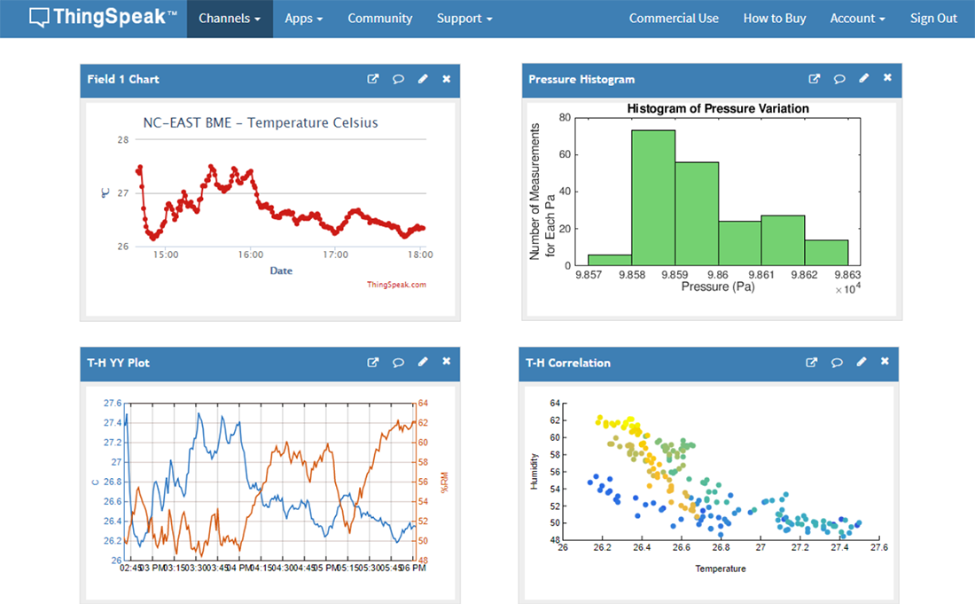
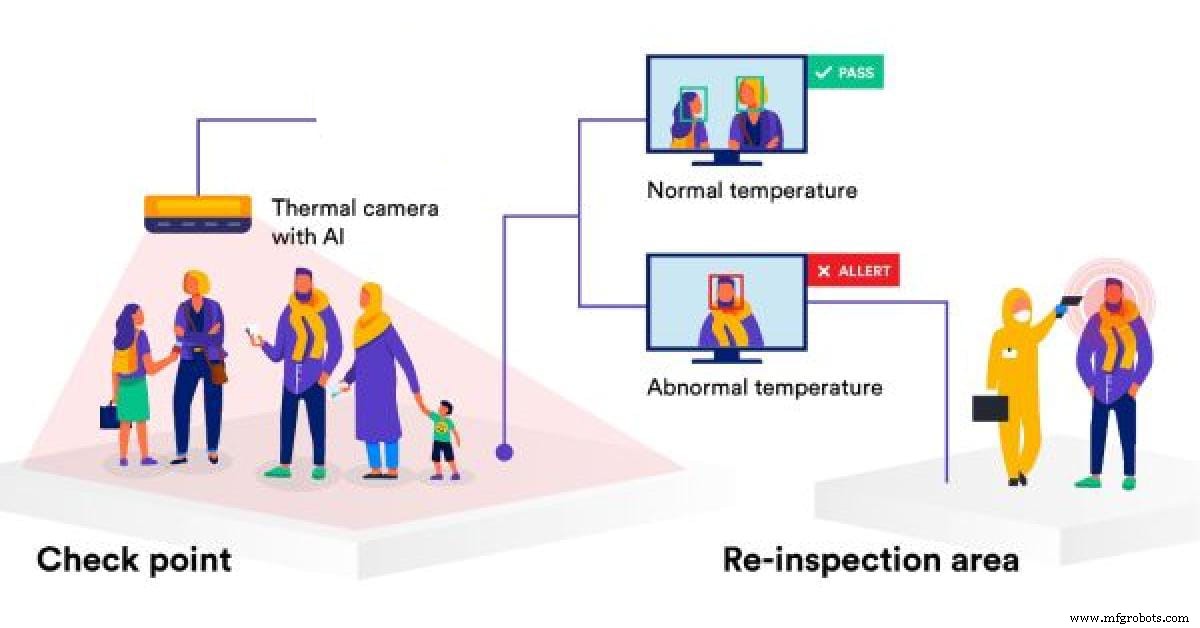
- Temperatuurbewakingssysteem Met behulp van IoT en waarschuwingssysteem: Te midden van de pandemie is veiligheid een belangrijk aspect geworden. Daarom maakt het Temperature Monitoring-systeem gebruik van het IoT Thingspeak-dashboard en detecteert het mensen bij het binnenkomen en meet het hun temperatuur. Deze temperatuur wordt weergegeven op een IoT Dashboard voor tijdige trends en data-analyse. Bij abnormale temperatuurdetectie worden waarschuwingen gegenereerd waarop de persoon een tweede inspectie ondergaat.
- Touch-Free liftsysteem met spraakherkenning TinyML-model op Arduino BLE 33 sense: We gebruiken liften om meerdere keren per dag in een gebouw omhoog of omlaag te gaan en ik ben altijd bang om vervuilde schakelaars aan te raken die zijn aangeraakt door andere mensen die pendelen. Vandaar dat dit spraakherkenningsmodel zal identificeren wanneer een persoon naar boven of naar beneden wil gaan en op dezelfde manier de actie zal uitvoeren.
- MaskModel-detectiesysteem op basis van TinyML en IoT-bewakingssysteem: Deze methode maakt gebruik van een computervisiemodel dat is geïmplementeerd op Arduino BLE 33 sense om te detecteren of een persoon een masker heeft gedragen of niet en op dezelfde manier worden deze gegevens naar een IoT-dashboard gestuurd voor monitoring en het opleggen van beperkingen op basis van onveilige tijden.
- Smart Queue monitoring en opzetten systeem in een supermarkt of een winkelcentrum met TinyML, IoT en computer vision: Dit model detecteert een persoon die buiten de supermarkt staat en laat 50 mensen tegelijk binnen in de supermarkt. Het zal nog een kwartier wachten om de mensen binnen hun boodschappen te laten doen en de volgende 50 mensen weer het winkelcentrum in te laten. Dit zal worden gedaan met behulp van computervisie en TinyML geïmplementeerd op een Arduino 33 BLE-sense. Deze gegevens worden vervolgens geprojecteerd op een IoT-dashboard waar realtime gegevens kunnen worden gevolgd.
- Persoonsbewakingssysteem in een gangpad in een winkelcentrum en op besmetting gebaseerd desinfectiesysteem :Deze oplossing maakt gebruik van een persoonsdetectie-algoritme dat wordt gebruikt in een gebied in een winkelcentrum of een supermarkt en als de persoonsbesmetting in een gebied de drempel heeft overschreden, reinigt het het gebied zelf met UV-licht. De Sanitization periode en tijden worden geprojecteerd op een IoT Dashboard voor het supermarktpersoneel voor analyse.
Opzetten (Vereisten voor het project):
Hardware vereist:
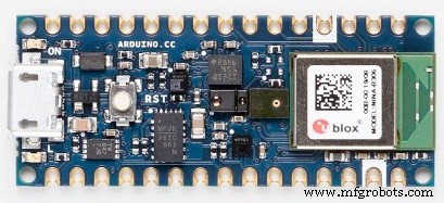
1)Arduino33BLE zin
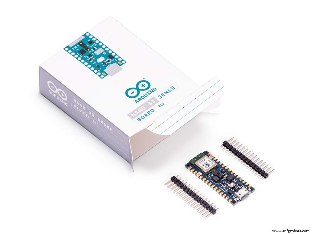
De Arduino Nano 33 BLE Sense is een evolutie van de traditionele Arduino Nano, maar met een veel krachtigere processor, de nRF52840 van Nordic Semiconductors, een 32-bits ARM® Cortex™-M4 CPU die draait op 64 MHz. Hiermee kun je grotere programma's maken dan met de Arduino Uno (hij heeft 1 MB programmageheugen, 32 keer groter), en met veel meer variabelen (het RAM-geheugen is 128 keer groter). De hoofdprocessor bevat andere geweldige functies, zoals Bluetooth®-koppeling via NFC en modi met ultralaag stroomverbruik.
Ingebouwde kunstmatige intelligentie
Het belangrijkste kenmerk van dit bord, naast de indrukwekkende selectie sensoren, is de mogelijkheid om Edge Computing-applicaties (AI) erop te draaien met behulp van TinyML. U kunt uw machine learning-modellen maken met TensorFlow™ Lite en ze uploaden naar uw bord met behulp van de Arduino IDE.
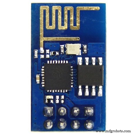
2)ESP8266 ESP-01
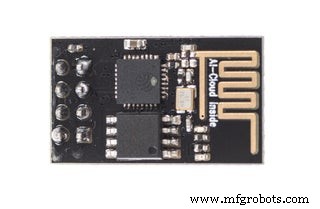
De ESP8266 ESP-01 is een Wi-Fi-module waarmee microcontrollers toegang tot een Wi-Fi-netwerk . Deze module is een op zichzelf staande SOC (System On a Chip) die niet per se een microcontroller nodig heeft om inputs en outputs te manipuleren zoals je normaal zou doen met een Arduino , bijvoorbeeld omdat de ESP-01 fungeert als een kleine computer. Afhankelijk van de versie van de ESP8266 is het mogelijk om tot 9 GPIO's (General Purpose Input Output) te hebben. Zo kunnen we een microcontroller internettoegang geven zoals het Wi-Fi-schild dat doet voor de Arduino, of we kunnen de ESP8266 eenvoudig programmeren om niet alleen toegang te hebben tot een Wi-Fi-netwerk, maar ook om als microcontroller te fungeren. Dit maakt de ESP8266 zeer veelzijdig.
3)Arducam Mini 2MP plus
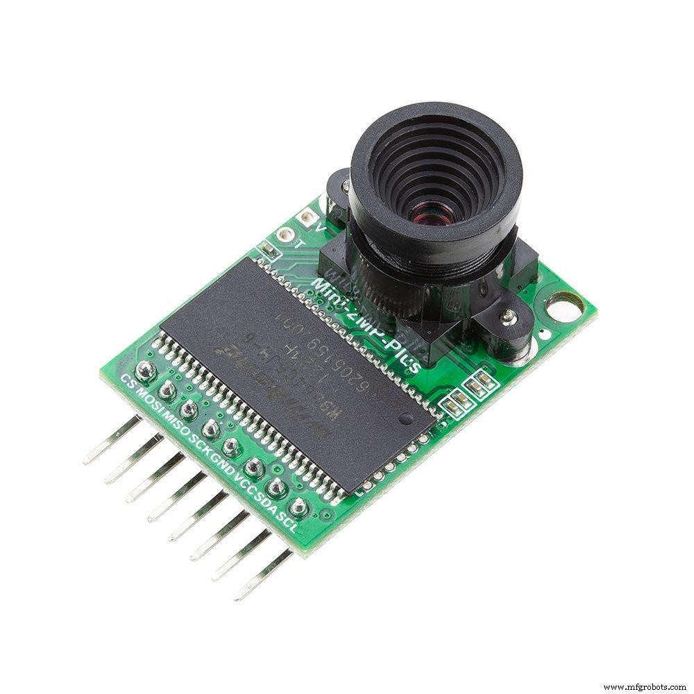
ArduCAM-2MP-Plus is een geoptimaliseerde versie van ArduCAM shield Rev.C, en is een high-definition 2MP SPI-camera, die de complexiteit van de camerabesturingsinterface vermindert. Het integreert 2 MP CMOS-beeldsensor OV2640 en biedt miniatuurformaat, evenals de gebruiksvriendelijke hardware-interface en open source codebibliotheek.
De ArduCAM mini kan worden gebruikt in alle platforms zoals Arduino, Raspberry Pi, Maple, Chipkit, Beaglebone Black, zolang ze een SPI- en I2C-interface hebben en goed kunnen worden gecombineerd met standaard Arduino-boards. ArduCAM mini biedt niet alleen de mogelijkheid om een camera-interface toe te voegen die bij sommige goedkope microcontrollers niet aanwezig is, maar biedt ook de mogelijkheid om meerdere camera's aan een enkele microcontroller toe te voegen.
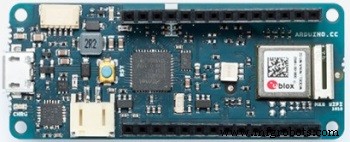
4) Arduino MKR WiFi 1010:
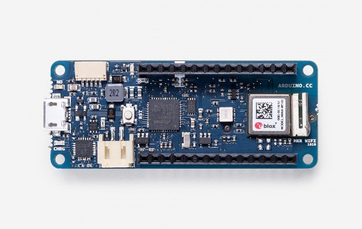
De Arduino MKR WiFi 1010 is het gemakkelijkste toegangspunt tot het basisontwerp van IoT- en pico-netwerktoepassingen. Of u nu een sensornetwerk wilt bouwen dat is aangesloten op uw kantoor- of thuisrouter, of als u een BLE-apparaat wilt maken dat gegevens naar een mobiele telefoon verzendt, de MKR WiFi 1010 is uw totaaloplossing voor veel van de elementaire IoT-toepassingen scenario's.
De hoofdprocessor van het bord is een Arm® Cortex®-M0 32-bit SAMD21 met laag vermogen, zoals in de andere borden binnen de Arduino MKR-familie. De WiFi- en Bluetooth®-connectiviteit wordt uitgevoerd met een module van u-blox, de NINA-W10, een chipset met laag vermogen die werkt in het 2,4 GHz-bereik. Bovendien is veilige communicatie verzekerd via de Microchip® ECC508-cryptochip. Daarnaast vind je een batterijlader en een richtbare RGB LED aan boord.
Softwaretools:
1)Arduino-webeditor
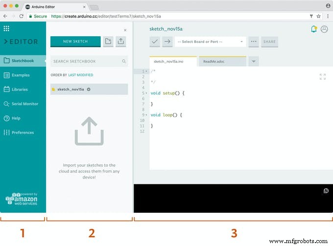
Arduino Create is een geïntegreerd online platform waarmee makers en professionele ontwikkelaars code kunnen schrijven, inhoud kunnen openen, borden kunnen configureren en projecten kunnen delen. Ga sneller dan ooit van een idee naar een voltooid IoT-project. Met Arduino Create kun je een online IDE gebruiken, meerdere apparaten verbinden met de Arduino IoT Cloud, door een verzameling projecten bladeren op Arduino Project Hub en op afstand verbinding maken met je boards met Arduino Device Manager. Je kunt ook je creaties delen, samen met stapsgewijze handleidingen, schema's, referenties en feedback van anderen ontvangen.
2)Edge Impulse Studio:
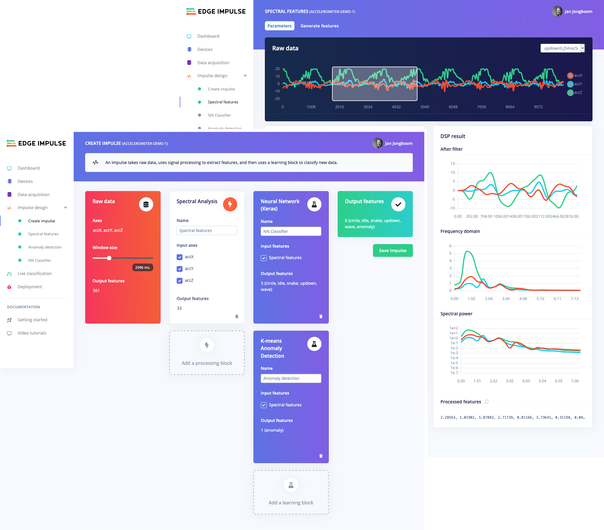
De trend om ML op microcontrollers uit te voeren, wordt soms Embedded ML of Tiny ML genoemd. TinyML heeft het potentieel om kleine apparaten te maken die slimme beslissingen kunnen nemen zonder gegevens naar de cloud te hoeven sturen - geweldig vanuit een efficiëntie- en privacyperspectief. Zelfs krachtige deep learning-modellen (gebaseerd op kunstmatige neurale netwerken) bereiken nu microcontrollers. Het afgelopen jaar zijn er grote stappen gezet om deep learning-modellen kleiner, sneller en uitvoerbaar te maken op embedded hardware via projecten zoals TensorFlow Lite voor Microcontrollers, uTensor en Arm's CMSIS-NN; maar het bouwen van een hoogwaardige dataset, het extraheren van de juiste functies, het trainen en implementeren van deze modellen kan nog steeds ingewikkeld zijn.
Met Edge Impulse kunt u nu snel real-world sensorgegevens verzamelen, ML-modellen op deze gegevens in de cloud trainen en het model vervolgens weer implementeren op uw Arduino-apparaat. Van daaruit kunt u het model in uw Arduino-schetsen integreren met een enkele functieaanroep. Je sensoren zijn dan een stuk slimmer en kunnen complexe gebeurtenissen in de echte wereld begrijpen. Met de ingebouwde voorbeelden kunt u gegevens verzamelen van de versnellingsmeter en de microfoon, maar het is eenvoudig om andere sensoren te integreren met een paar regels code.
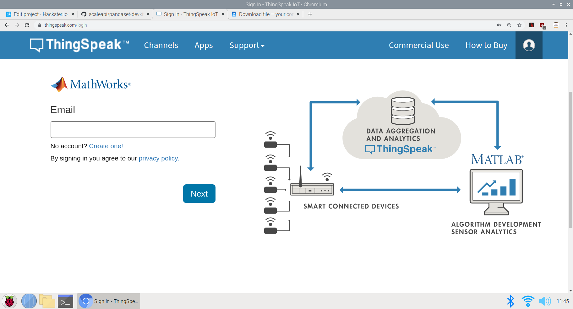
3) Thingspeak:
ThingSpeak™ is een IoT-analyseservice waarmee u live gegevensstromen in de cloud kunt aggregeren, visualiseren en analyseren. ThingSpeak biedt directe visualisaties van gegevens die door uw apparaten naar ThingSpeak zijn gepost. Met de mogelijkheid om MATLAB®-code in ThingSpeak uit te voeren, kunt u online analyses uitvoeren en gegevens verwerken zodra deze binnenkomen. ThingSpeak wordt vaak gebruikt voor prototyping en proof-of-concept IoT-systemen waarvoor analyse nodig is.
U kunt gegevens van elk apparaat met internetverbinding rechtstreeks naar ThingSpeak sturen met behulp van een Rest API of MQTT. Bovendien zorgen cloud-to-cloud-integraties met The Things Network, Senet, de Libelium Meshlium-gateway en Particle.io ervoor dat sensorgegevens ThingSpeak bereiken via LoRaWAN® en 4G/3G mobiele verbindingen.
Aan de slag met implementaties:
1e project:aanraakvrij liftsysteem met spraakherkenning TinyML-model op Arduino BLE 33 sense:
Tijdens het woon-werkverkeer maken we meerdere keren per dag gebruik van liften! Een veelgebruikte schakelaar wordt besmet door iedereen die de lift al eerder heeft aangeraakt. Dus besloot ik een aanraakvrije oplossing voor liften te maken die spraakopdrachten gebruikt en zonder het gebruik van IoT of wifi-netwerk, het samenwerkt en de actie uitvoert. Er zijn oplossingen van aanraakvrije liftsystemen geïmplementeerd die gebarenbesturing of ultrasone sensoren gebruiken om handelingen uit te voeren, maar het probleem met deze sensoren is dat ze van een kleinere afstand moeten worden geactiveerd en daarom neemt het risico op aanraking toe. Bovendien zijn deze sensoren zeer gevoelig en worden ze zelfs geactiveerd als kleine voorwerpen in de weg komen en ze activeren. Dienovereenkomstig stelde ik voor om een nauwkeurigere oplossing te creëren met behulp van stemdetectie op de Arduino 33 BLE sense. Dit model heeft twee commando's, ofwel "up" of "omlaag" en verzendt dienovereenkomstig gegevens naar de servo om op de respectieve knoppen op de schakelaar te drukken. Het idee om de gegevens naar servo te sturen om schakelaars te activeren, is omdat een meerderheid van de samenlevingen vooraf gebouwde schakel- en weergavesystemen heeft en dus deze reeds bestaande systemen niet belemmert, dit is gemaakt om een extern hardwaresysteem toe te voegen om de functies te besturen.
De kernlogica die wordt gebruikt om deze functie uit te voeren is:
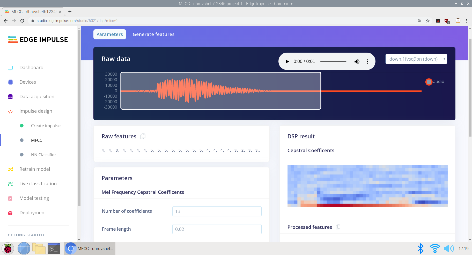
Het model trainen om de "omhoog"- en "spraak"-opdrachten in Edge Impulse Studio te interpreteren
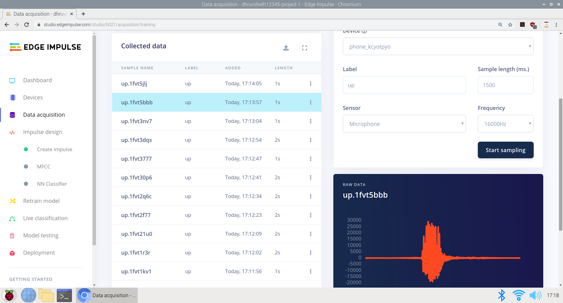
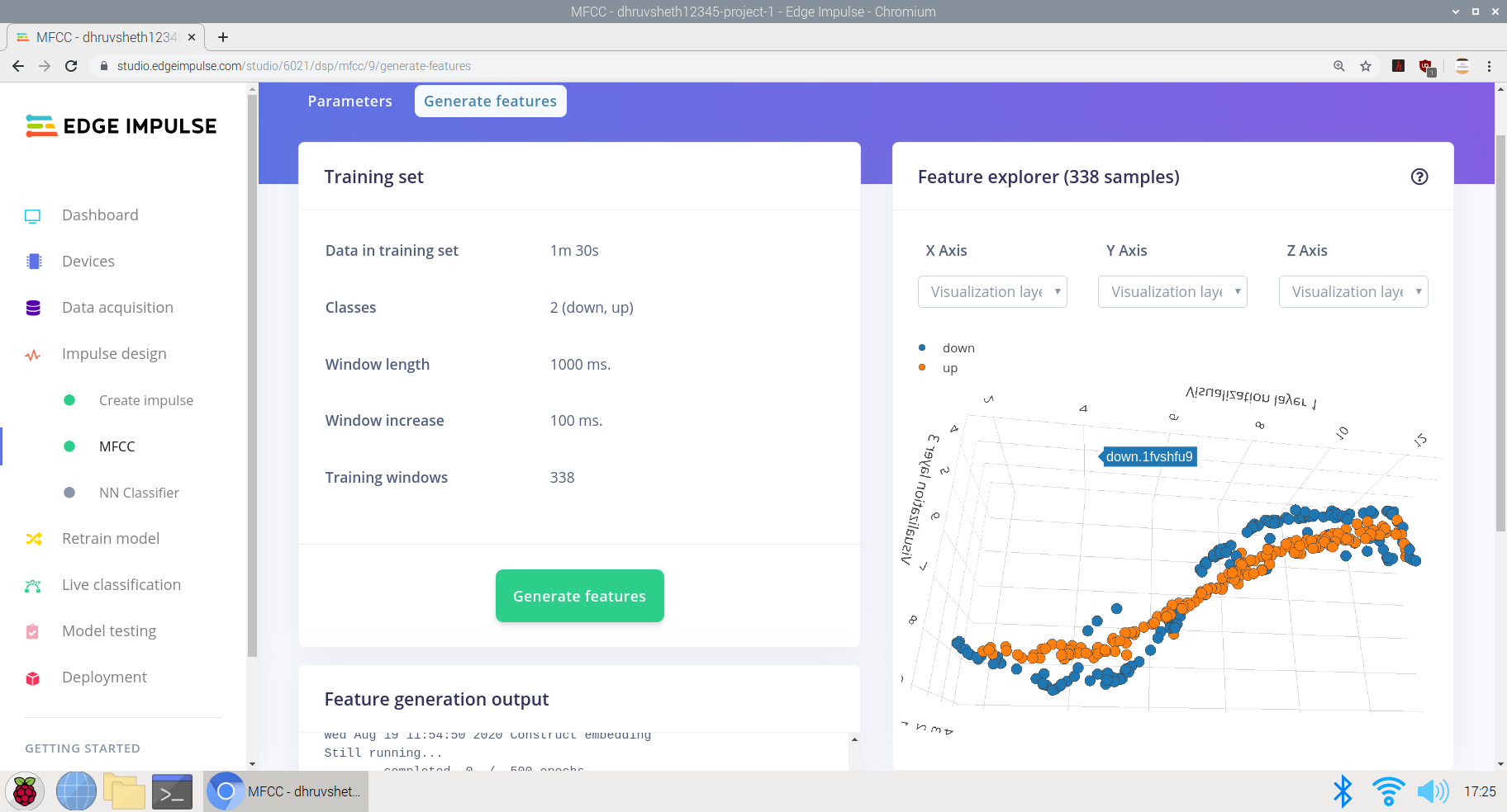
a) Verzamelen van onbewerkte gegevens met trainings- en testgegevenssets. Hier heb ik gegevens verzameld van 1:30 min met elke dataduur van "up" en "down" van 2sec.
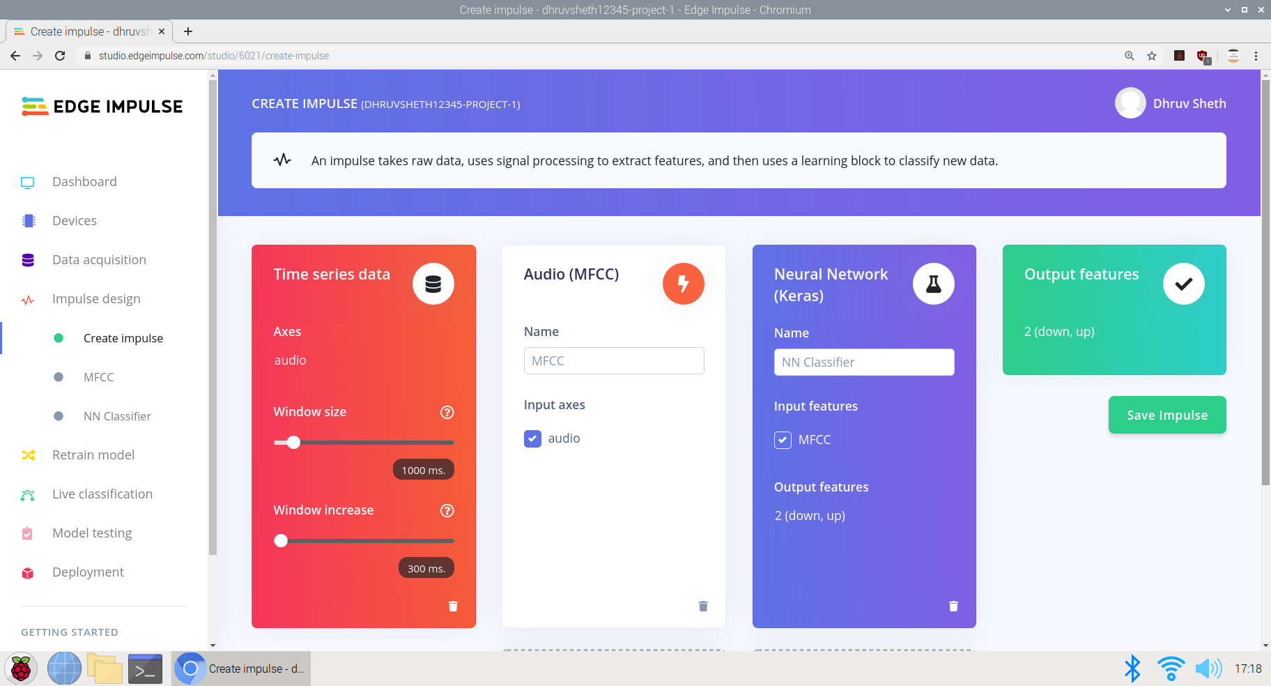
b) Een impuls creëren op basis van de vereiste parameters:
Hier heb ik de venstergrootte ingesteld op 300 ms en training op basis van Keras Neural Network, dat speciaal is bedoeld voor microfoon- en versnellingsmetergegevens.
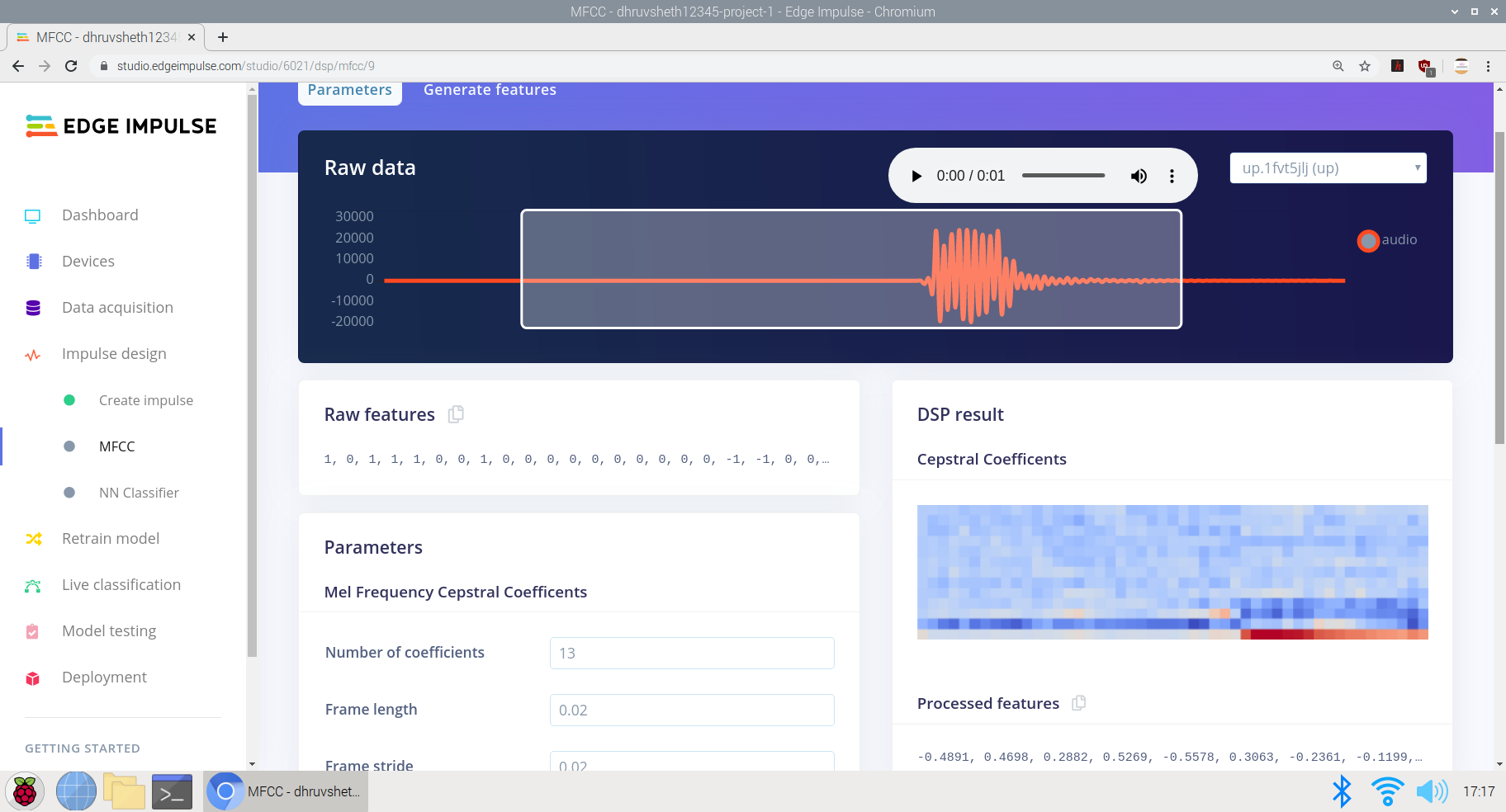
c) Conversie van onbewerkte gegevens naar verwerkte gegevens. Net onder de onbewerkte gegevens kunnen we de functies van de onbewerkte gegevens zien en de verwerkte gegevens worden gezien als DSP-resultaten op basis van cepstrale coëfficiënten.
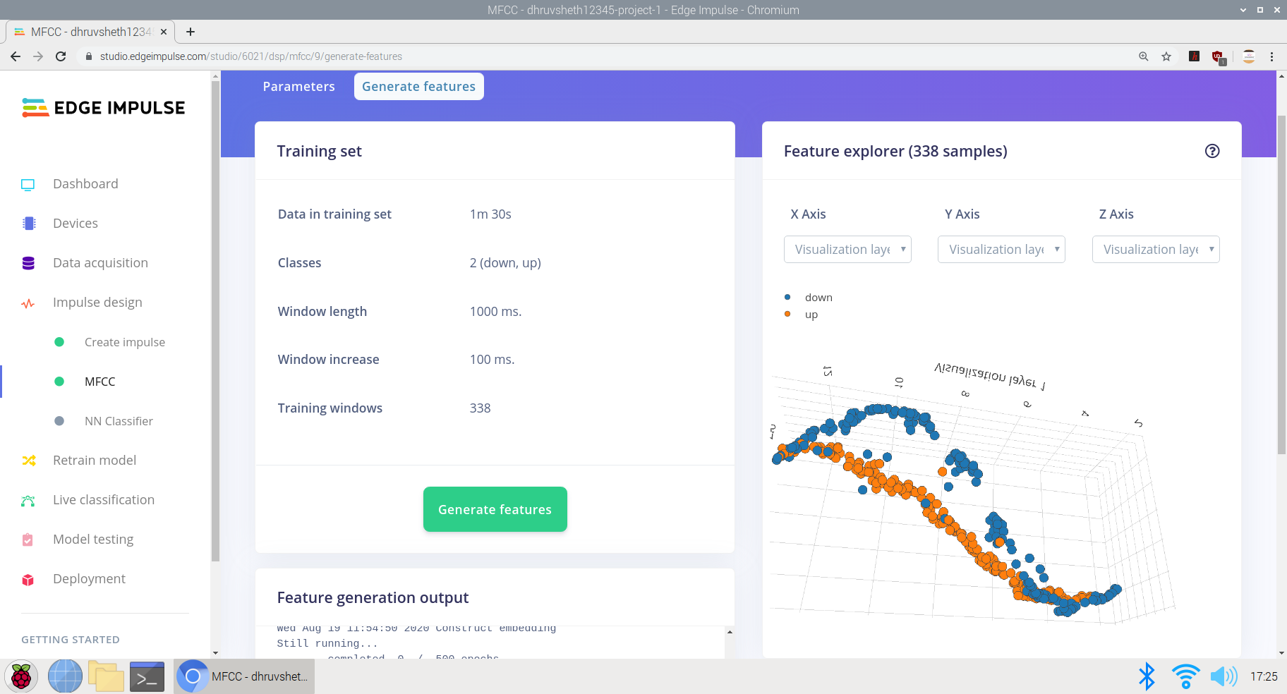
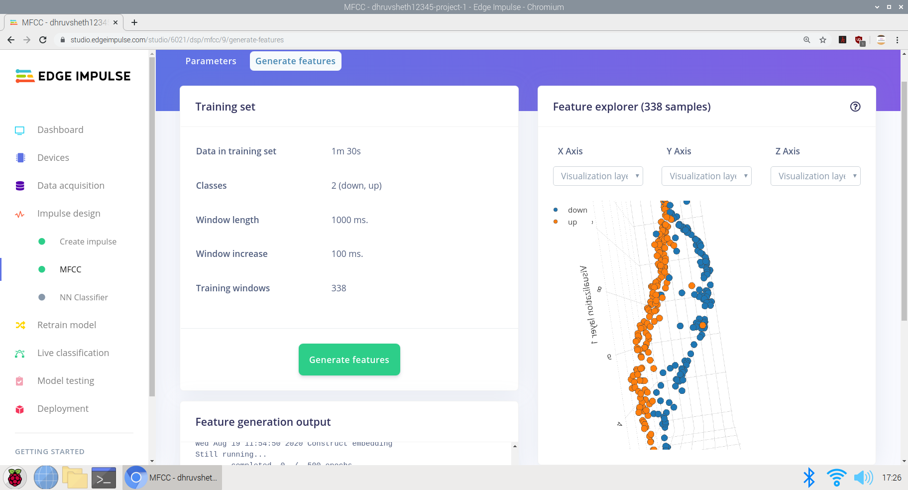
d) De invoergegevens trainen om verwerkte functies te genereren. Ik heb de gegevens met lage en hoge frequentie opgenomen op basis van dezelfde gegevens om de impuls beter te trainen en de spraakherkenning nauwkeurig te maken door deze te trainen op basis van alle soorten stemmen. Hier krijgen we een Feature-uitvoer in een "S"-curve met centrale differentiatie op de x-, y- en z-as.
e) Ten slotte het ontwerpen van een neurale netwerkarchitectuur in Edge Impulse Neural Network Classifier en het trainen van het netwerk.
Hier is de neurale netwerkarchitectuur die is ontworpen voor de gegevensinvoer als volgt:
- Invoerlaag
- Laag hervormen
- 1D convo pool laag (30 neuronen, 5 kernal)
- 1D convo pool laag (10 neuronen, 5 kernal)
- Laag afvlakken
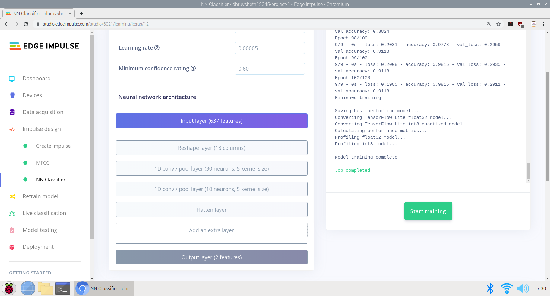
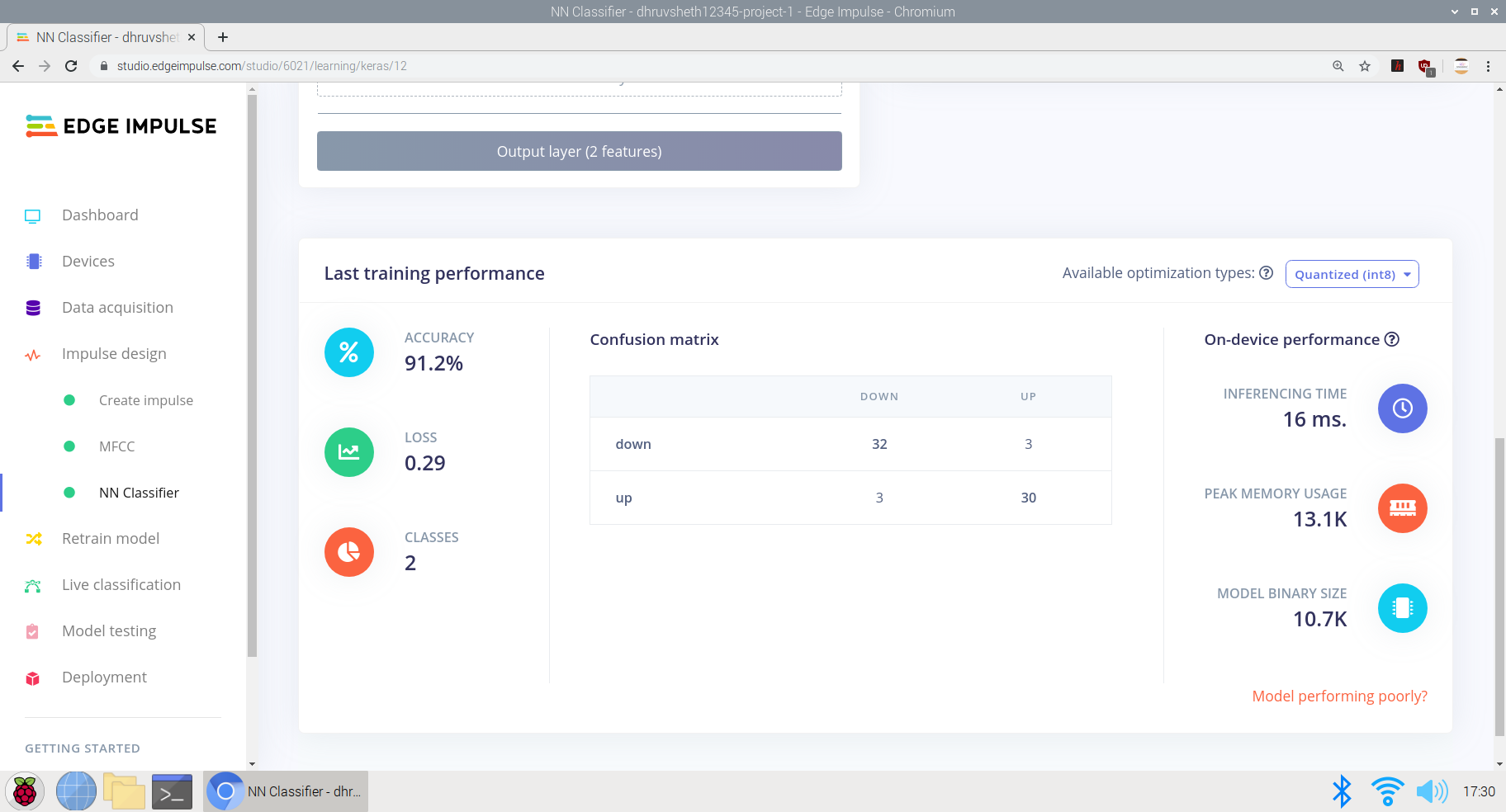
Het model presteerde redelijk goed met een gemiddelde nauwkeurigheid van 91,2% en een verlies van 0,29. Het model werd getraind op 100 trainingscycli (epochs). De verwarringsmatrix ziet er vrij duidelijk en nauwkeurig uit, waarbij de meeste rustgegevens overeenkomen met hun respectievelijke gelabelde klassen.
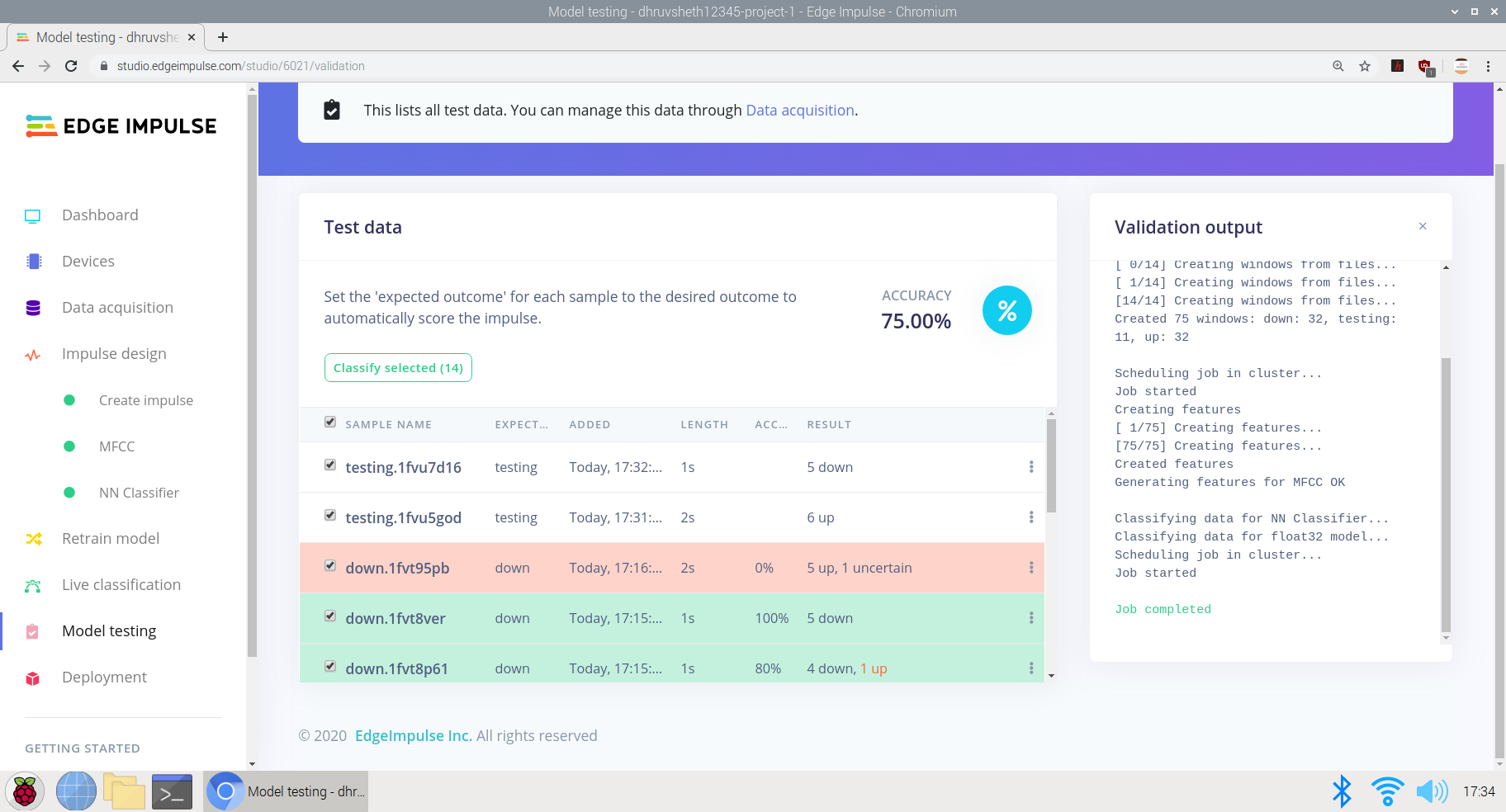
Nadat het model was getraind, heb ik het model getest met testgegevens en livegegevens en het model kreeg een nauwkeurigheid van 75% op basis van testgegevens van 24 seconden

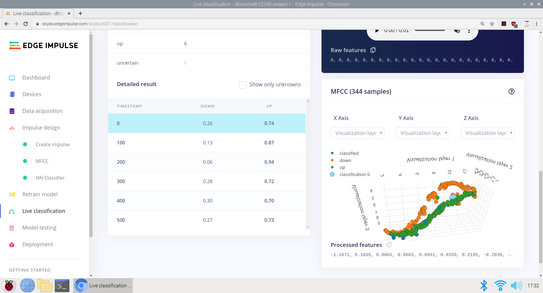
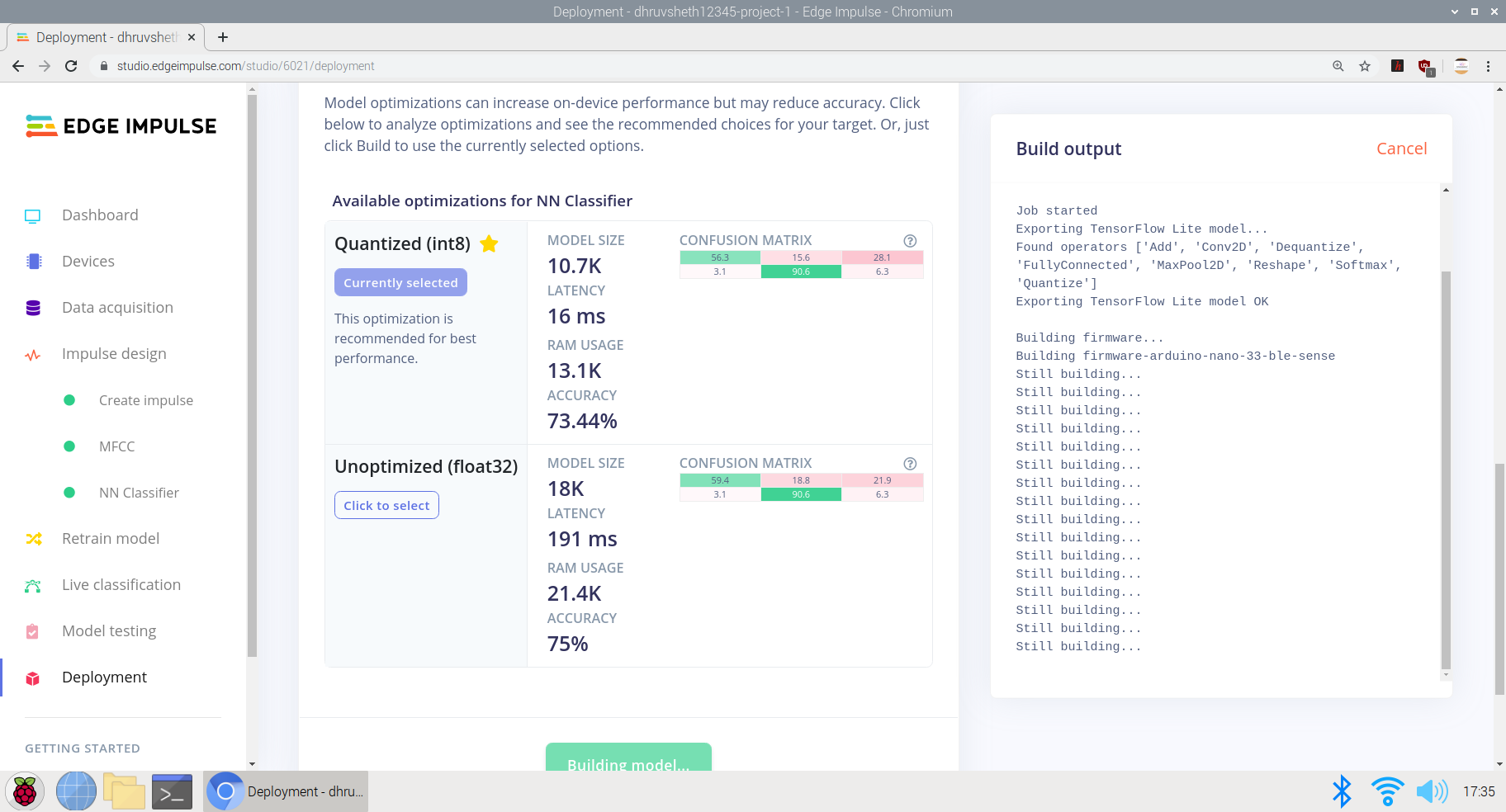
Nadat het model was getraind en een behoorlijke nauwkeurigheid met de logica had gekregen, heb ik het model uiteindelijk als een Arduino-bibliotheek geïmplementeerd en op Arduino 33 BLE sense geïmplementeerd.
Nadat het script klaar was, begon ik het te bewerken op Arduino Web Editor voor het gemak van aanpassing en de uiteindelijke scriptuitvoer die op Arduino 33 BLE Sense kon worden geïmplementeerd, is als volgt:
U kunt het main.ino-bestand op het Arduino Web Editor-platform hier bekijken:
Main-script.ino - Arduino-webeditor
Main-script.ino - Github
Implementeren op Arduino 33 BLE Sense
Op het moment van schrijven is het enige Arduino-bord met een ingebouwde microfoon de Arduino Nano 33 BLE Sense, dus dat is wat we voor deze sectie zullen gebruiken. Als je een ander Arduino-bord gebruikt en je eigen microfoon aansluit, moet je
Op het moment van schrijven is het enige Arduino-bord met een ingebouwde microfoon de Arduino Nano 33 BLE Sense, dus dat is wat we voor deze sectie zullen gebruiken.
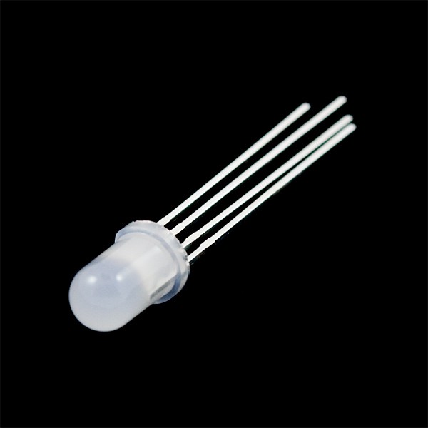
De Arduino Nano 33 BLE Sense heeft ook een ingebouwde LED, die we gebruiken om aan te geven dat een woord is herkend en ook om de servo te besturen om de functie uit te voeren
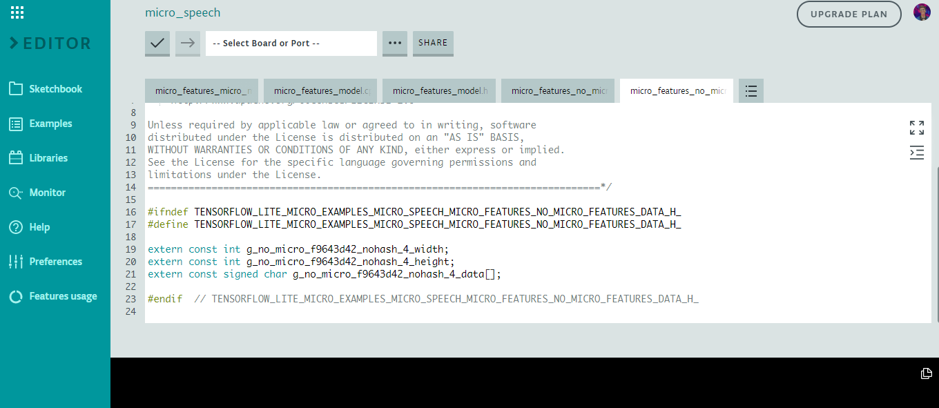
Hier is een fragment van de code voor microfuncties in het model
De logica werkt als volgt voor de reactie op de opdracht:
// Als we een commando horen, laat dan de juiste LED oplichten en zet de juiste servo aan
if (found_command[0] =='up') {
last_command_time =current_time;
digitalWrite (LEDG, LAAG); // Groen voor omhoog, de LED aanzetten met het LOW-commando
servo_7.write(0); // Draai de servo naar 0 graden om op de knop op de lift te klikken wanneer "omhoog" wordt gezegd
delay(100);
digitalWrite(LEDG, HIGH); // De LED uitschakelen na het knipperen van het commando
servo_7.write(180); // servo keert terug naar zijn oorspronkelijke positie, dwz 180 graden
}
// Als we een commando horen, laat dan de juiste LED oplichten en zet de juiste servo aan
if (found_command[0] =='down') {
last_command_time =huidige_time;
digitalWrite(LEDG, LOW); // Groen voor omhoog, de LED aanzetten met het LOW-commando
servo_7.write(0); // Draai de servo naar 0 graden om op de knop op de lift te klikken wanneer "omlaag" wordt gezegd
delay(100);
digitalWrite(LEDG, HIGH); // De LED uitschakelen na het knipperen van het commando
servo_7.write(180); // servo keert terug naar zijn oorspronkelijke positie, d.w.z. 180 graden
}
Het tweede commando is hetzelfde als hierboven, maar draait de servo wanneer het commando "down" wordt gehoord.
Na de trainingsgegevens krijgen we als volgt een getrainde tflite-gegevensset:
Hier gebruiken we de ingebouwde microfoon op de Arduino Nano 33 BLE Sense en het model gebruikt gemiddeld ~24-28Kb van het 256kb flashgeheugen op het Arduino Nano-bord. Dit model is relatief licht in vergelijking met het beeldherkenningsmodel en kan informatie veel sneller verwerken.
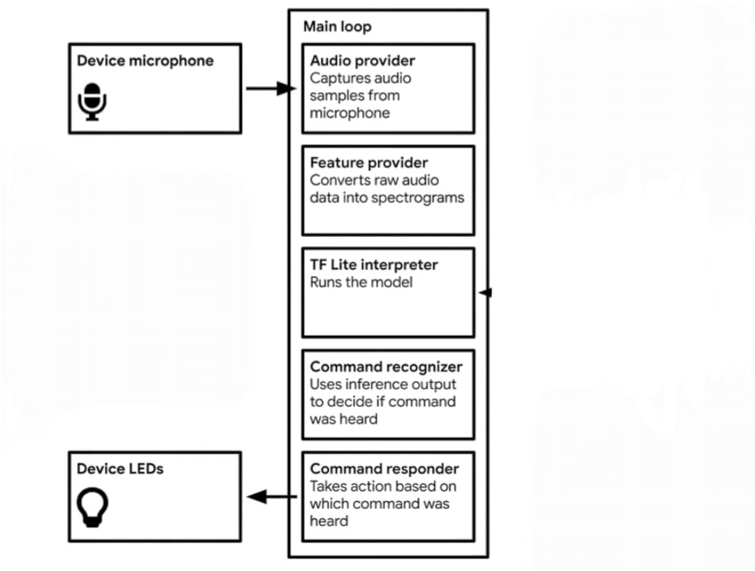
De logica in het spraakherkenningsmodel gaat als volgt:
Gegevens worden vastgelegdNeemt audiovoorbeelden op van microfoonConverteert onbewerkte audiogegevens naar spectrogrammenTflite Interpreter voert het model uitGebruikt inferentie-uitvoer om te beslissen of het commando is gehoordAls het omlaag-commando wordt gehoord, beweegt de servo door op de omlaag-toets op het liftbedieningspaneel te drukken.Als het op-commando hoorbaar is, beweegt de servo door op de opwaartse toets in het liftbedieningspaneel te drukken.
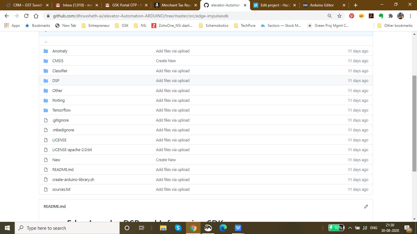
De hierboven zijn de gegevens in de bibliotheek van het getrainde model. De belangrijkste functies zijn opgenomen in het Tensorflow-bestand.
Circuitdiagram voor het project:

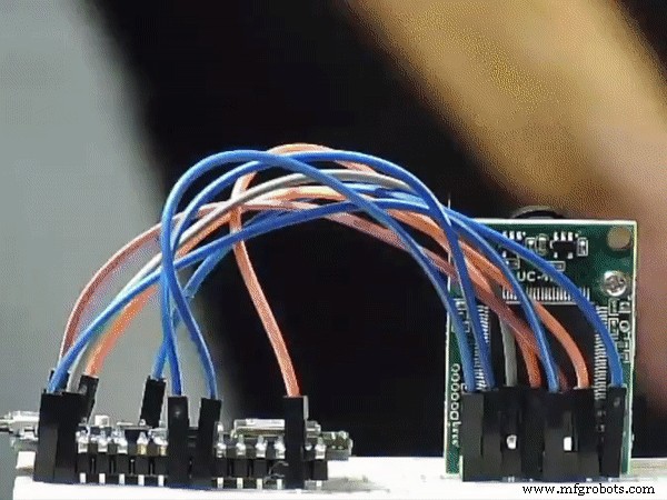
De Arduino Nano 33 BLE Sense gebruikt de ingebouwde microfoon voor het verzamelen van onbewerkte gegevens. Omdat de inferentie op Arduino tijd kost, heb ik een vertraging van 100 milliseconden toegevoegd om de gegevens nauwkeurig te verwerken. Daarom knippert er tussen twee opnamesamples een ingebouwde blauwe led die de reactie aangeeft die moet worden gehoord/uitgesproken tussen de twee led-flitsen.

Dit is een simulatie van de Arduino 33 BLE Sense die het knipperen van de LED laat zien tussen twee succesvolle microfooningangsintervallen
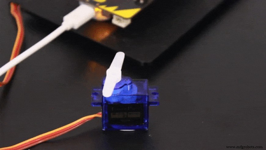
Op basis van de commando-invoer draait de servo dienovereenkomstig
Nu zijn er andere alternatieven voor een aanraakvrij automatiseringssysteem voor liften, zoals het gebruik van ultrasone sensoren of bewegingssensoren, maar beide hebben hun eigen gebreken, daarom heb ik besloten om het spraakgestuurde liftautomatiseringssysteem te maken
Gebreken in ultrasone sensoren: Ultrasone sensoren zijn zeer bewegingsgevoelig. Als een object dat in de doorgang beweegt, in het bereik van ultrasone sensoren komt, worden deze geactiveerd. Ultrasone sensoren zijn ook niet nauwkeurig genoeg, soms verwerken deze verkeerde informatie.
Fouten in gebaargestuurde sensoren: Deze sensoren zijn nauwkeuriger dan ultrasone sensoren, maar ze moeten van een kleinere afstand worden geactiveerd. Dit verhoogt het risico op aanraking tussen handen en het liftpaneel.
Het spraakgestuurde liftpaneel is echter nauwkeuriger dan de bovenstaande twee oplossingen en kan vanaf een grotere afstand worden geactiveerd dan de ultrasone en gebarensensor.
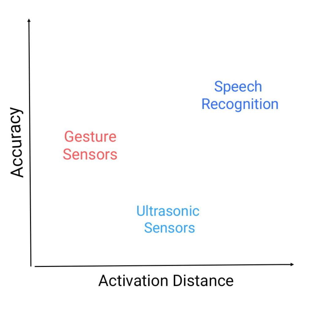
Hier is een grafiek van nauwkeurigheid versus activeringsafstand en waar deze sensoren staan.
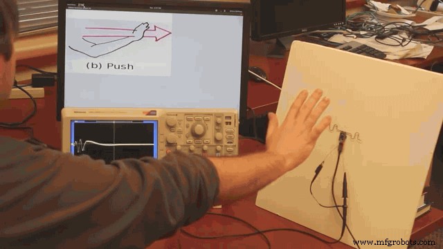
Dit toont de afstand die nodig is om de bewegingssensor te activeren. Aangezien deze afstand echt kleiner blijkt te zijn, is de mate van besmetting hoog
vervolgens gaan we verder met het tweede deelproject van het hoofdproject
2e project:slim intercomsysteem met gezichtsherkenning en TinyML:
CDC heeft zijn site bijgewerkt en een persbericht uitgegeven waarin staat dat indirect contact vanaf een oppervlak dat besmet is met het nieuwe coronavirus - bekend als fomite-overdracht - een mogelijke manier is om het nieuwe coronavirus op te lopen.
Onderzoek heeft uitgewezen dat het nieuwe coronavirus tot drie dagen kan aanhouden op plastic en metalen oppervlakken en op karton tot 24 uur. Er moeten echter veel dingen gebeuren voordat iemand Covid-19 kan oplopen door het aanraken van een besmet oppervlak.
Ten eerste moet een persoon in contact komen met voldoende van het virus om daadwerkelijk een infectie te veroorzaken. Om bijvoorbeeld met het influenzavirus te worden geïnfecteerd, moeten miljoenen exemplaren van het virus vanaf een oppervlak iemands gezicht bereiken, maar er zijn slechts een paar duizend exemplaren nodig wanneer het virus rechtstreeks in de longen terechtkomt, de New York Tijden rapporten.
Als een persoon een oppervlak met grote sporen van het virus aanraakt, moet hij genoeg van het virus oppikken en vervolgens zijn ogen, neus of mond aanraken. Daarom zeggen volksgezondheidsdeskundigen dat het zo belangrijk is om aanraking te vermijden oppervlakken te vaak en beperken het aanraken van verontreinigde objecten of objecten die vaak worden aangeraakt.
Het COVID-19-virus verspreidt zich over de hele wereld. Zelfs als het uiteindelijk verdwijnt, zullen mensen een gevoeligheid hebben ontwikkeld om dingen in het openbaar aan te raken. Aangezien de meeste intercoms zijn ontworpen om een druk op de knop te vereisen om te bellen, besloot ik dat er contactloze intercomoplossingen nodig waren waarbij mensen niets hoeven aan te raken.
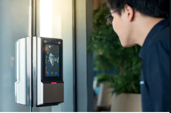
De bovenstaande afbeelding toont een geïmplementeerd intercomsysteem op basis van gezichtsherkenning.
Om het probleem van op aanraking gebaseerde systemen op te lossen, is het noodzakelijk om de plaatsen van contact en aanraking te verminderen. In het traditionele systeem van intercoms bestaan ze uit op schakelaars gebaseerde systemen, wanneer ingedrukt, gaat de bel. Om het op aanraking gebaseerde systeem, dat het risico op besmetting van oppervlakken verhoogt, te vernieuwen, heb ik besloten om een aanraakvrij gezichtsherkenningssysteem te bouwen dat wordt geïmplementeerd op de Arduino 33 BLE Sense, op basis van tinyML en Tensorflow Lite.
In dit slimme intercomsysteem heb ik het persoonsdetectie-algoritme gebruikt dat is geïmplementeerd op Arduino 33 BLE Sense, dat mensen identificeert en dienovereenkomstig aanbelt met een LED Matrix-display dat "Persoon" aangeeft.
Op weg naar de implementatie van het slimme intercomsysteem:
De volgende software is gebruikt bij het ontwerpen van dit model:
- TensorFlow lite
- Arduino-webeditor
In this person detection model, I have used the Pre-trained TensorFlow Person detection model apt for the project. This pre-trained model consists of three classes out of which the third class is with undefined set of data:
"unused",
"person",
"notperson"
In our model we have the Arducam Mini 2mp plus to carry out image intake and this image data with a decent rate of fps is sent to the Arduino Nano 33 BLE Sense for processing and and classification. Since the Microcontroller is capable of providing 256kb RAM, we change the image size of each image to a standard 96*96 for processing and classification. The Arduino Tensorflow Lite network consists of a deep learning framework as:
- Depthwise Conv_2D
- Conv_2D
- AVERAGE Pool_2D
- Flatten layer
This deep learning framework is used to train the Person detection model.
The following is the most important function defined while processing outputs on the Microcontroller via Arduino_detetction_responder.cpp
// Process the inference results.
 uint8_t person_score =output->data.uint8[kPersonIndex];
 uint8_t no_person_score =output->data.uint8[kNotAPersonIndex];
 RespondToDetection(error_reporter, person_score, no_person_score);
In the following function defining, the person_score , the no_person_score have been defined on the rate of classification of the data.
The Logic works in the Following way:
├── Autonomous Intercom System
├── Arducam Mini 2mp plus
│ ├── Visual data sent to Arduino
├── Arduino 33 BLE Sense
│ ├── if person-score> no_person_score
│ │ ├── Activate the buzzer
│ │ ├── Display "Person" on the LED Matrix
│ │ └── ...Repeat the loop
Adhering to the above logic, The arducam Mini 2mp plus continuously takes in visual data and sends this data to the Arduino 33 BLE Sense to process and classify the the data collected. Once the raw data is converted to processed data, it is then classified as per the data trained. If a person is detected, the Arduino sends a signal to the buzzer to activate and the MAX7219 to display "person". In this way, the logic of the system works.
Functioning and Working of Logic in Code:
The following are the Libraries included in themain.ino code for functioning of the model.
#include

#include "main_functions.h"

#include "detection_responder.h"
#include "image_provider.h"
#include "model_settings.h"
#include "person_detect_model_data.h"
#include "tensorflow/lite/micro/kernels/micro_ops.h"
#include "tensorflow/lite/micro/micro_error_reporter.h"
#include "tensorflow/lite/micro/micro_interpreter.h"
#include "tensorflow/lite/micro/micro_mutable_op_resolver.h"
#include "tensorflow/lite/schema/schema_generated.h"
#include "tensorflow/lite/version.h"
In the following code snippet, the loop is defined and performed. Since this is the main.ino code, it controls the core functioning of the model - used to run the libraries in the model.
void loop() {
 // Get image from provider.
 if (kTfLiteOk !=GetImage(error_reporter, kNumCols, kNumRows, kNumChannels,
 input->data.uint8)) {
 TF_LITE_REPORT_ERROR(error_reporter, "Image capture failed.");
 }

 // Run the model on this input and make sure it succeeds.
 if (kTfLiteOk !=interpreter->Invoke()) {
 TF_LITE_REPORT_ERROR(error_reporter, "Invoke failed.");
 }

 TfLiteTensor* output =interpreter->output(0);

 // Process the inference results.
 uint8_t person_score =output->data.uint8[kPersonIndex];
 uint8_t no_person_score =output->data.uint8[kNotAPersonIndex];
 RespondToDetection(error_reporter, person_score, no_person_score);
}
In the following code snippet, the necessary libraries required to inference the image to be captured is displayed. The images after captured are converted to a 96*96 standardised size which can be interpreted on the arduino board.
Here, the Arducam mini 2mp OV2640 library has been utilised.
This code has been provided in the arduino_image_provider.cpp snippet
#if defined(ARDUINO) &&!defined(ARDUINO_ARDUINO_NANO33BLE)
#define ARDUINO_EXCLUDE_CODE
#endif // defined(ARDUINO) &&!defined(ARDUINO_ARDUINO_NANO33BLE)

#ifndef ARDUINO_EXCLUDE_CODE

// Required by Arducam library
#include
#include
#include
// Arducam library
#include
// JPEGDecoder library
#include

// Checks that the Arducam library has been correctly configured
#if !(defined OV2640_MINI_2MP_PLUS)
#error Please select the hardware platform and camera module in the Arduino/libraries/ArduCAM/memorysaver.h
#endif

// The size of our temporary buffer for holding
// JPEG data received from the Arducam module
#define MAX_JPEG_BYTES 4096
// The pin connected to the Arducam Chip Select
#define CS 7

// Camera library instance
ArduCAM myCAM(OV2640, CS);
// Temporary buffer for holding JPEG data from camera
uint8_t jpeg_buffer[MAX_JPEG_BYTES] ={0};
// Length of the JPEG data currently in the buffer
uint32_t jpeg_length =0;

// Get the camera module ready
TfLiteStatus InitCamera(tflite::ErrorReporter* error_reporter) {
 TF_LITE_REPORT_ERROR(error_reporter, "Attempting to start Arducam");
 // Enable the Wire library
 Wire.begin();
 // Configure the CS pin
 pinMode(CS, OUTPUT);
 digitalWrite(CS, HIGH);
 // initialize SPI
 SPI.begin();
 // Reset the CPLD
 myCAM.write_reg(0x07, 0x80);
 delay(100);
 myCAM.write_reg(0x07, 0x00);
 delay(100);
 // Test whether we can communicate with Arducam via SPI
 myCAM.write_reg(ARDUCHIP_TEST1, 0x55);
 uint8_t test;
 test =myCAM.read_reg(ARDUCHIP_TEST1);
 if (test !=0x55) {
 TF_LITE_REPORT_ERROR(error_reporter, "Can't communicate with Arducam");
 delay(1000);
 return kTfLiteError;
 }
The following code is the Arduino_detection_responder.cpp code which controls the main output of the model. Here, we have taken into consideration, the classification score as defined in the main.ino code and according to the confidence of person score, I am providing outputs.
// Switch on the green LED when a person is detected,
 // the red when no person is detected
 if (person_score> no_person_score) {
 digitalWrite(LEDG, LOW); // if a person is detected at the door, the buzzer switches on
 digitalWrite(LEDR, HIGH); // the led matrix in the house displays "person"
 digitalWrite(5, LOW);
 myDisplay.setTextAlignment(PA_CENTER);
 myDisplay.print("Person");
 delay(100);
 } else {
 digitalWrite(LEDG, HIGH);
 digitalWrite(LEDR, LOW);
 }

 TF_LITE_REPORT_ERROR(error_reporter, "Person score:%d No person score:%d",
 person_score, no_person_score);
}

#endif // ARDUINO_EXCLUDE_CODE
Working of the Firmware:

This is the complete setup of the firmware designed on Fritzing.
This simulation shows the capture of data by the Arducam and similarly classification of this data by Arduino 33 BLE Sense
This model comprises of the following firmware used:
- Arduino 33 BLE sense - Used to process the data gathered, classifies the data processes, sends the command according to the logic fed.
- Buzzer - For Alerting when a person is at the door.
- Arducam Mini 2mp plus - Continuous Raw data image accumulation from source.
- Adafruit lithium ion charger - Used to deliver charge through the lithium battery
- Lithium ion Battery - power source
- MAX7219 4 in 1 display - Used for displaying "person" on the display screen.
Additional Features: Using the existing intercom system, it is possible to add a servo to push the button to view the person who is standing at the door as shown in the image:
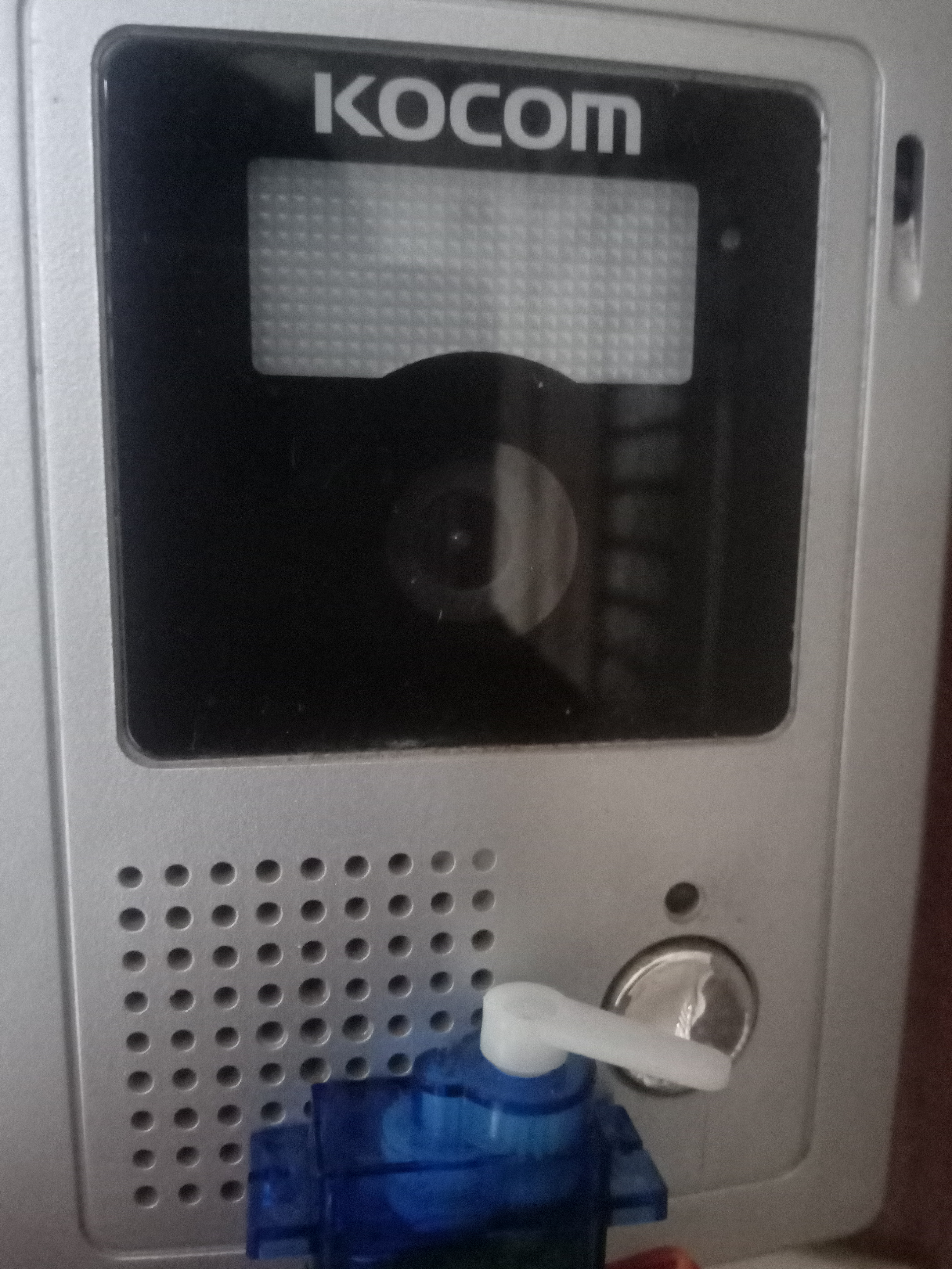

This can be an additional setup in intercom system to switch on video when a person is detected. However, this additional system has to be deployed on the Existing Intercom system.
Additional code added to the existing code:
// Switch on the green LED when a person is detected,
 // the red when no person is detected
 if (person_score> no_person_score) {
 digitalWrite(LEDG, LOW); // if a person is detected at the door, the buzzer switches on
 digitalWrite(LEDR, HIGH); // the led matrix in the house displays "person"
 digitalWrite(5, LOW);
 myDisplay.setTextAlignment(PA_CENTER);
 myDisplay.print("Person");
 servo_8.write(0); // this switches on the intercom by rotating servo
 delay(500);
 servo_8.write(180); // this switches off the intercom by rotating servo
 delay(100);
 } else {
 digitalWrite(LEDG, HIGH);
 digitalWrite(LEDR, LOW);
I have added an additional function which rotates the servo to switch on the existing intercom and then switches back to its original place.
3rd Project:Autonomous IoT based person temperature sensing automation:
The temperature sensor for Arduino is a fundamental element when we want to measure the temperature of a process or of the human body.
The temperature sensor with Arduino must be in contact or close to receive and measure the heat level. That's how thermometers work.
These devices are extremely used to measure the body temperature of sick people, as the temperature is one of the first factors that change in the human body, when there is an abnormality or disease.
One of the diseases that alter the temperature of the human body is COVID 19. Therefore, we present the main symptoms:
- Cough
- Tiredness
- Difficulty breathing (Severe cases)
- Fever
Fever is a symptom whose main characteristic is an increase in body temperature. In this disease, we need to constantly monitor these symptoms.
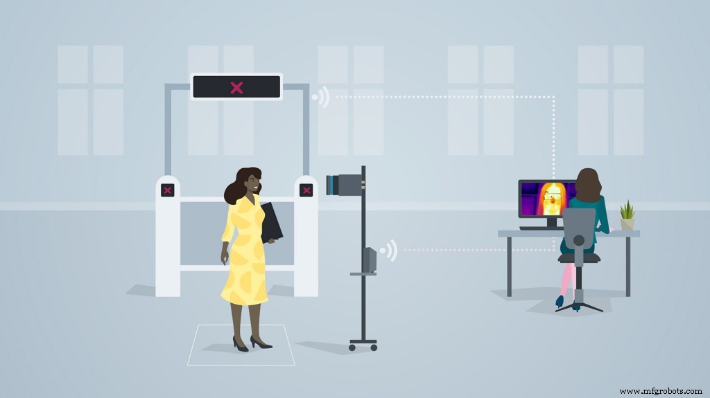
The retail market has been hit with a great impact due to the pandemic. After the malls and supermarkets have re-begun, it is necessary to ensure safety of all the customers who have entered the premises. For this purpose, manual temperature checking techniques have been set up. This increases the labour and also a risk of contact between the person checking the temperature and the person whose temperature is being check. This is demonstrated as follows:
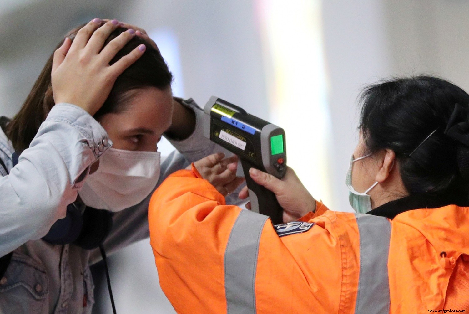
This image shows the close contact or less social distance maintained between the two persons.
There is a second flaw which is faced in manual temperature checking system:
For the temperatures which have been checked, the data of these recordings is not stored or not synchronised with an external device for monitoring the temperatures measured.
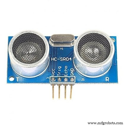
Taking in all these cons into consideration, I've come up with an Arduino based IoT solution deployed on the Arduino MKR WiFi 1010. The temperatures are measured using the Adafruit AMG8833 temperature module. Whenever a person is detected on the gate, the ultrasonic sensors, send the information to the Arduino MKR WiFi 1010 to give a command to the AMG 8833 module to take in temperature data. The module captures the data accurately and the data is projected on an IoT dashboard in real time. If an abnormal temperature reading of a person is detected, an alarm is set on so that the mall security and staff can immediately investigate upon the matter. The data collected is each given a timestamp and can be viewed on the ThingSpeak dashboard the temperature recording vs Time graph for each data.
Similarly, it can be also traced on which days and which time range, does the supermarket or the mall show abnormal temperature readings and more security measures can be implemented accordingly.
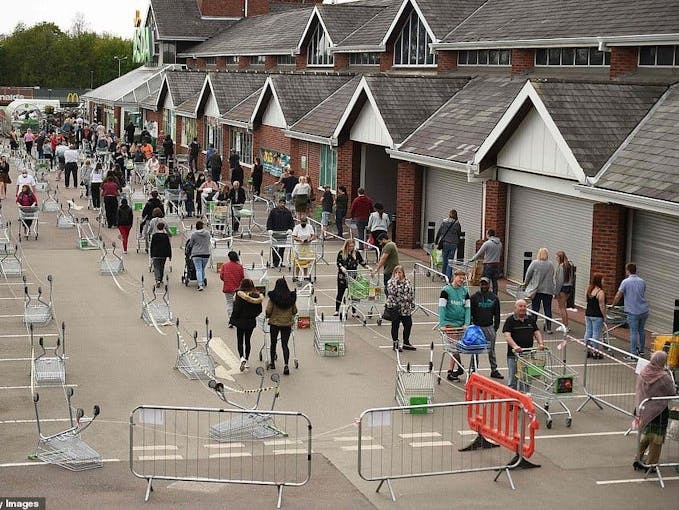
The below image shows wherethe setup can be embedded(The area where the setup can be installed)
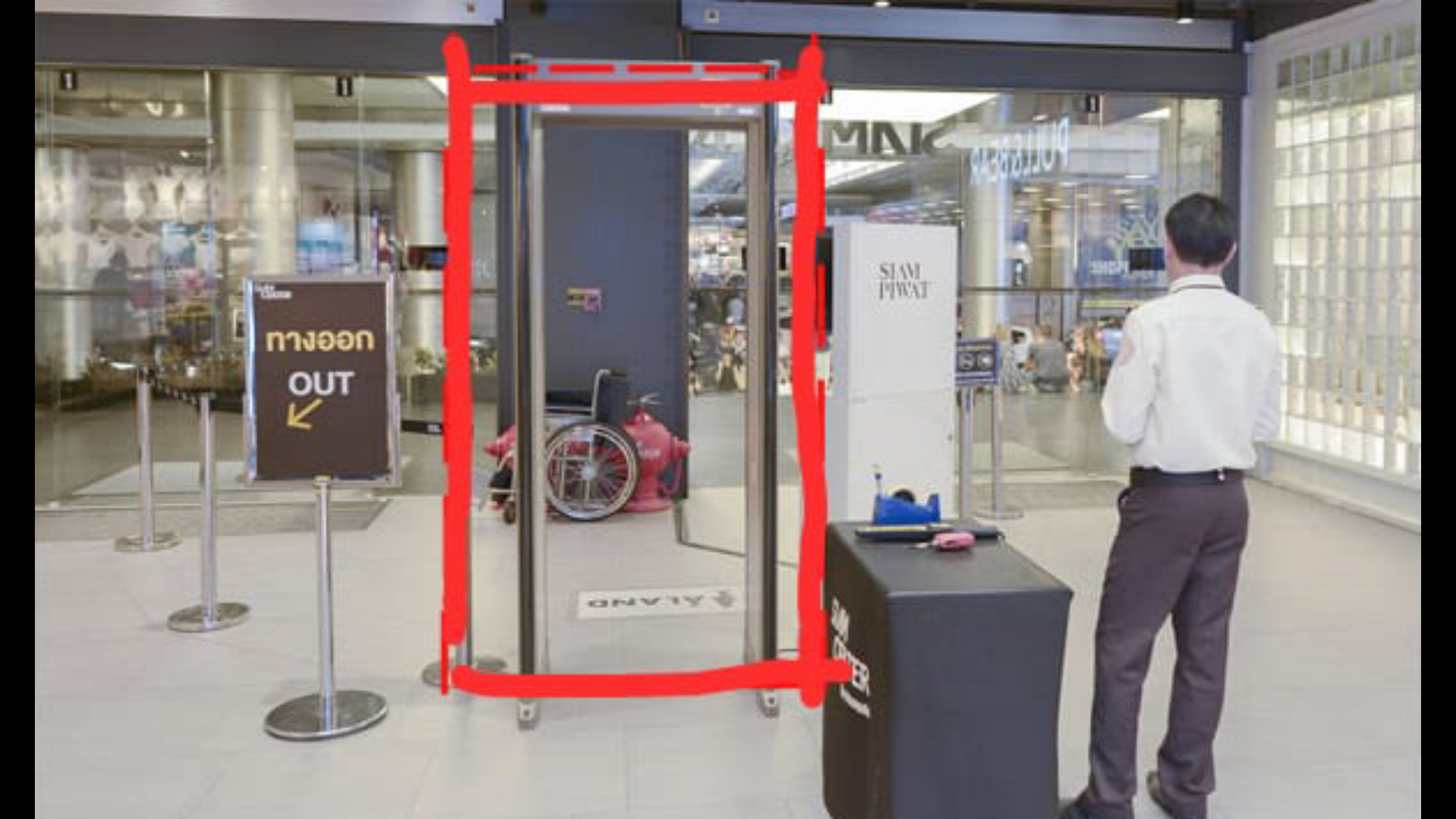
On the entry checking gate, HC-SR04 Ultrasonic Sensors can be installed which detects the entry of a person and sends the command to the Arduino MKR WiFi 1010 if the person is detected in a 20cm range. The Arduino microcontroller passes on the same command to the AMG 8833 temperature module to read the temperature of the person. This complete process takes time from the Ultrasonic Sensor detecting the person, to sending the command to the temperature module to detect the temperature. Hence, in order to sync with the delay, the temperature module is attached a bit far way from the Ultrasonic sensor.
Whenever a person walks in, the gate is opened ( Here, in the prototype, we are using the servo to function as a gate, but in further implementation of the project, the servo will be replaced by a heavy duty gate motor and controlled via motor driver, wherein the Arduino will be sending commands ). The temperature reading of the person is taken and this reading is sent to the thingspeak IoT dashboard in real time via the Arduino WiFi 1010. For this, an active wifi connection is required in the mall premises which is usually available in most of the cases. According to Research, the body temperature of a person with fever is approximately 38.1C which is 104F. Hence, if the Temperature module detects a temperature above this threshold, the servo turns 180Degrees and the Buzzer goes on to alarm people about the Person. Similarly, security and other mall staff can reach the area in time to control the situation when such a case happens.
The Logic works in the Following way:
├── PersonTemperature Detection MKR WiFi 1010
├── HC-Sr04 Ultrasonic sensor
│ ├── Person Detection
│ │ ├── If( Person distance =20) ,send command
├── Arduino
│ ├── if Ultrasonic sensor Sends a command;
│ │ ├── Open the gate - Servo(0)
│ │ ├── Activate the AMG8833 to take readings
│ │ ├── Send the Readings to ThingSpeak Dashboard
│ │ | ├── If Temperature> 38.1C
│ │ │ | ├── Close the gate - servo(180)
│ │ │ │ ├── Activate the Buzzer
│ │ └── ...Repeat the loop
In this way, the complete Logic of the Temperature Monitor Functions.
The circuit Diagram for the Temperature Model is given as follows:
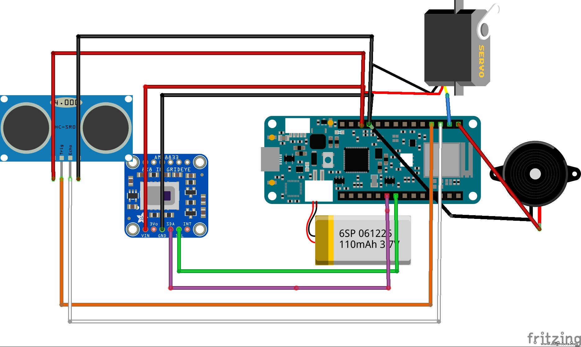
This is the complete Firmware and setup used in the project
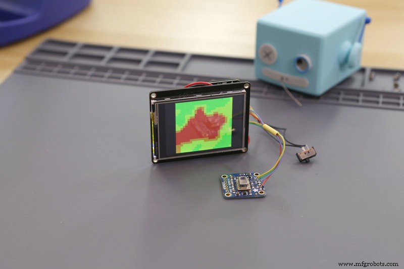
This simulation shows the data type captured by the AMG 8833 Thermal Cam and this data is sent to the Arduino MKR WiFi 1010 to transfer commands
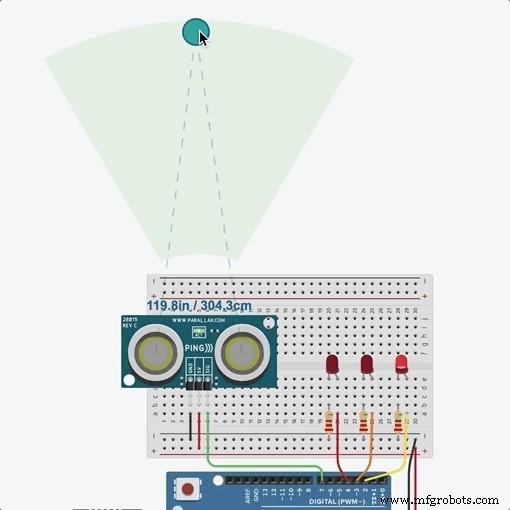
This simulation shows the distance captured by ultrasonic Sensor and this command is sent to the Arduino MKR WiFi to activate the AMG 8833 thermal sensor
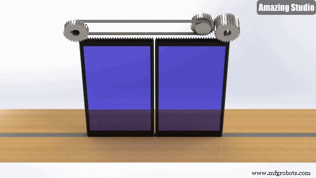
Instead of a servo based door opening system, I will be implementing a command system using motor driver to automate door sliding opening system as follows:
Setting up the IoT Dashboard:
Using Thingsepak IoT Dashboard Setup:
ThingSpeak™ is an IoT analytics service that allows you to aggregate, visualize, and analyze live data streams in the cloud. ThingSpeak provides instant visualizations of data posted by your devices to ThingSpeak. With the ability to execute MATLAB® code in ThingSpeak, you can perform online analysis and process data as it comes in. ThingSpeak is often used for prototyping and proof-of-concept IoT systems that require analytics.
Since, ThingSpeak was easy to setup and use, I preffered to go with that dashboard. This interface allows the user to share the dashboard the security or staff department in the mall so that they can continuously monitor the people visiting the mall, and similarly impose restrictions at certain times when they feel the temperature risk is higher.
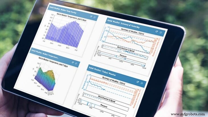
The above image represents the versatility of the thingspeak dashboard and the creative visualisations potrayed.
Logic used in the ThingSpeak IoT data collection process
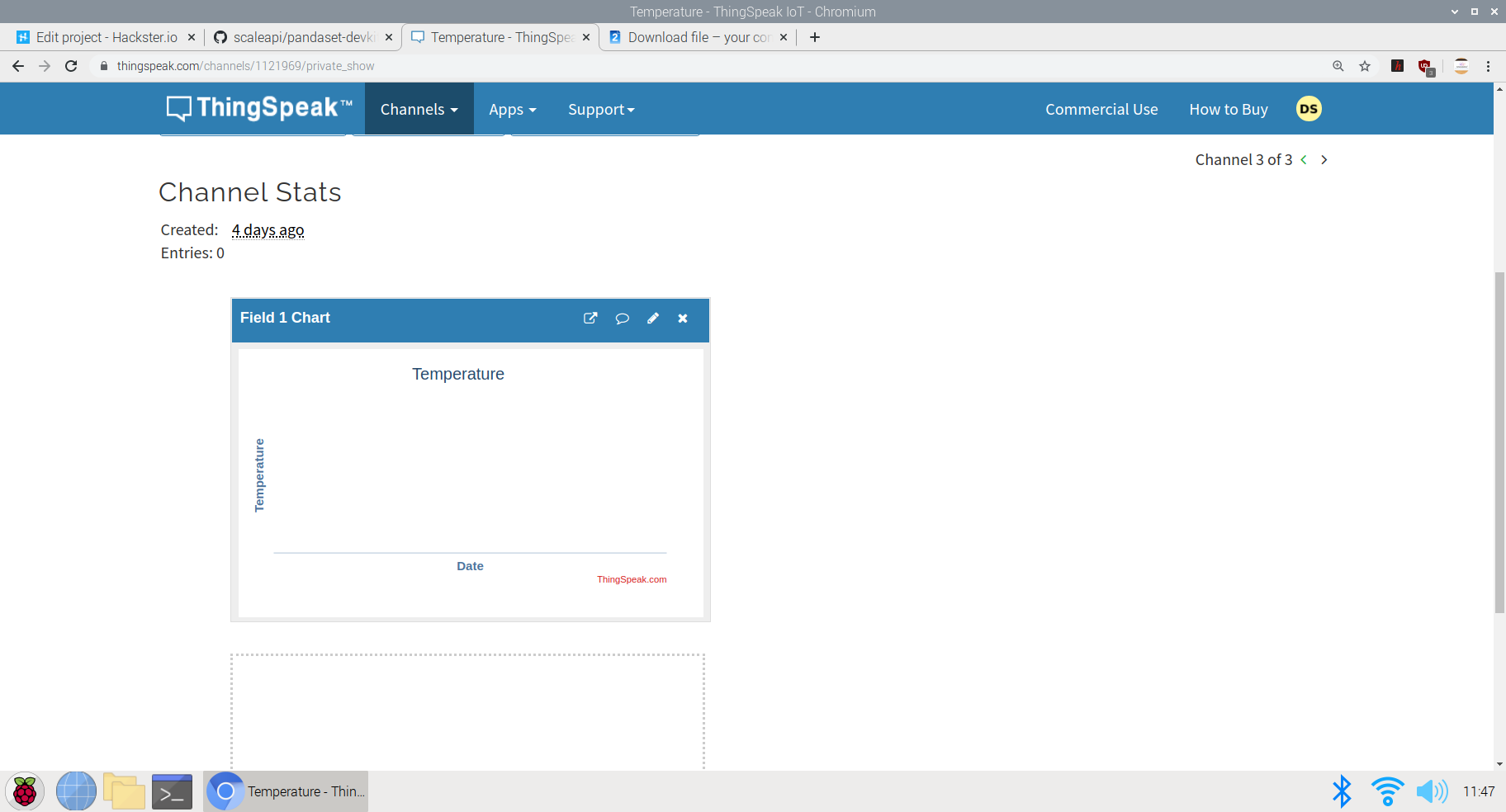
This image shows the creation of visualisations in different channels. Here, I've created a Temperature vs Time Graph in the visualisation section. The data collected by the AMG8833 sensor will be each allocated a timestamp and will be plotted on the graph to see the time for which each data is captured.
The data collected can be viewed in real time on the Public Dashboard here; ThingSpeak Temperature Dashboard
Similarly, this plot can be integrated cumulatively to a single Dashboard made open to the visitors of the mall to view the temperature data before entering the mall. If the visitors find an abnormal temperature reading at a particular day, they can prefer not to go to the supermarket or mall at that day to be safe,
The visualisation Integration data chart:
This chart can be embedded at a single dashboard with the readings of the charts of other malls and supermarkets in the particular area and hence, a unique visitor can check which mall is performing better than other mall in terms of safety and can prefer going to the mall where safety guidelines are followed and the people entering are not diagnosed with fever. This can help the Government help establish safety and trust within the people along with the re-opening of malls and retail sectors
The code of the following project can be either viewed in Github or in the Arduino Web editor here; Temperature-Model-code
The logic in the code goes as follows:
#include
#include
#include
#include ESP32_Servo.h
#include
#include
Servo servo1;
int trigPin =9;
int echoPin =8;
long distance;
long duration;
WiFiMulti WiFiMulti;
const char* ssid ="JioFiber-tcz5n"; // Your SSID (Name of your WiFi) - This is a dummy name, enter your wifi ssid here
const char* password ="**********"; //I have not mentioned the password here, while running the cript, you may mention your pwd
const char* host ="api.thingspeak.com/1121969";
String api_key ="8LNG46XKJEJC89FE"; // Your API Key provied by thingspeak
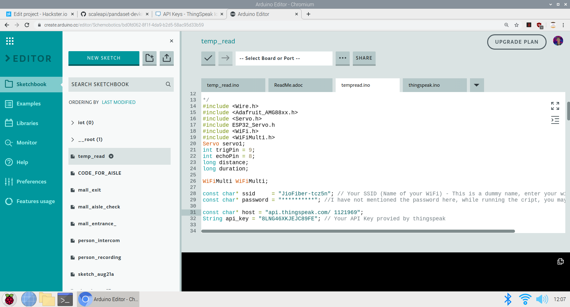
Adafruit_AMG88xx amg; Here, I have defined some of the Libraries and Firmware along with the required setup for the WiFi host and the API-Key for the temperature dashboard on thingspeak
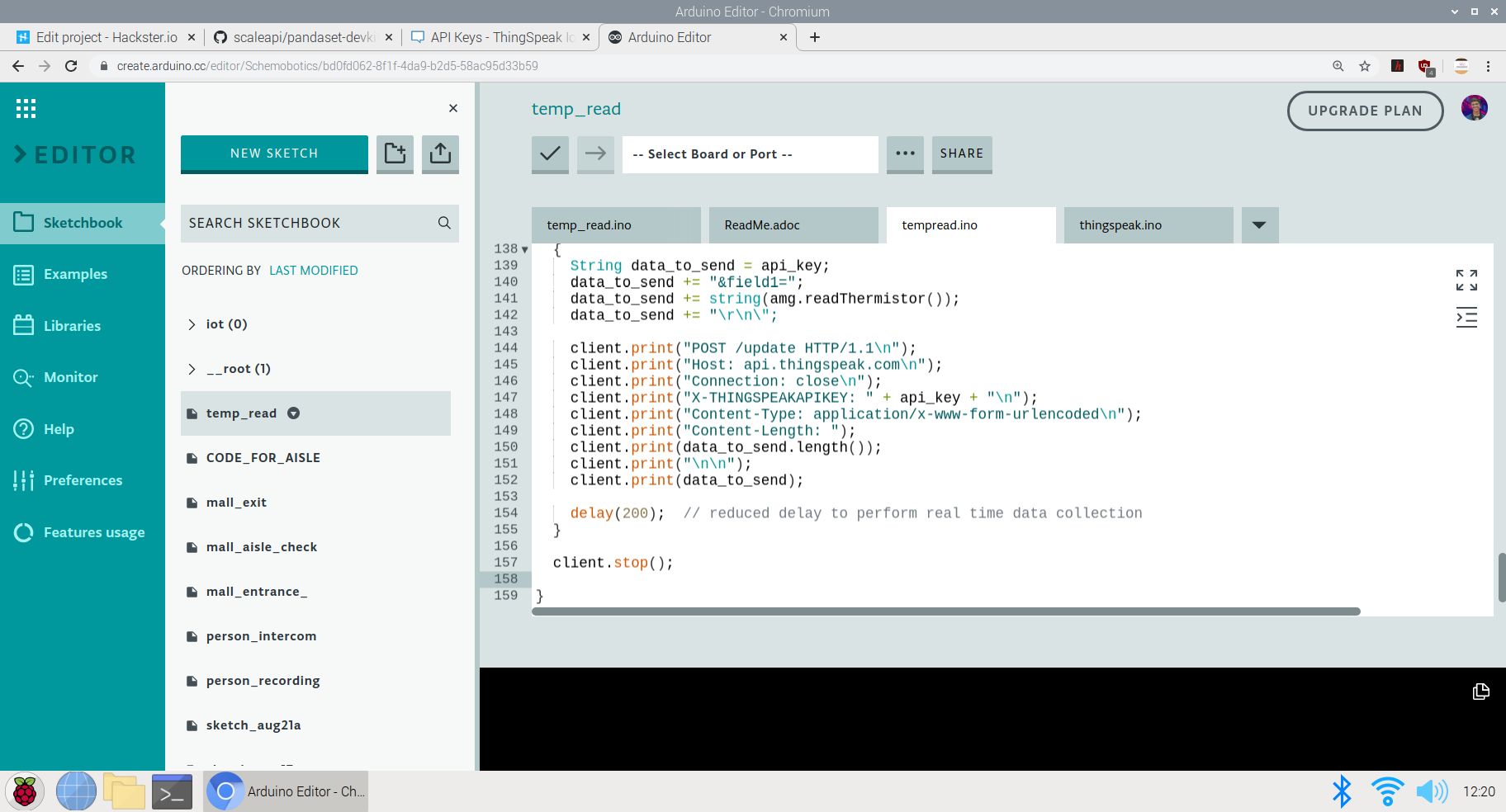
Here's an image of the Code in progress:
The next part of the code is Setting up the required components before the actual loop begins:
These are the prerequisites before looping the actual code. I have defined the Servo pin and the Ultrasonic sensors while also begun the testing of the AMG 8833 to see if it can read data or if its connected
void setup()
{
 Serial.begin(9600);
servo1.attach(7);
 pinMode(trigPin, OUTPUT);
 pinMode(echoPin, INPUT);// put your setup code here, to run once:
}


{
 Connect_to_Wifi();
 Serial.println(F("AMG88xx test"));

 bool status;

 // default settings
 status =amg.begin();
 if (!status) {
 Serial.println("Could not find a valid AMG88xx sensor, check wiring!");
 while (1);
 }

 Serial.println("-- Thermistor Test --");

 Serial.println();

 delay(100); // let sensor boot up
}
The next part is the Void Loop where the complete function is carried out. Here, Initially I have set the gate to open to allow the entry of each person. The AMG 8833 performs data collection and reads the temperature of the people coming inside. If the temperature is higher than the expected threshold, the gate is closed and an alarm(buzzer) is set on to alert people and not allow the entry of the person
void loop()
ultra();
 servo1.write(0);
 if(distance <=20){
 Serial.print("Thermistor Temperature =");
 Serial.print(amg.readThermistor());
 Serial.println(" *C");

 Serial.println();
 // call function to send data to Thingspeak
 Send_Data();
 //delay
 delay(50);

 if(amg.readThermistor()> 38.1) // if a person with fever is detetcted, he is not allowed to enter
 // a person with fever has an avg body temperature of 38.1degree celsius
 servo1.write(180);
 digitalWrite(6, HIGH); //Turns on the buzzer to alarm people
 }
The last part is sending the data to the ThingSpeak Dashboard:
Here, since I have only one field in the channel, all the data will be sent to that field. The captured, amg.readThermistor() data is sent to the dashboard.
void Send_Data()
{

 Serial.println("Prepare to send data");

 // Use WiFiClient class to create TCP connections
 WiFiClient client;

 const int httpPort =80;

 if (!client.connect(host, httpPort)) {
 Serial.println("connection failed");
 return;
 }
 else
 {
 String data_to_send =api_key;
 data_to_send +="&field1=";
 data_to_send +=string(amg.readThermistor());
 data_to_send +="\r\n\";

 client.print("POST /update HTTP/1.1\n");
 client.print("Host:api.thingspeak.com\n");
 client.print("Connection:close\n");
 client.print("X-THINGSPEAKAPIKEY:" + api_key + "\n");
 client.print("Content-Type:application/x-www-form-urlencoded\n");
 client.print("Content-Length:");
 client.print(data_to_send.length());
 client.print("\n\n");
 client.print(data_to_send);

 delay(200); // reduced delay to perform real time data collection
 }

 client.stop();

} 
This ends the code section of the project and we move on to explanation of the use and GO TO MARKET part of the project
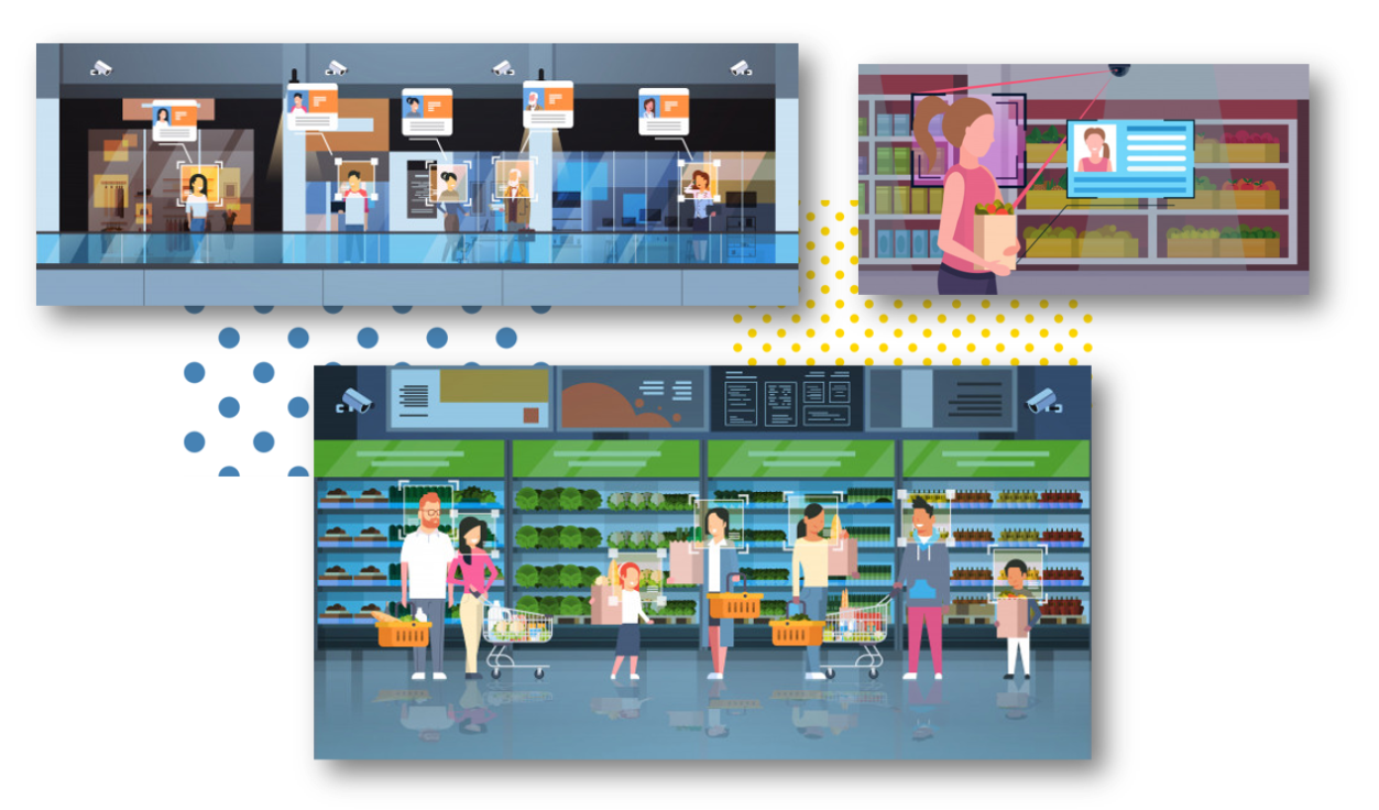
The above image shows the implementation of the methodology and model in supermarkets and malls.
GO TO MARKET &PRACTICALITY:
- Malls and Supermarkets can use this to identify Abnormal Temperature data and this data can be observed even for a certain day at a certain point of time.
- Implement Strategies using this data to ensure Safety and Compliance.
- Decrease Labour and automate Temperature Monitoring Process
- Offer Dashboard to the visitors to monitor if the mall is safe and and accordingly visit the mall at the safest point of time.
- This product can be used to ensure the visitors that the mall is a safe place and hence, can increase the sales and visits following Government guidelines
- Companies offering IoT based solutions can invest in this product for mass production and distribution.
- The more the supermarkets using this product, the more the access to data to the government and more the choice to customers to select the preferable safest place in their locality.
- Comparatively affordable solution as compared to manual temperature monitoring as it decreases the labour cost + decreases the rate of infection when compared to manual monitoring where the person taking temperature has to be close to the visitor to capture the temperature.
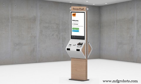
4th Project:TinyML &IoT based queue monitoring and establishing system deployed on the Arduino 33 BLE Sense:
Just as the mall and the retail sector has opened, queue management in malls and supermarkets has become a big problem. Due to the pandemic, restricting only a certain amount of people to go inside the mall has has to be followed by the malls to ensure safety compliance. But this is done manually which increases labour work. Also the data for the number of people inside the mall at a given point of time is not available to the visitors of the mall. If this data would have been made available to the the visitors of the mall, it would increase the percentage of people visiting the mall.
Trying to run a shop or a service during the ongoing Corona crisis is certainly a challenge. Serving customers while keeping them and employees safe is tricky, but digital queuing can help a lot in this regard. The technologies behind virtual queues are not entirely new; the call for social distancing just highlights some of the many benefits they offer.
Most countries have introduced legal measures to combat the spread of COVID-19. To ensure customer satisfaction whilst adhering to the new regulations, one thing is for sure:long queues and crowded lobbies need to go. Digital queuing (also referred to as virtual or remote queuing) technology allows businesses to serve their customers in a timely manner while they stay out of harm’s way.
Generally speaking, you will likely find one or more of the following types of queue management solutions in a given retail environment:
- Structured queues: Lines form in a fixed, predetermined position. Examples are supermarket checkouts or airport security queues.
- Unstructured queues: Lines form naturally and spontaneously in varying locations and directions. Examples include taxi queues and waiting for consultants in specialist retail stores.
- Kiosk-based queues: Arriving customers enter basic information into a kiosk, allowing staff to respond accordingly. Kiosks are often used in banks, as well as medical and governmental facilities.
- Mobile queues: Rather than queuing up physically, customers use their smartphones. They do not have to wait in the store but rather can monitor the IoT Dashboard to see wait time at the store.
Long queues, whether they are structured or unstructured, often deter walk-in customers from entering the store. Additionally, they limit productivity and cause excess stress levels for customers and staff.
Does effective queue management directly affect the customer experience?
There is an interesting aspect about the experience of waiting in line:The waiting times we perceive often do not correspond with the actual times we spent in line. We may attribute a period of time falsely to be “longer” than normal or deem another period “shorter” despite it actually exceeding the average waiting time. For the most part, this has to do with how we can bridge the time waiting.
“Occupied time (walking to baggage claim) feels shorter than unoccupied time (standing at the carousel). Research on queuing has shown that, on average, people overestimate how long they’ve waited in a line by about 36 percent.”
The main reason that a customer is afraid to visit any supermarket is the problem of insufficient data. Visitors do not know the density of people inside the mall. The higher the number of people inside the mall, the higher is the risk of visiting the mall. Manually calculating the number of people who go enter and exit the mall and updating this data in real time is not possible. Also, a vistor does not know which day and at which time is is best suited to visit the mall. The visitor also does not know the wait time of each mall so that he can go with other supermarkets nearby if the wait time over there is less. As a result, all this leads to less conversion of people and accordingly less number of people visiting the mall. If the visitors have the access to population data, they have a sense of trust and leads to increase in sales of malls. Hence, I've come up with an Arduino Based TinyML and IoT solution to make this data available to the visitors and also increase the conversion of visitors in the mall by following the necessary safety guidelines. If the visitors have the access to population data, they have a sense of trust and leads to increase in sales of malls. Hence, I've come up with an Arduino Based TinyML and IoT solution to make this data available to the visitors and also increase the conversion of visitors in the mall by following the necess
This solution is based on computer vision and person detetction algorithm based on tensorflow framework.
It functions in the following way :
This solution is implemented on the gates of the mall or the supermarket. The Arducam mini 2mp keeps capturing image data and sends it to the Arduino 33 BLE Sense to process and classify this data. If a person is detected, The arduino increases the count of the stored data of number of people inside the mall by 1. Since a person is detected, the Servo motor rotates, opening the entrance to allow the person inside. For each person allowed inside, the data is sent to the ThingSpeak IoT dashboard which is open for the vistors to view.
When the person count increases the 50 threshold limit(This threshold can be altered depending upon the the supermarket size), the gate is closed and a wait time of 15min is set until the customers inside exit the store. The wait time is then displayed on the LED matrix display screen so that the customers in the queue can know the duration they have to wait for.
The people can also keep a track of the number of people inside the store. The number of people allowed to enter inside the store at a single time is 50 people.
The physical queuing unit of this product, helps in establishing queues while the IoT Dashboard helps in projecting the total count of the customers going in the store and total count of the customers going out of the store. Currently this is the dashboard data that will be displayed but I am working on a logic for displaying the waiting time required for the customer to get inside the mall. The logic for it is pretty simple, it depends on the number of people inside the mall. The total no of people entering the mall displayed on dashboard minus the total no of people exited the mall displayed on the dashboard. This will give us an outcome of the total no of people inside the store. The next operation would be the total no of people outside the store subtracted by the threshold (limit that the store can accommodate). If the outcome is a negative integer, the waiting time would be multiplication of the negative integer by the negative of the average time a person spends inside the store. If the outcome of the operation would be a positive integer, the wait time would be none.
Heading towards the implementation of the physical queuing system:
The following Softwares have been used in designing this model:
- TensorFlow lite
- ThingSpeak
- Arduino Web Editor
In this person detection model, I have used the Pre-trained TensorFlow Person detection model apt for the project. This pre-trained model consists of three classes out of which the third class is with undefined set of data:
"unused",
"person",
"notperson"
In our model we have the Arducam Mini 2mp plus to carry out image intake and this image data with a decent rate of fps is sent to the Arduino Nano 33 BLE Sense for processing and and classification. Since the Microcontroller is capable of providing 256kb RAM, we change the image size of each image to a standard 96*96 for processing and classification. The Arduino Tensorflow Lite network consists of a deep learning framework as:
- Depthwise Conv_2D
- Conv_2D
- AVERAGE Pool_2D
- Flatten layer
This deep learning framework is used to train the Person detection model.
The following is the most important function defined while processing outputs on the Microcontroller via Arduino_detetction_responder.cpp
// Process the inference results.
 uint8_t person_score =output->data.uint8[kPersonIndex];
 uint8_t no_person_score =output->data.uint8[kNotAPersonIndex];
 RespondToDetection(error_reporter, person_score, no_person_score);
In the following function defining, the person_score , the no_person_score have been defined on the rate of classification of the data.
using these defined functions, I will be using it to give certain outputs on the basis of confidence of the person-score and the no_person_score .
The detection responder logic of the code works in the following way:
├── Person Detection and responder - Entry
├── Arducam mini 2MP Plus
│ ├──Image and Video Data to Arduino
├── Arduino BLE 33 Sense
│ ├── processing and classification of the input data
│ │ ├── If person detected, open the gate - servo(180)
│ │ ├── If no person detected, close the gate - servo(0)
│ │ ├── Send the number of people entered count to to ThingSpeak Dashboard via ESP8266 -01
│ │ | ├── If people count has exceeded 50
│ │ │ | ├── Close the gate &wait for 15min to let the people inside move out
│ │ │ │ ├── Display wait time on a LED Matrix
│ │ └── ...Repeat the loop
├── Person Detection and responder - Exit
├── Arducam mini 2MP Plus
│ ├──Image and Video Data to Arduino
├── Arduino BLE 33 Sense
│ ├── processing and classification of the input data
│ │ ├── If person detected, open the gate - servo(180)
│ │ ├── If no person detected, close the gate - servo(0)
│ │ ├── Send the number of people entered count to to ThingSpeak Dashboard via ESP8266 -01
│ │ └── ...Repeat the loop
Adhering to the logic used in the model, the Arducam mini 2mp plus will continuously capture Image data and sends this data to the Arduino 33 BLE Sense to process and classify the data. The overall model size is 125KB. If a person has been detected, the Arduino sends the command to the servo to rotate to servo to 180degree. If a person is not detected, the servo is rotated to 0degree and the gate is closed. Each time a person is detected, the the count increments by 1. If the count exceeds the 50 threshold, no more person is allowed inside and a wait time of 15min is set.
The wait time is continuously displayed and updated on the LED Matrix dislplay.
This count is also displayed on the ThingSpeak IoT dashboard via the ESP8266 01
Through the Dashboard, an individual can easily view the number of people are inside at a given day at a given point of time.
At the exit gate, the same logic is set. If a person is detected, the gate is opened while if no person is detected, the gate is closed. Each time a person is detected, the count increases by 1. This count is displayed on the ThingSpeak IoT dashboard.
In this way one can monitor the number of people entering and the number of people exiting.
Since the two models for entry and exit are deployed on two different microcontrollers, calculating the average wait time based on data from different microcontroller is a bit hard, but this uses a simple logic function.
x =No of people who have entered
Y =No of people who have exited
X - Y =No of people who are inside the mall
Z =Threshold of the no of people who are allowed to be inside the mall
let Z-(X-Y) =count {this is the number of people (in negative) who have either crossed the threshold limit or are below the threshold limit
If "count" is negative, The wait time is equal to count*(the negative of the average time a person spends inside the mall)
if "count" is positive, the wait time is zero
In this way, the average queue time calculating algorithm is imposed.
Working of the Firmware:

This is the complete setup of the firmware designed on Fritzing.
This model comprises of the following firmware used:
- Arduino 33 BLE sense - Used to process the data gathered, classifies the data processes, sends the command according to the logic fed.
- MG959 / MG995 Servo - Heavy duty servo( An external power supply may be applied) - To open and close the gates as per microcontroller command.
- Arducam Mini 2mp plus - Continuous Raw data image accumulation from source.
- Adafruit lithium ion charger - Used to deliver charge through the lithium battery
- Lithium ion Battery - power source
- ESP8266 - 01 - Used for sending data to the ThingSpeak dashboard via WiFi network.
- MAX7219 4 in 1 display - Used for displaying the wait time on the display screen.
Functioning and Working of Logic in Code:
The following are the Libraries included in themain.ino code for functioning of the model.
#include

#include "main_functions.h"

#include "detection_responder.h"
#include "image_provider.h"
#include "model_settings.h"
#include "person_detect_model_data.h"
#include "tensorflow/lite/micro/kernels/micro_ops.h"
#include "tensorflow/lite/micro/micro_error_reporter.h"
#include "tensorflow/lite/micro/micro_interpreter.h"
#include "tensorflow/lite/micro/micro_mutable_op_resolver.h"
#include "tensorflow/lite/schema/schema_generated.h"
#include "tensorflow/lite/version.h"
In the following code snippet, the loop is defined and performed. Since this is the main.ino code, it controls the core functioning of the model - used to run the libraries in the model.
void loop() {
 // Get image from provider.
 if (kTfLiteOk !=GetImage(error_reporter, kNumCols, kNumRows, kNumChannels,
 input->data.uint8)) {
 TF_LITE_REPORT_ERROR(error_reporter, "Image capture failed.");
 }

 // Run the model on this input and make sure it succeeds.
 if (kTfLiteOk !=interpreter->Invoke()) {
 TF_LITE_REPORT_ERROR(error_reporter, "Invoke failed.");
 }

 TfLiteTensor* output =interpreter->output(0);

 // Process the inference results.
 uint8_t person_score =output->data.uint8[kPersonIndex];
 uint8_t no_person_score =output->data.uint8[kNotAPersonIndex];
 RespondToDetection(error_reporter, person_score, no_person_score);
}
In the following code snippet, the necessary libraries required to inference the image to be captured is displayed. The images after captured are converted to a 96*96 standardised size which can be interpreted on the arduino board.
Here, the Arducam mini 2mp OV2640 library has been utilised.
This code has been provided in the arduino_image_provider.cpp snippet
#if defined(ARDUINO) &&!defined(ARDUINO_ARDUINO_NANO33BLE)
#define ARDUINO_EXCLUDE_CODE
#endif // defined(ARDUINO) &&!defined(ARDUINO_ARDUINO_NANO33BLE)

#ifndef ARDUINO_EXCLUDE_CODE

// Required by Arducam library
#include
#include
#include
// Arducam library
#include
// JPEGDecoder library
#include

// Checks that the Arducam library has been correctly configured
#if !(defined OV2640_MINI_2MP_PLUS)
#error Please select the hardware platform and camera module in the Arduino/libraries/ArduCAM/memorysaver.h
#endif

// The size of our temporary buffer for holding
// JPEG data received from the Arducam module
#define MAX_JPEG_BYTES 4096
// The pin connected to the Arducam Chip Select
#define CS 7

// Camera library instance
ArduCAM myCAM(OV2640, CS);
// Temporary buffer for holding JPEG data from camera
uint8_t jpeg_buffer[MAX_JPEG_BYTES] ={0};
// Length of the JPEG data currently in the buffer
uint32_t jpeg_length =0;

// Get the camera module ready
TfLiteStatus InitCamera(tflite::ErrorReporter* error_reporter) {
 TF_LITE_REPORT_ERROR(error_reporter, "Attempting to start Arducam");
 // Enable the Wire library
 Wire.begin();
 // Configure the CS pin
 pinMode(CS, OUTPUT);
 digitalWrite(CS, HIGH);
 // initialize SPI
 SPI.begin();
 // Reset the CPLD
 myCAM.write_reg(0x07, 0x80);
 delay(100);
 myCAM.write_reg(0x07, 0x00);
 delay(100);
 // Test whether we can communicate with Arducam via SPI
 myCAM.write_reg(ARDUCHIP_TEST1, 0x55);
 uint8_t test;
 test =myCAM.read_reg(ARDUCHIP_TEST1);
 if (test !=0x55) {
 TF_LITE_REPORT_ERROR(error_reporter, "Can't communicate with Arducam");
 delay(1000);
 return kTfLiteError;
 }
The final part where in the complete model is controlled is the Arduino_detection_responder.cpp.
This is a small code snippet of the entire logic used. When the confidence score of a person is greater than the confidence score of no person, the gate is opened and it is assumed that the person is detected. For this purpose the servo is moved to 0Degree to open the gate. On the detection of a person, the count is incremented by 1 =initially which began at 0. This count indicates the number of people coming inside. The num value of the count is sent to the ThingSpeak IoT dashboard which represents the number of people entering. When the count reaches the value of 50; the gate is closed and a wait time of 15min is imposed on the queue. The gate is closed and wait time is imposed each time 50 people enter. For this a logic of multiples of 50 is set
// Switch on the green LED when a person is detected,
 // the red when no person is detected
 if (person_score> no_person_score) {
 digitalWrite(LEDG, LOW);
 digitalWrite(LEDR, HIGH);
 servo_8.write(0); // this servo moves to 0degrees in order to open the mall door when a person is detected to ensure no touch entry system
 count++

 } else {
 digitalWrite(LEDG, HIGH);
 digitalWrite(LEDR, LOW);
 servo_8.write(180); // this servo moves to 180degrees when no person is detected
 }

 TF_LITE_REPORT_ERROR(error_reporter, "Person score:%d No person score:%d",
 person_score, no_person_score);
}


// Now we have let in 50people inside the store, so we set a delay of 15min wait time for others waiting outside to let them in
// Displaying wait time on the screen every 1min

 if(count =y*50) // when people are detected in multiples of 50, we instruct it to start displaying wait time to other people to wait until 15 min
 myDisplay.setTextAlignment(PA_CENTER);
 myDisplay.print("Waiting 15min");
delay(60000); 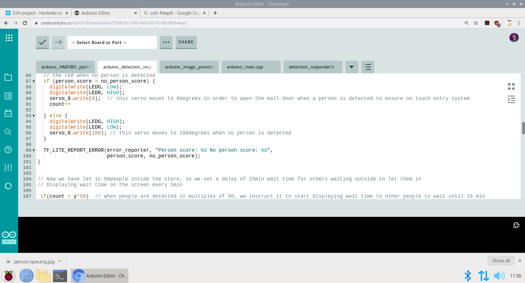
Setting up the ThingSpeak Dashboard:
Since the features in Thingspeak Dashboard are limited, I will not be implementing the Time prediction algorithm right now but I am working on the logic to communicate and write data from the Dashboard to microcontroller to perform the time calculation algorithm.
In the ThingSpeak Dashboard, I have added two fields; one for entry and the other one for exit.
The co-ordinates for the store or mall for which the queuing system is displayed, is also added in the form of a map.
The data displayed for the first field is gathered through the entry responding logic and the data displayed for the second field is gathered through the exit responding logic.
This is the snip of the two different logics used in the model.
The ThingSpeak Dashboard can be made available to the the staff of the store to check the number of people entering the store in real time and the number of people exiting the store in real time. This data can also be observed to see the analysis of the data at a given day at a a given time to check and impose further restrictions if required if the limit of people in the store exceeds the expected number of people at a given day
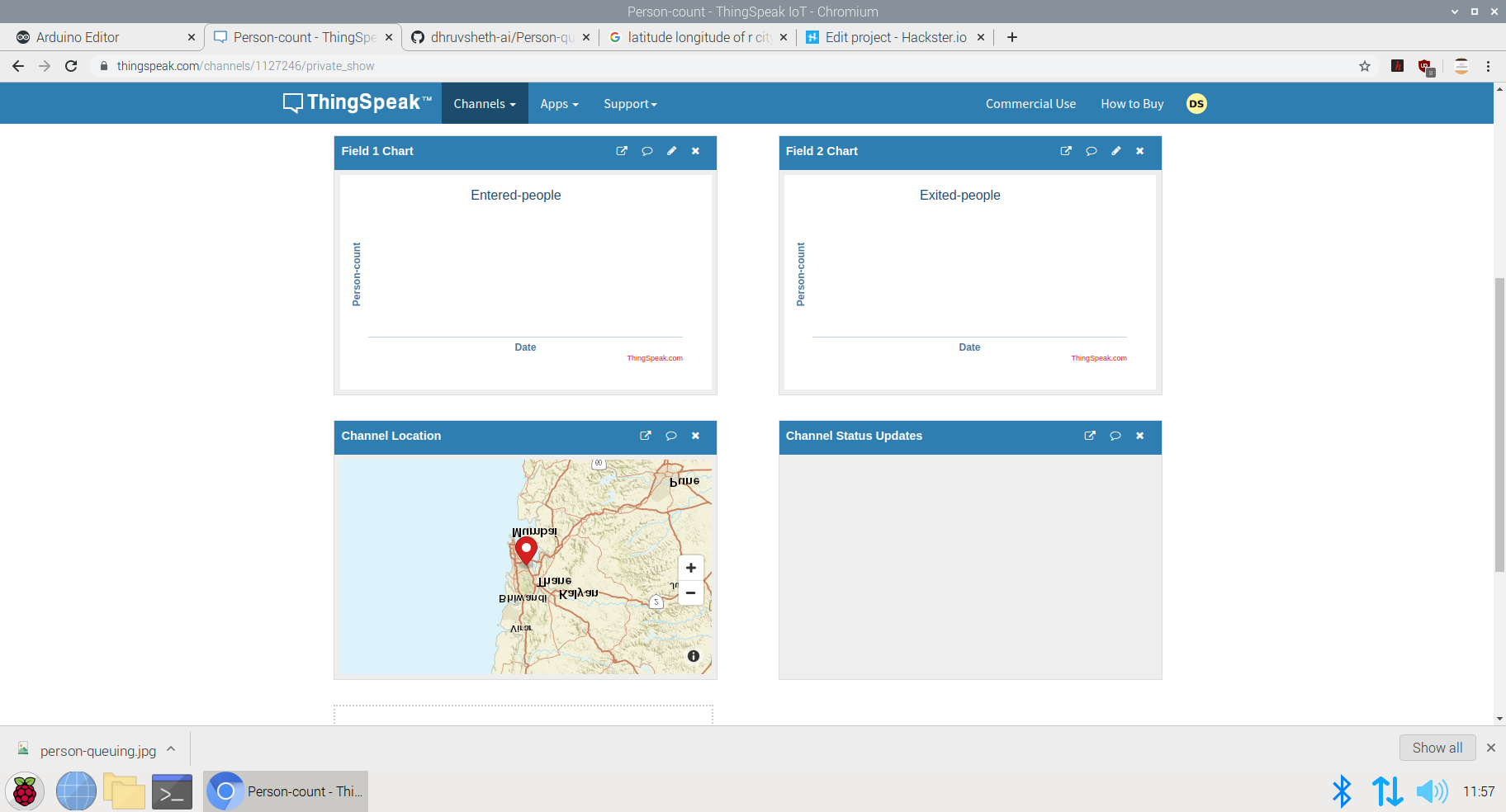
This Dashboard can be viewed here:IoT Dashboard
The following represents the field created for this purpose.
Now, a question might arise that for person detection model that this model can be replaced by ultrasonic or infrared sensors. Flaws in Ultrasonic Sensors or Infrared Based Sensors:These sensors are not exactly accurate and for the real time person count display, these sensors may provide wrong readings. Also, these sensors add as additional hardwares while in Go to Market Solutions, the person detection algorithm can be implemented in existing cameras and can reduce hardware cost. The data from these cameras could be sent to the Arduino BLE sense for central Classification and data processing.
GO TO MARKET &PRACTICALITY:
- Malls and Supermarkets can use this to identify The count of people entering and exiting the mall in real time.
- Implement Strategies using this data to ensure Safety and Compliance with efficient Queue management algorithms.
- Decrease Labour and automate Queue Management Process
- Offer Dashboard to the visitors to monitor the density of people inside the mall and accordingly visit the mall at the safest point of time.
- This product can be used to ensure the visitors that the mall is a safe place and hence, can increase the sales and visits following Government guidelines
- Companies offering Ai and IoT based solutions can invest for mass production and distribution.
- The more the supermarkets using this product, the more the access to data to the government and more the choice to customers to select the preferable safest place in their locality along with the the queue time required for each store can be monitored. This will lead to a wide range of options of supermarkets in the locality comparing the queue time and safety.
- Comparatively affordable solution as compared to manual queuing system and updating information manually to the Dashboard.
- Utilize real-time CCTV footage to impose Queue management in a mall/shop through person detection in terms of timely trends and spatial analysis of person density in the mall.
- Enable Stores to make better, data-driven decisions that ensure your safety and efficient Queues based on autonomous queuing system.
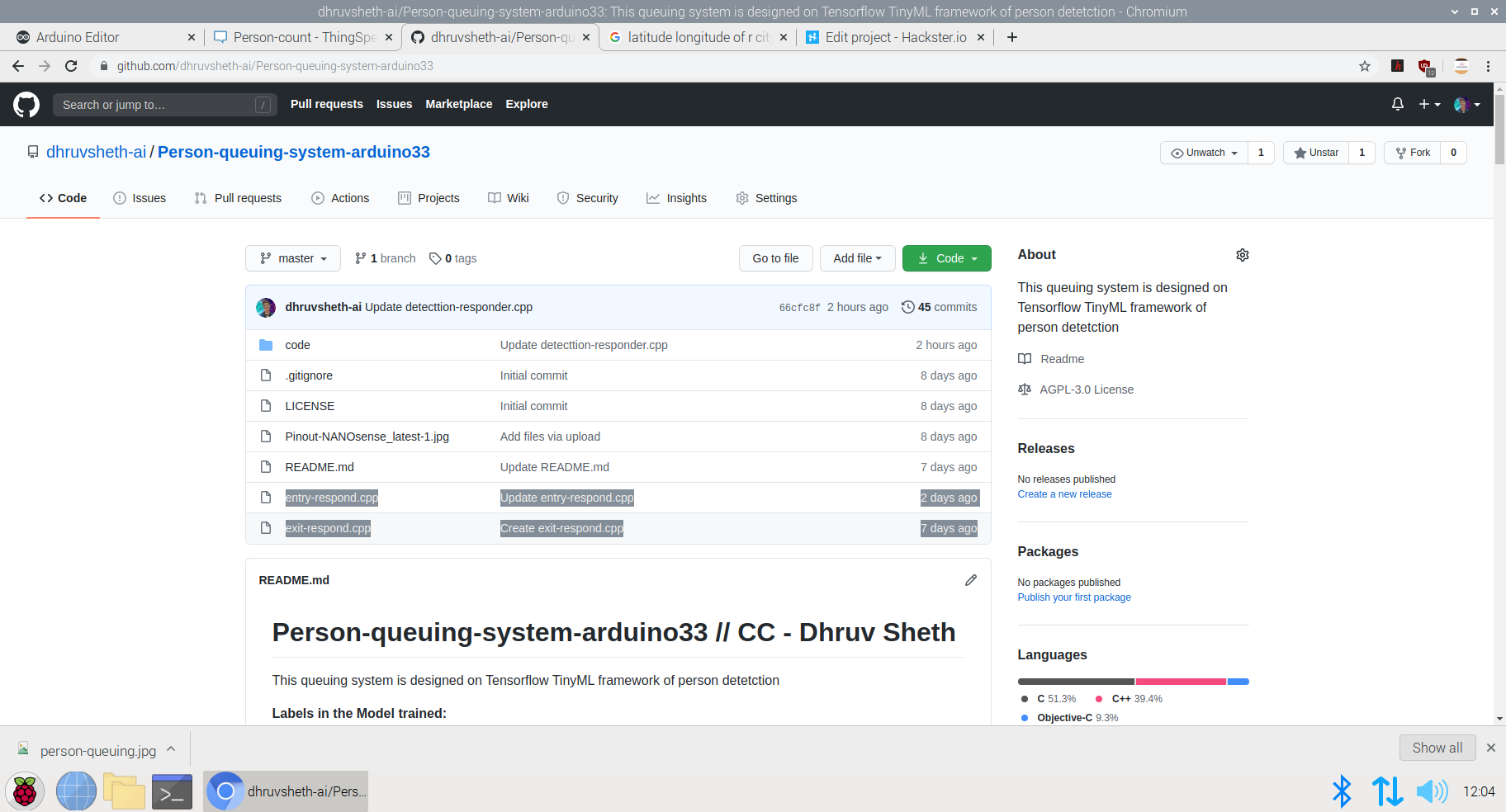
Github Code:Arduino Autonomous TinyML and IoT based queuing system.
Addition to the Existing Person Detection Algorithm- Mask Detection System:
Mask Detection Model based on TinyML :
Dr. Kierstin Kennedy, chief of hospital medicine at the University of Alabama at Birmingham, said, “Masks can protect against any infectious illness that may be spread by droplets. For example, the flu, pertussis (whooping cough), or pneumonia.”
Adding that wearing a cloth mask has benefits beyond slowing the spread of COVID-19, and that source control can reduce the transmission of many other easily spread respiratory infections — the kind that typically render people infectious even before they display symptoms, like influenza.
Until the threat of this pandemic has been neutralized, people should embrace the protection masks allow them to provide to those around them.
After all, it’s not necessarily about you — it’s about everyone you come in contact with.
It’s not at all uncommon to be an asymptomatic carrier of the new coronavirus — which means that even if you have no symptoms at all, you could potentially transmit the virus to someone who could then become gravely ill or even die.
Adhering to this, I decided to increase the necessity of wearing face-masks along with touch-free systems to increase safety in malls and supermarkets. Along with the person detection algorithm, I decided to make a custom face mask detection model which detects face masks and displays this data on the ThingSpeak IoT dashboard to increase awareness among mall staff as well as the visitors coming inside so that they are aware of the time trends when the most number of people are without masks. Through this there is a increases of sense of warning and awareness in people to wear masks. Accordingly, the store staff can keep a monitor on these trends and increase restrictions based on data driven statistics.
Deciding upon the Logic and Dataset of the Model:
This is an overall Logic used in most of face mask detection algorithms. Since, we are deploying this model to an Arduino 33 BLE Sense, the deployment process of this model will vary.
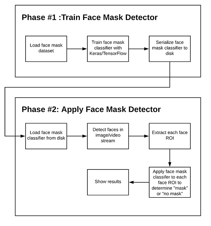
There are two steps involved in constructing the model for Face Mask Detection.
- Training: Here we’ll focus on loading our face mask detection dataset from disk, training a model (using Keras/TensorFlow) on this dataset, and then serializing the face mask detector to disk
- Deployment: Once the face mask detector is trained, we can then move on to loading the mask detector, performing face detection, and then classifying each face as
maskorno_mask
Dataset used in training this model:
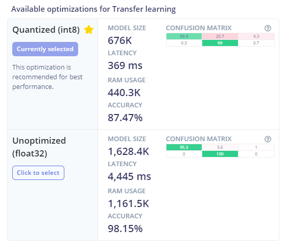
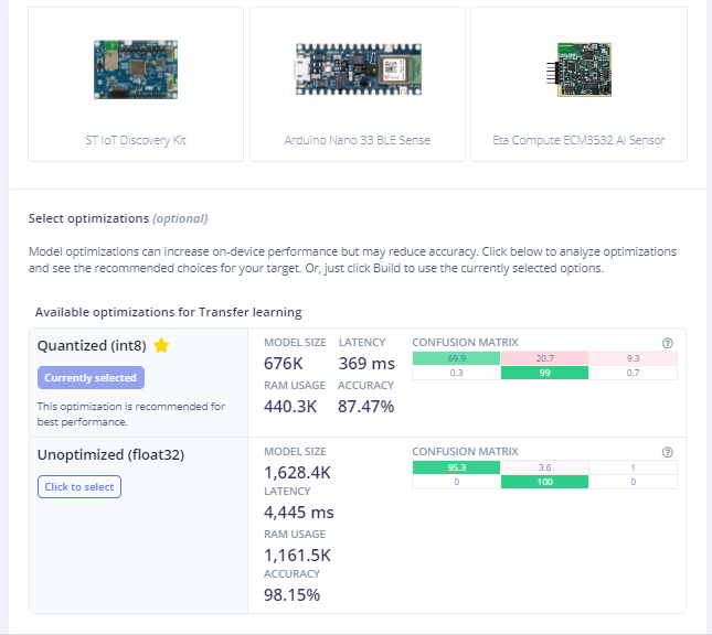
The dataset used in this process consists of 3500 images but to reduce the size of the model, and feed in accurate model images, I have used 813 images to increase accuracy of the model by decreasing bulk size. This model is an average 676K in size and utilizes nearly 440.3K Ram. Since this model is the optimized version of the original model, the accuracy of the model is 87.47% as compared to 98.15% in the non-optimized one.
The following Softwares have been used in designing this model:
- TensorFlow lite
- ThingSpeak
- Arduino Web Editor
Heading towards designing the model in EdgeImpulse Studio:
Powerful deep learning models (based on artificial neural networks) are now reaching microcontrollers. Over the past year great strides were made in making deep learning models smaller, faster and runnable on embedded hardware through projects like TensorFlow Lite for Microcontrollers, uTensor and Arm’s CMSIS-NN; but building a quality dataset, extracting the right features, training and deploying these models is can still be complicated.
Using Edge Impulse you can now quickly collect real-world sensor data, train ML models on this data in the cloud, and then deploy the model back to your Arduino device. From there you can integrate the model into your Arduino sketches with a single function call.
Step 1 - Acquisition of Data in the Edge Impulse Studio:
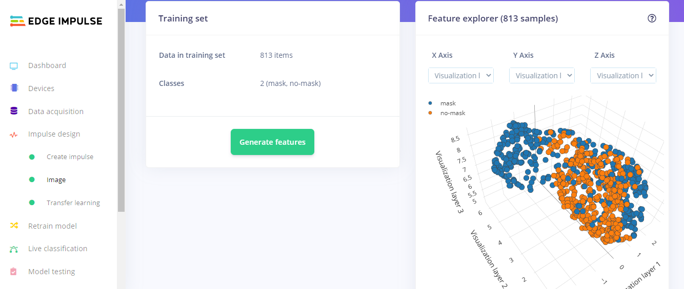
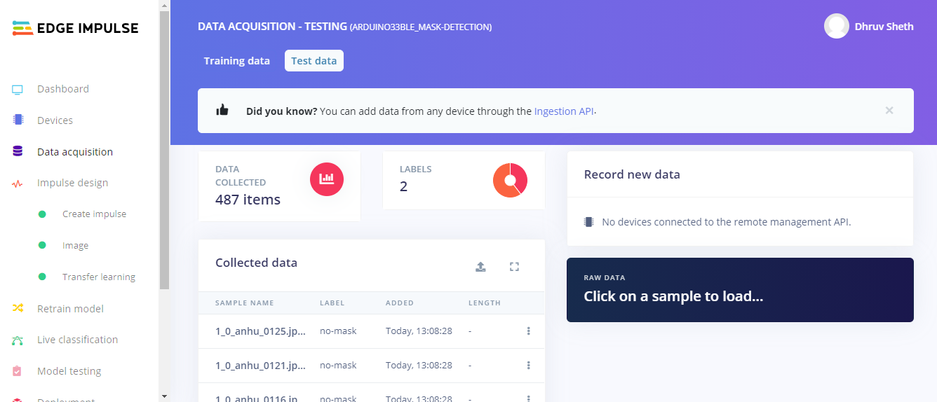
Using the dataset of 3500 images, I filtered these images to the best performing images and finally fed in 813 images totally in the Training Data and 487 images in the testing Data. I labelled these classes as mask and no_mask.
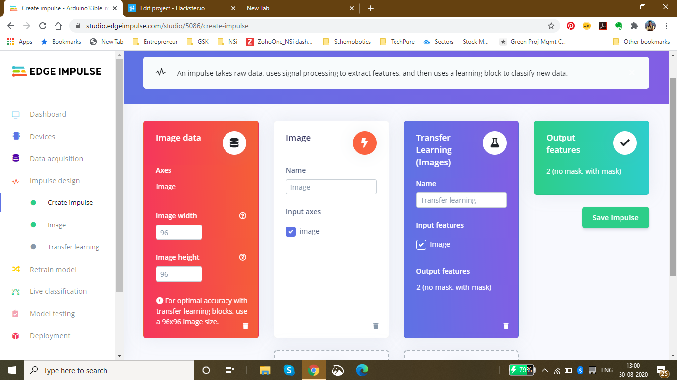
Then, I went ahead creating an impulse design which best suited the Model type. For optimal accuracy its recommended to use a standard image size which is 96*96 and also works the best on the Arduino 33 BLE Sense. Since the input type was images, I went ahead and selected "images" in the processing block. For the transfer learning block, the type recommended for image learning is Transfer Learning (Images) which is a Fine tune a pre-trained image model on your data. with Good performance even with relatively small image datasets.
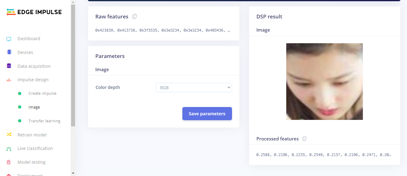
The next step was saving the parameters based on color depth. Here, I have selected RGB because in the dataset I am using for mask detection, color is also an important feature of classification instead of grayscale. In this page, we can also see the raw features with the processed features of the image
After Feature Generation I obtained the classification graph or the feature explorer where I could see the classes based on their classifications. The blue dots represent mask images and the orange dots represent the no_mask images.
In this feature generation, I obtained a fair classification with a distinct classification plot.
Finally, Moving on to the Transfer Learning Plot:
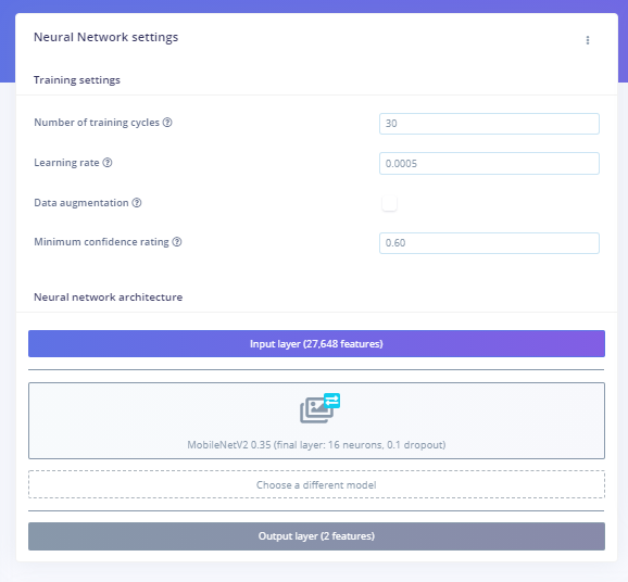
Here, I set the number of training cycles/epochs as 30 to get the highest accuracy with minimum val_loss. It so happens that if we train the model based on many training cycles, the accuracy graph starts to decrement after a certain number of epochs and the val_loss increases. Therefore I decided to limit the epochs to 30 which proved to be perfect. The learning rate is set to 0.0005 which is the default and proves to be the most appropriate. Here, I have used the MobileNetV2 0.35 (final layer:16 neurons, 0.1 dropout) model because this model is comparitively lightweight and accurate.
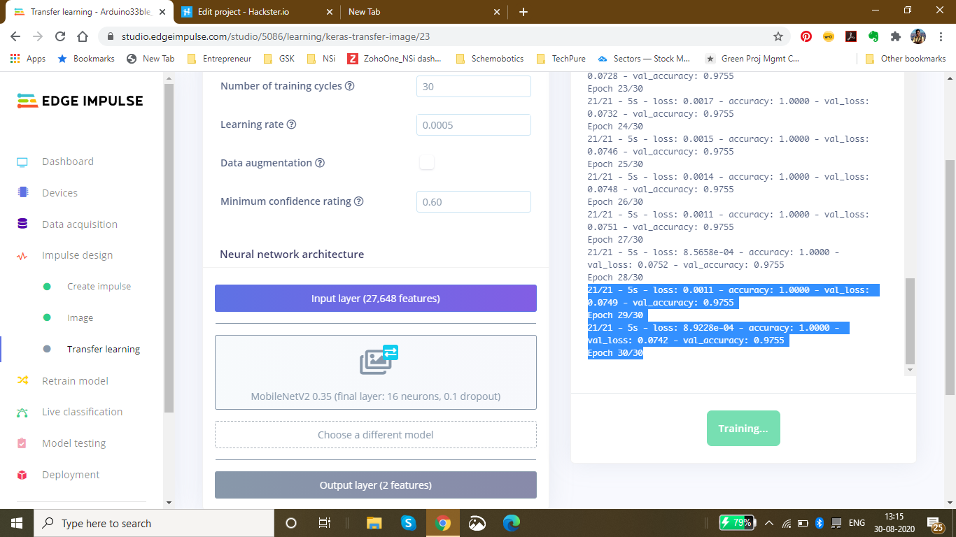
Finally after completing 30 epochs and 10 epochs of best model performance, I got the accuracy heading to 1.00 and the loss nearly 0 which was 0.0011. The following was the ouput during the training process:
Saving best performing model... Converting TensorFlow Lite float32 model... Converting TensorFlow Lite int8 quantized model with float32 input and output...
- Epoch 9/10 21/21 - 5s - loss:0.0011 - accuracy:1.0000 - val_loss:0.0727 - val_accuracy:0.9755
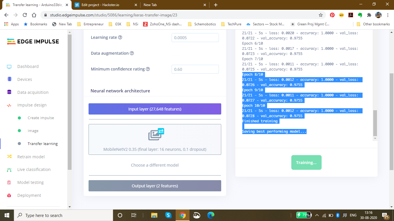
- Epoch 10/10 21/21 - 5s - loss:0.0012 - accuracy:1.0000 - val_loss:0.0728 - val_accuracy:0.9755 Finished training
This was the final output which I received after the training:
The accuracy to be 92.6% and the loss to be 0.19.
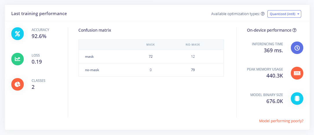
Finally Using the test data, I tested the accuracy and found it to be 98.15%.
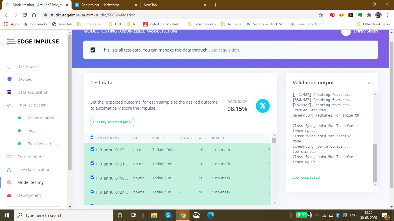
Finally since I had the model ready, I deployed it as an Arduino Library with the firmware to be the Arduino 33 BLE Sense:I got the zip folder of the library ready and started to make changes as per our requirements.
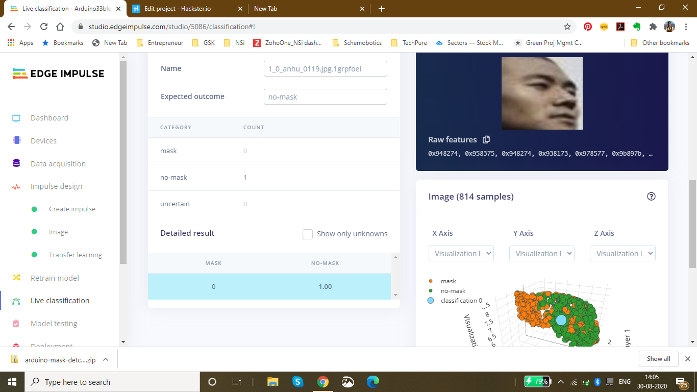
For a last confirmation, I live classified the data to ensure that the data is classified properly. I got the perfect results as expected:
Changing the code as per the output required in the model:
Here is a snippet of the main.ino code of the mask_detection model
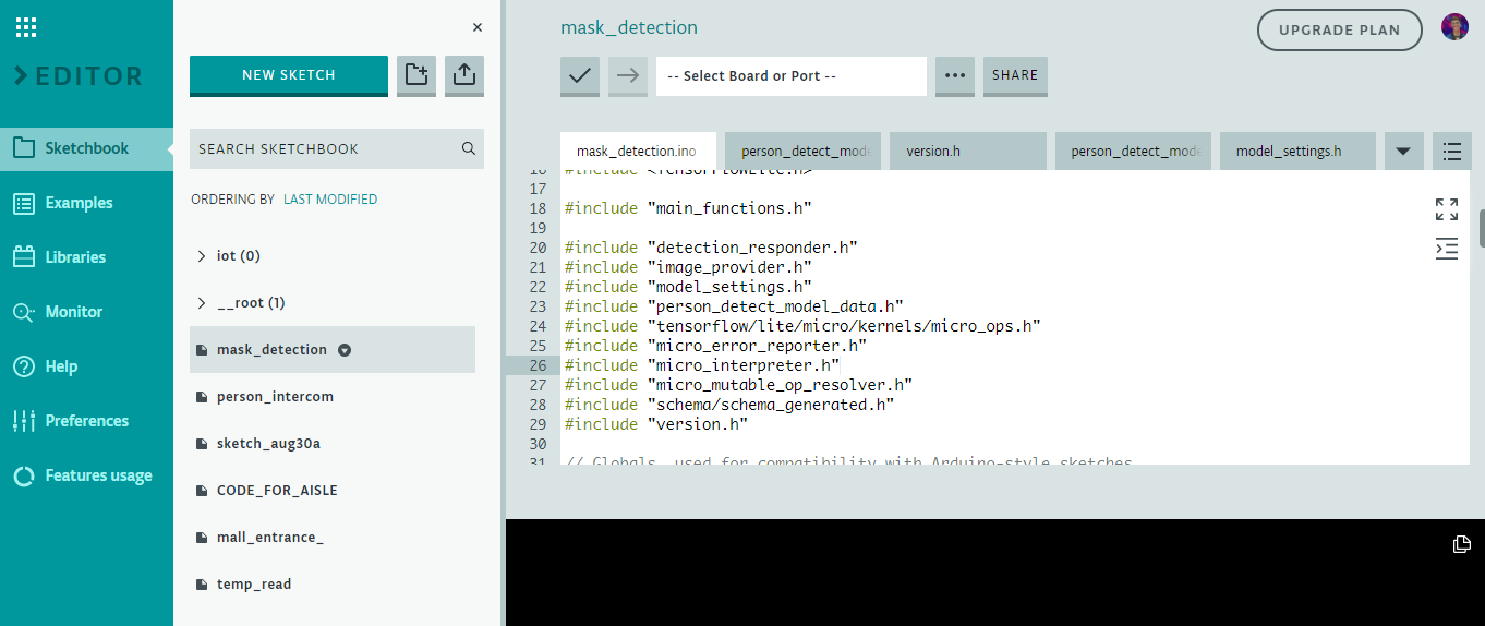
I have defined the arduino libraries required for the functioning of the model and based on the Tensorflow lite framework, I have designed this model.
This is the loop of some of the main functions in the model which are defined in the libraries. The main.ino code centralises these functions and accordingly loops them with a central code.
void loop() {
 // Get image from provider.
 if (kTfLiteOk !=GetImage(error_reporter, kNumCols, kNumRows, kNumChannels,
 input->data.uint8)) {
 TF_LITE_REPORT_ERROR(error_reporter, "Image capture failed.");
 }

 // Run the model on this input and make sure it succeeds.
 if (kTfLiteOk !=interpreter->Invoke()) {
 TF_LITE_REPORT_ERROR(error_reporter, "Invoke failed.");
 }

 TfLiteTensor* output =interpreter->output(0);

 // Process the inference results.
 uint8_t mask_score =output->data.uint8[kmaskIndex];
 uint8_t no_mask_score =output->data.uint8[kno-maskIndex];
 RespondToDetection(error_reporter, mask_score, no_mask_score);
}
The processed data of this model can be viewed here :(This file is relatively large and varies as per the dataset size of the model) Arduino_mask_detect_model_data.h
For providing image, I will be using the Arducam mini 2mp plus for visual data input. A snippet from the image_provider.h file is :
#include "image_provider.h"

/*
 * The sample requires the following third-party libraries to be installed and
 * configured:
 *
 * Arducam
 * -------
 * 1. Download https://github.com/ArduCAM/Arduino and copy its `ArduCAM`
 * subdirectory into `Arduino/libraries`. Commit #e216049 has been tested
 * with this code.
 * 2. Edit `Arduino/libraries/ArduCAM/memorysaver.h` and ensure that
 * "#define OV2640_MINI_2MP_PLUS" is not commented out. Ensure all other
 * defines in the same section are commented out.
 *
 * JPEGDecoder
 * -----------
 * 1. Install "JPEGDecoder" 1.8.0 from the Arduino library manager.
 * 2. Edit "Arduino/Libraries/JPEGDecoder/src/User_Config.h" and comment out
 * "#define LOAD_SD_LIBRARY" and "#define LOAD_SDFAT_LIBRARY".
 */

#if defined(ARDUINO) &&!defined(ARDUINO_ARDUINO_NANO33BLE)
#define ARDUINO_EXCLUDE_CODE
#endif // defined(ARDUINO) &&!defined(ARDUINO_ARDUINO_NANO33BLE)

#ifndef ARDUINO_EXCLUDE_CODE

// Required by Arducam library
#include
#include
#include
// Arducam library
#include
// JPEGDecoder library
#include

// Checks that the Arducam library has been correctly configured
#if !(defined OV2640_MINI_2MP_PLUS)
#error Please select the hardware platform and camera module in the Arduino/libraries/ArduCAM/memorysaver.h
#endif
The Arduino_detection_responder.cpp code performs the inference and delivers the main output required for the code. Here, when a person with a mask is detected, we are opening the gate and if a person with no mask is detected, we are closing the gate.
// Switch on the green LED when a mask is detected,
 // the red when no mask is detected
 if (mask_score> no_mask_score) {
 digitalWrite(LEDG, LOW);
 digitalWrite(LEDR, HIGH);
 servo_8.write(0); // this servo moves to 0degrees in order to open the mall door when a person is detected to ensure no touch entry system
 count++
 } else {
 digitalWrite(LEDG, HIGH);
 digitalWrite(LEDR, LOW);
 servo_8.write(180); // this servo moves to 180degrees when no person is detected
 count2++
 }
The count and count2 are variable integers and increment everytime a mask is detected, or not detected. These counts are then displayed onto the ThingSpeak IoT Dashboard as follows:
The graph displays the mask and no mask count over time. This thingspeak dashboard is setup in the Arduino code as seen here:
#include
#include
WiFiMulti WiFiMulti;
const char* ssid ="Yourssid"; // Your SSID (Name of your WiFi)
const char* password ="Wifipass"; //Your Wifi password
const char* host ="api.thingspeak.com/channels/1118220";
String api_key ="9BRPKINQJJT2WMWP"; // Your API Key provied by thingspeak
The complete code for responder can be viewed here:Arduino_detection_responder.cpp
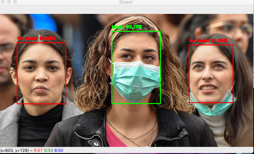
Github Code can be viewed here:Arduino Mask Detetction
The ThingSpeak dashboard can be viewed here - IoT Dashboard
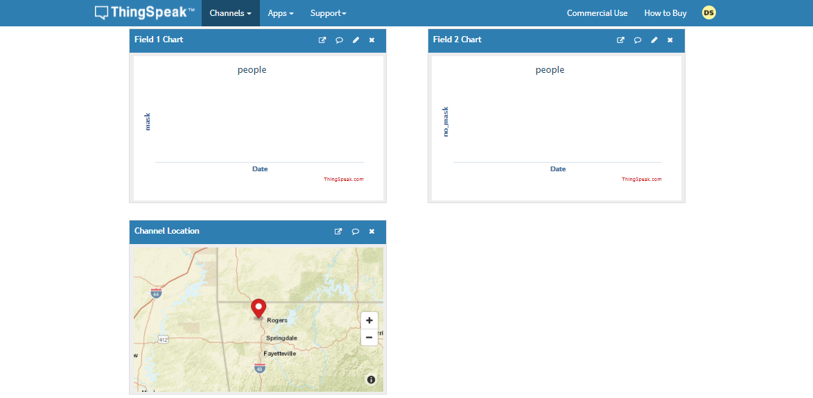
5th project - Person detection in supermarket Aisles and self-sanitisation system:
Just as malls and supermarkets and retail sectors have opened, a risk of contamination of the virus has increased. The main risk that is faced is in supermarkets and stores. The stores could be related to clothes, food and even electronics, the virus could deposit and stay on these surfaces for a long time.
Early data suggests the new coronavirus can live on surfaces for several days
The new coronavirus is, well, new — and there's still much to learn about how easily the virus can spread via contaminated surfaces. But early evidence indicates that the surface survivability of the new coronavirus is similar to that of SARS, a related coronavirus first identified in 2002. Depending on the surface, the virus can live on surfaces for a few hours or up to several days.
The new coronavirus seems to be able to survive the longest on plastic and stainless steel — potentially as long as three days on these surfaces. It can also live on cardboard for up to 24 hours.
Find out what this means for the things you touch throughout the day, including your:
- Clothes
- Food
- Groceries
- Packages
- Elektronica
The coronavirus pandemic has breathed new life into a decades-old technique that can zap viruses and bacteria:ultraviolet light.
Hospitals have been using it for years to cut down on the spread of drug-resistant superbugs and to disinfect surgical suites. But there is now interest in using the technology in spaces like schools, office buildings, and restaurants to help reduce coronavirus transmission once public spaces are open again.
The sanitizing effects of UV lights have been seen with other coronaviruses, including the one that causes severe acute respiratory syndrome (SARS). Studies have shown that it can be used against other coronaviruses. One study found at least 15 minutes of UVC exposure inactivated SARS, making it impossible for the virus to replicate. New York's Metropolitan Transit Authority announced the use of UV light on subway cars, buses, technology centers, and offices. The National Academy of Sciences says although there is no concrete evidence for UV’s effectiveness on the virus that causes COVID-19, it has worked on other similar viruses, so it would likely fight this one too.
Abiding by the given information, Malls and Supermarkets have started imposing solutions based on UV sanitisation on manual basis. This consumes a lot of time and also, the data is unavailable. In manual process, one does not know which area has been exposed to human touch more or which are has the highest risk of contamination.
To automate this process and to provide real time spatial analysis of the data collected and the rate of contamination in an area.

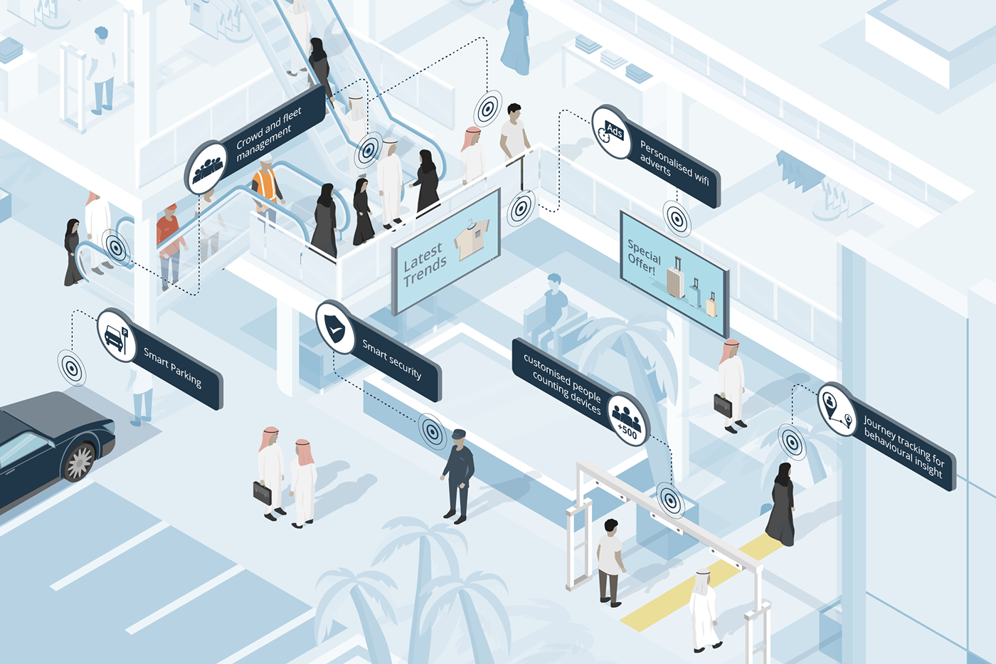
The above images demonstrate the distribution of population across the mall. As it is clearly seen in Figure B, the density near the escalator is comparatively high as compared to the density on the second floor. Manually keeping a track of this continuously changing data in real time and accordingly, sanitising the areas/aisles according to the rate of contamination is not a manual task.
Hence, I decided to make a robust solution for automating this process with the help of TinyML computer Vision &IoT deployed on the Arduino 33 BLE Sense.
The structured framework of this system is as follows:
These models are individually deployed on the Aisles and Areas of the malls and supermarkets close to the Area which has to be sanitised. Since the model utilises person detection Algorithm, the placement of the model is done accordingly.
In this model, for accumulation of Video data, the Arducam mini 2MP Plus is used. The Arducam Mini 2MP Plus continuously gathers visual data and sends this data to the Arduino Nano 33 BLE Sense for processing and classification. The Arduino classifies the data and accordingly processes commands. If a person is detected, the count of people increments by 1 on detection of each person near the Aisle.
A certain threshold for the count of people is set depending upon the rate of contamination based on the object type in that area. The rate of contamination and threshold for food aisle, clothes aisle, sports aisle and Electronic aisle is different.
Accordingly taking into consideration an average threshold, if 25 people are detected, the area is safe. If the count increases to 50, the area is heading towards contamination and the visitors are given an alert. If the count increases to 100, the area is declared contaminated and the people are warned to be careful while touching objects. Finally if the threshold limit is crosses which is 150, the area is autonomously sanitised using UV Light.
The alerts generated are based on LED Colours. Green is an indication for safe, blue is an indication for alert, and Red is an indication for Warning!. These LED based alerts are installed in the respective areas individually.
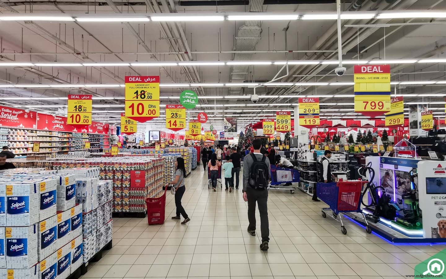
The above image shows the various aisles in the malls where the system can be installed.
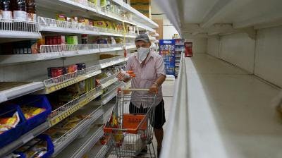
The above image shows the area of installation of Arducam or similar visual data capturing device to cover a wide spectrum of people walking through the aisle.
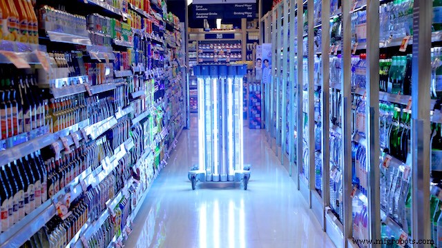

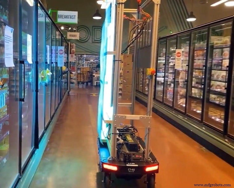
The above Images show a demo implementation of the UV Sanitisation Lights in suitable areas of the aisles. This UV light covers a large spectrum of area that can be sanitised together.
Implementation of the autonomous sanitisation system.
The following Softwares have been used in designing this model:
- TensorFlow lite
- ThingSpeak
- Arduino Web Editor
In this person detection model, I have used the Pre-trained TensorFlow Person detection model apt for the project. This pre-trained model consists of three classes out of which the third class is with undefined set of data:
"unused",
"person",
"notperson"
In our model we have the Arducam Mini 2mp plus to carry out image intake and this image data with a decent rate of fps is sent to the Arduino Nano 33 BLE Sense for processing and and classification. Since the Microcontroller is capable of providing 256kb RAM, we change the image size of each image to a standard 96*96 for processing and classification. The Arduino Tensorflow Lite network consists of a deep learning framework as:
- Depthwise Conv_2D
- Conv_2D
- AVERAGE Pool_2D
- Flatten layer
This deep learning framework is used to train the Person detection model.
The following is the most important function defined while processing outputs on the Microcontroller via Arduino_detetction_responder.cpp
// Process the inference results.
 uint8_t person_score =output->data.uint8[kPersonIndex];
 uint8_t no_person_score =output->data.uint8[kNotAPersonIndex];
 RespondToDetection(error_reporter, person_score, no_person_score);
In the following function defining, the person_score , the no_person_score have been defined on the rate of classification of the data.
using these defined functions, I will be using it to give certain outputs on the basis of confidence of the person_score and the no_person_score .
The detection responder logic of the code works in the following way:
├── Person Detection and sanitisation
├── Arducam mini 2MP Plus
│ ├──Image and Video Data to Arduino
├── Arduino BLE 33 Sense
│ ├── processing and classification of the input data
│ │ ├── If person detected, increment the count by 1
│ │ ├── If no person detected, do nothing
│ │ ├── Send the number of people entered count to to ThingSpeak Dashboard via ESP8266 -01
│ │ | ├── If people count is uptil 25
│ │ │ | ├── Indicate the area to be safe by flashing green light
│ │ | ├── If people count is uptil 50
│ │ │ | ├── Indicate the people to be aware by flashing blue light
│ │ | ├── If people count is uptil 100
│ │ │ | ├── Indicate the area to be contaminated by flashing Red light
│ │ | ├── If people count is between 150 to 175
│ │ │ | ├── Sanitise the area by activating the UV light
│ │ │ | ├── Reset the person count to 0 since the area has been sanitised
│ │ └── ...Repeat the loop
According to the logic used in the model, the Arducam Mini 2MP Plus will continuously capture visual data and send this data to the Arduino Nano 33 BLE sense to process and classify. This model size is 125Kb. Once the image is processed, the Arduino starts to classify the data captured. If a person is detected in the model, the person count increases by 1. This person count is continuously sent to the ThingSpeak dashboard via ESP8266- 01 IoT module. The person count enables the supermarket staff with the data of number of visitors in a particular area at any given point of time. The staff can generate data driven decisions to take action in an area if the visitor count is significantly high.
Proceeding to the output, if the person count is between 1 to 25, the Area is declared safe by flashing the green LED. If the person count is between 26 to 50, the visitors are given an alert by flashing BLUE LED. If the count is between 51 to 100, the area is declared contaminated by flashing the RED LED. When the count surpasses a certain threshold, here taken to be 150, the UV light is turned on until the 165th person passes the area. In this way the Area is sanitised. Similarly the count of people is reset to 0 since the area has been sanitised.
Working of the Firmware:

This model comprises of the following firmware used:
- Arduino 33 BLE sense - Used to process the data gathered, classifies the data processes, sends the command according to the logic fed.
- Arducam Mini 2mp plus - Continuous Raw data image accumulation from source.
- Adafruit lithium ion charger - Used to deliver charge through the lithium battery
- Lithium ion Battery - power source
- ESP8266 - 01 - Used for sending data to the ThingSpeak dashboard via WiFi network.
- RGB LED - Used for flashing Signals based on the status of contamination
- UV Light - Used to Sanitise the Area ( Since this is a prototype, an LED is displayed. In the actual solution, the UV light consumes a lot of energy hence an external power source needs to be provided. )
Functioning and Working of Logic in Code:
The following are the Libraries included in themain.ino c ode for functioning of the model.
#include

#include "main_functions.h"

#include "detection_responder.h"
#include "image_provider.h"
#include "model_settings.h"
#include "person_detect_model_data.h"
#include "tensorflow/lite/micro/kernels/micro_ops.h"
#include "tensorflow/lite/micro/micro_error_reporter.h"
#include "tensorflow/lite/micro/micro_interpreter.h"
#include "tensorflow/lite/micro/micro_mutable_op_resolver.h"
#include "tensorflow/lite/schema/schema_generated.h"
#include "tensorflow/lite/version.h"
The main outcome of the model is dependent on the logic fed in detection_responder.cpp. This snippet shows the generalized threshold of the contamination of the object set to a count of 101.
void RespondToDetection(tflite::ErrorReporter* error_reporter,
 uint8_t person_score, uint8_t no_person_score) {
 static bool is_initialized =false;
 if (!is_initialized) {
 // Pins for the built-in RGB LEDs on the Arduino Nano 33 BLE Sense
 pinMode(LEDR, OUTPUT);
 pinMode(LEDG, OUTPUT);
 pinMode(LEDB, OUTPUT);
 is_initialized =true;
 }

 // Note:The RGB LEDs on the Arduino Nano 33 BLE
 // Sense are on when the pin is LOW, off when HIGH.

 // Switch the person/not person LEDs off
 digitalWrite(LEDG, HIGH);
 digitalWrite(LEDR, HIGH);

 // Flash the blue LED after every inference.
 digitalWrite(LEDB, LOW);
 delay(100);
 digitalWrite(LEDB, HIGH);

 // Switch on the green LED when a person is detected,
 // the red when no person is detected
 if (person_score> no_person_score) {
 digitalWrite(LEDG, LOW);
 digitalWrite(LEDR, HIGH);
 count++
 } else {
 digitalWrite(LEDG, HIGH);
 digitalWrite(LEDR, LOW);
 }

 TF_LITE_REPORT_ERROR(error_reporter, "Person score:%d No person score:%d",
 person_score, no_person_score);
}


 if (constrain(count, 1, 50)) {
 digitalWrite(LEDGREEN, LOW); // This is a green LED which means area is not contaminated yet
}
 if (constrain(count, 51, 75)) {
 digitalWrite(LEDBLUE, LOW); // This is a b led so that people are alert that more than 50 people
}
 if (constrain(count, 76,100)) {
 digitalWrite(LEDRED, LOW); // This is a red LED which warns people that this area is contaminated and one should take care while touching objects
}
 if (constrain(count, 101, 110)) {
 digitalWrite(UV, LOW); // This is an Ultraviolet Light which ensures that after 100 people have touched the aisle objects, it sanitises the area with UV light
 }
 if (count> 111) {
 (count =0); // this resets the person count to 0 once the area has been sanitised by UV light
 }
 } // In this way, a simple math function has been written by me on the arduino nano 33 ble sense which alerts people and sanitizes areas
/* cc - Dhruv Sheth */
The below snippet is carried out by the ESP8266 -01 module to send data to the allocated field in the ThingSpeak Dashboard:
void Send_Data()
{


 // Use WiFiClient class to create TCP connections
 WiFiClient client;

 const int httpPort =80;

 if (!client.connect(host, httpPort)) {
 Serial.println("connection failed");
 return;
 }
 else
 {
 String data_to_send =api_key;
 data_to_send +="&field1=";
 data_to_send +=String(count);
 data_to_send +="\r\n\";

 client.print("POST /update HTTP/1.1\n");
 client.print("Host:api.thingspeak.com\n");
 client.print("Connection:close\n");
 client.print("X-THINGSPEAKAPIKEY:" + api_key + "\n");
 client.print("Content-Type:application/x-www-form-urlencoded\n");
 client.print("Content-Length:");
 client.print(data_to_send.length());
 client.print("\n\n");
 client.print(data_to_send);

 delay(10); // reduced delay to perform real time data collection
 }

 client.stop();

} 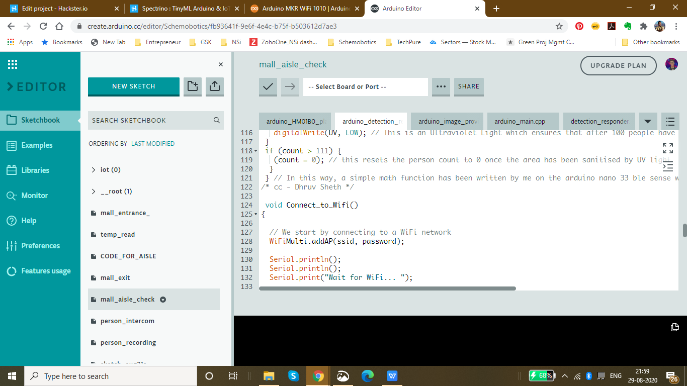
The threshold for each Aisle inside the mall is set to be different according to the rate of contamination of the model. This data can be altered according to the need of the malls or supermarkets. These thresholds can also be altered according to the time trends and the population density in that area.
Threshold set for the Clothes Aisle:
if (constrain(count, 1, 50)) {
 digitalWrite(LEDGREEN, LOW); // This is a green LED which means area is not contaminated yet
}
 if (constrain(count, 51, 75)) {
 digitalWrite(LEDBLUE, LOW); // This is a b led so that people are alert that more than 50 people
}
 if (constrain(count, 76,100)) {
 digitalWrite(LEDRED, LOW); // This is a red LED which warns people that this area is contaminated and one should take care while touching objects
}
 if (constrain(count, 101, 110)) {
 digitalWrite(UV, LOW); // This is an Ultraviolet Light which ensures that after 100 people have touched the aisle objects, it sanitises the area with UV light
 }
 if (count> 111) {
 (count =0); // this resets the person count to 0 once the area has been sanitised by UV light
 }
Threshold for the Electronics Aisle, since the virus stays on these surfaces comparatively less, we have set a higher threshold in this case.
if (constrain(count, 1, 75)) {
 digitalWrite(LEDGREEN, LOW); // This is a green LED which means area is not contaminated yet
}
 if (constrain(count, 76, 180)) {
 digitalWrite(LEDBLUE, LOW); // This is a b led so that people are alert that more than 50 people
}
 if (constrain(count, 181,225)) {
 digitalWrite(LEDRED, LOW); // This is a red LED which warns people that this area is contaminated and one should take care while touching objects
}
 if (constrain(count, 225, 240)) {
 digitalWrite(UV, LOW); // This is an Ultraviolet Light which ensures that after 100 people have touched the aisle objects, it sanitises the area with UV light
 }
 if (count> 111) {
 (count =0); // this resets the person count to 0 once the area has been sanitised by UV light
 }
Threshold set for Food and eatables:, Since these are consumptives, they face a higher risk of contamination. Hence, a lower threshold is set in this case.
if (constrain(count, 1, 25)) {
 digitalWrite(LEDGREEN, LOW); // This is a green LED which means area is not contaminated yet
}
 if (constrain(count, 25, 50)) {
 digitalWrite(LEDBLUE, LOW); // This is a b led so that people are alert that more than 50 people
}
 if (constrain(count, 51,75)) {
 digitalWrite(LEDRED, LOW); // This is a red LED which warns people that this area is contaminated and one should take care while touching objects
}
 if (constrain(count, 76, 90)) {
 digitalWrite(UV, LOW); // This is an Ultraviolet Light which ensures that after 100 people have touched the aisle objects, it sanitises the area with UV light
 }
 if (count> 91) {
 (count =0); // this resets the person count to 0 once the area has been sanitised by UV light
 }
Setting up the Thingspeak IoT Dashboard:
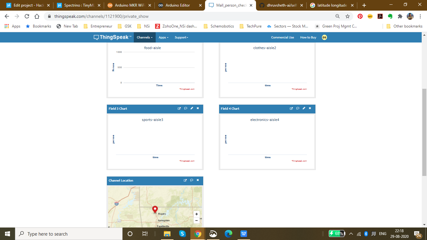
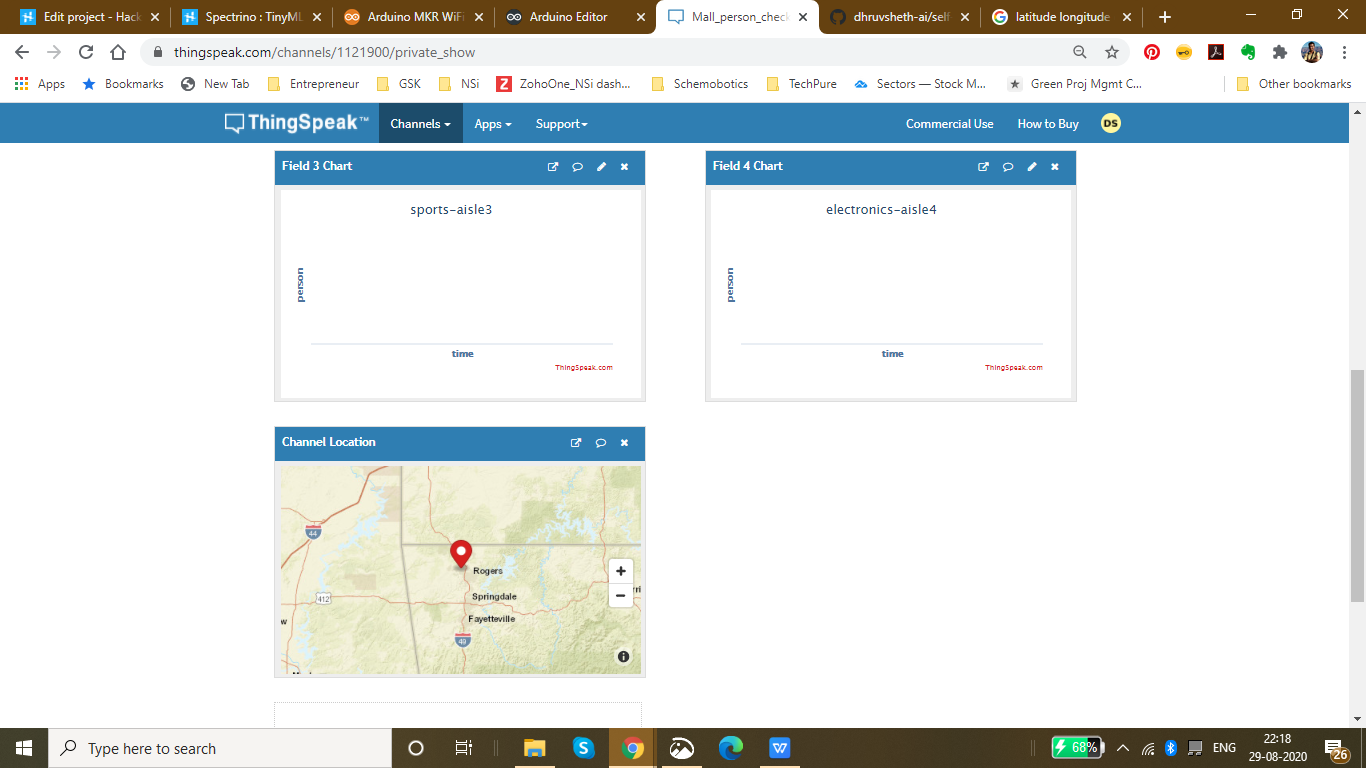
On the thingspeak dashboard, there are 4 fields which have been added for the 4 aisles that have been set up namely:
- Food-aisle
- Sports-aisle
- Clothes-aisle
- Electronics-aisle
The co-ordinate locations of the mall can be seen in the channel visualization which can be cumulatively displayed on a single dashboard through which the data for each supermarket and mall in a locality can be accessed.
The IoT Dashboard can be viewed here:IoT Dashboard
The fields and channels of aisles can be all displayed together on a single Thingspeak IoT Dashboard.
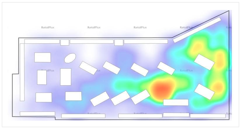
The above image shows a density plot of the density population in a given region in the store of a mall.
Currently I have been using the ThingSpeak Dashboard to plot the data in a graphical format. But, using the same data and Tableau visualizations, it is possible to plot the given data on the floor plot map of the Supermarket.
This data will be easily accessible to other visitors entering the supermarket and will be able to interpret data driven decisions like visiting the store which has a low population density.
Now a question might arise that what makes the product unique:
Currently, the UV sanitisation system is implemented on manual basis and hence the sanitisation system is carried out manually monitoring these areas. Autonomous UV robots are deployed in malls to gather plot data of mall and map these areas, hence autonomously sanitising these areas. These solutions are not capable of sanitising each aisle and area in the mall along with the flowing population of the people in the mall. The sanitisation is only limited to sanitising the lower part of these aisles and hence the upper parts are left unsanitised. These solutions are also comparatively expensive and they are not capable of continuous data monitoring and sanitisation respective to the rate of contamination. This means that they are unable to monitor the number of people who have passes through a certain area or aisle and hence are unable to sanitise areas according to their contamination.
Go to Market and Viability:
- Malls and Supermarkets can use this to identify The count of people in and density of people in a certain area in a store and impose self sanitisation process within the malls.
- Implement Strategies using this data to ensure Safety and Compliance with efficient Population Density monitoring algorithms.
- Decrease Labour and automate Sanitisation process.
- Offer Dashboard to the visitors to monitor the density of people at a certain area inside the mall and accordingly the visitors can have a view of the store with lowest density population and make decisions based on this data. The visitors can also have a view of the timely trends of sanitisation by viewing the abrupt change of person density graph in an area when sanitisation is conducted. ( Since, each time sanitisation in an area takes place, the person count is reset to 0 because the place is sanitised)
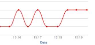
- This product can be used to ensure the visitors that the mall is a safe place and hence, can increase the sales and visits following Government guidelines
- Companies offering Ai and IoT based solutions can invest for mass production and distribution.
- The more the supermarkets using this product, the more the access to data to the government and more the choice to customers to select the preferable safest place in their locality and which store is continuously sanitised to be up to mark in terms of safety. This will lead to a wide range of options of supermarkets in the locality comparing the queue time and safety.
- Comparatively affordable solution as compared to autonomous UV Robot system and highly scalable in terms of data and services with IoT Dashboard provided.
- Utilize real-time CCTV footage to impose autonomous sanitisation system through person detection in terms of timely trends and spatial analysis of person density in the mall.
- Enable Stores to make better, data-driven decisions that ensure your safety and efficient Queues based on autonomous queuing system.
Github Link :https://github.com/dhruvsheth-ai/self-sanitisation-person-detection
PROJECT VIDEO:
Thank you for viewing my project!
Code
- Elevator Automation using "up" - "down" speech command
Elevator Automation using "up" - "down" speech commandArduino
The below is a .zip file of the Arduino LibraryNo preview (download only).
Mall Aisle Self Sanitization with Person Detection System
https://github.com/dhruvsheth-ai/self-sanitisation-person-detetctionTemperature monitoring system based on IoT
https://github.com/dhruvsheth-ai/temperature-arduino-iotMask Detection Algorithm
https://github.com/dhruvsheth-ai/ble-mask-detection-optimisedAutonomous Person Intercom based on TinyML
https://github.com/dhruvsheth-ai/person-autonomous-intercomElevator Automation using TinyML
https://github.com/dhruvsheth-ai/elevator-Automation-ARDUINOMall Entrance Person Detection and Queuing System
Queuing System based on TinyML person detection on Mall Entrance and exit connected via IoT Thingspeak dashboard for Live data monitoringhttps://github.com/dhruvsheth-ai/Person-queuing-system-arduino33Schema's
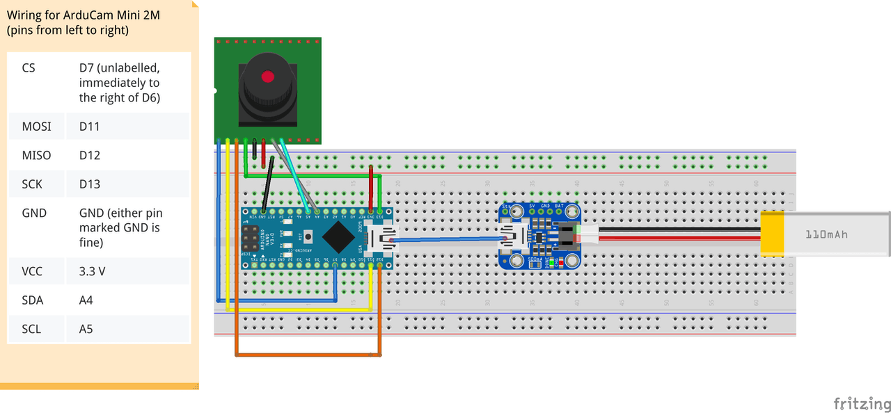
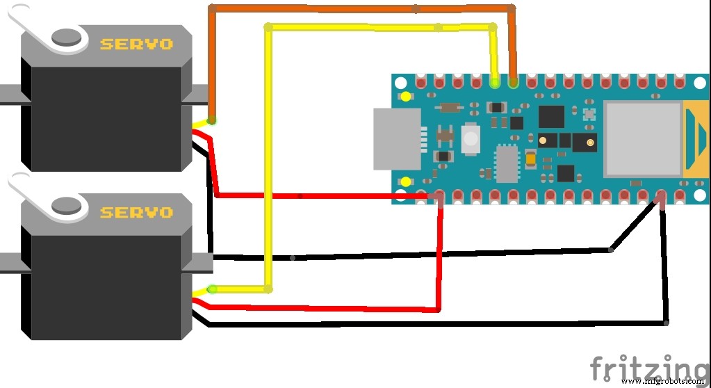
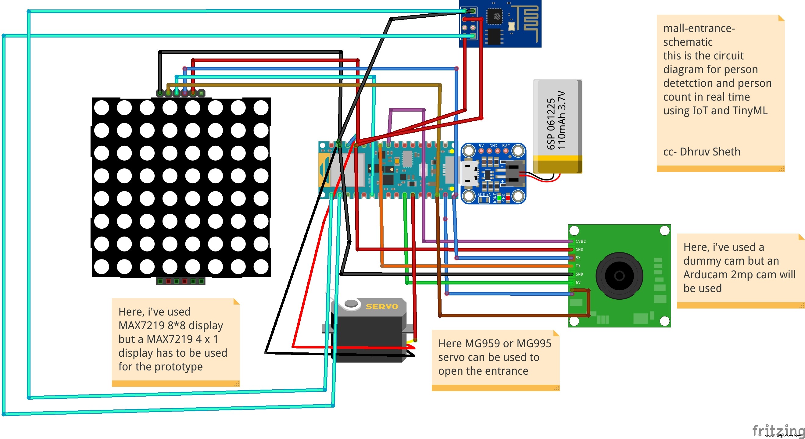 This is the Schematic for the Mall Aisle Person detection and self sanitization system that transfers data to ThingSpeak IoT Dashboard
 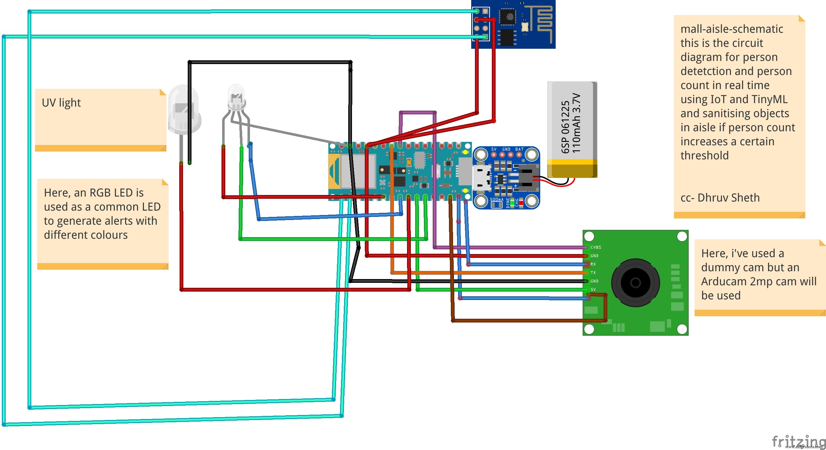 Detects a person present at the door and rings the bell and displays "person" on the LED Matrix as an alternative
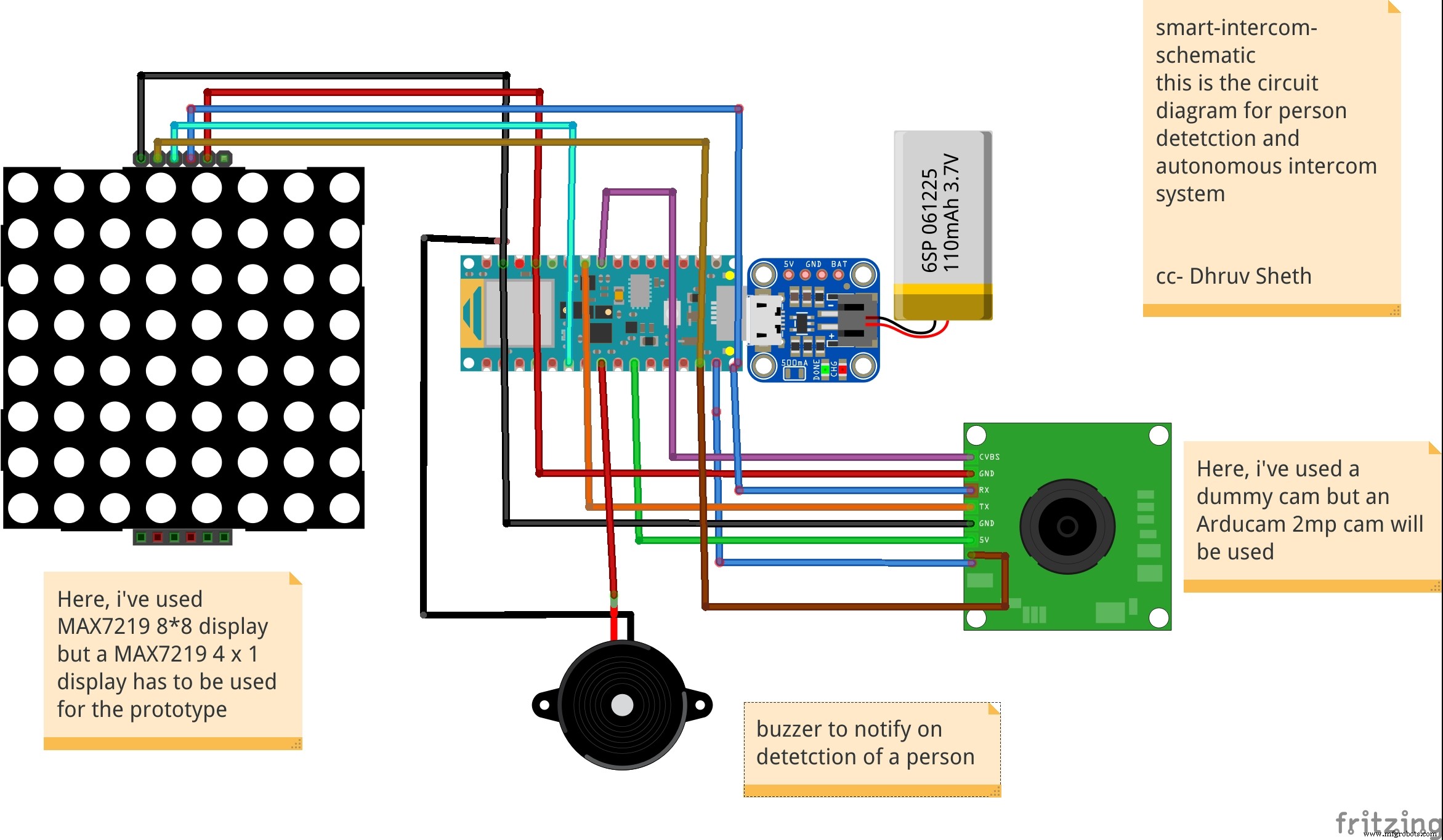
Productieproces
- Raspberry PI-gebaseerd IoT-project dat DHT11-sensor verbindt
- Draadloze protocollen voor op IoT gebaseerde oplossingen voor het volgen van bedrijfsmiddelen
- Arduino Pong Game - OLED-scherm
- Hartslagmeter met IoT
- Pixie:een op Arduino gebaseerd NeoPixel-polshorloge
- Spelen met Nextion Display
- De gezondheid van planten bepalen met TinyML
- Arduino Apple Watch
- Arduino en OLED-gebaseerde mobiele automaten
- Azure IoT-zwembad
- Op IoT gebaseerde oplossingen voor open wagons